What current does the motor consume from the network during startup and operation?
The passport of the electric motor indicates the current at the rated load on the shaft.
If, for example, 13.8/8 A is indicated, then this means that when the engine is connected to a 220 V network and at a rated load, the current consumed from the network will be equal to 13.8 A. When connected to a 380 V network, there will be a current of 8 A is consumed, that is, the power equality is valid: √ 3 x 380 x 8 = √ 3 x 220 x 13.8. Knowing the rated power of the motor (from the passport), you can determine its rated current. When the motor is connected to a three-phase 380 V network, the rated current can be calculated using the following formula:
I n = P n/ ( √3 U n x η x s osφ),
where P n is the rated power of the engine in kW, U n is the network voltage, in kV (0.38 kV). Efficiency factor (η) and power factor (with osφ) are the motor’s nameplate values, which are written on the shield in the form of a metal plate. See also - What passport data are indicated on the shield of an asynchronous motor.
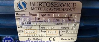
Rice. 1. Electric motor passport. Rated power 1.5 kV, rated current at voltage 380 V – 3.4 A.
If the efficiency is not known. and the power factor of the engine, for example, if there is no passport plate on the engine, then its rated current with a small error can be determined by the ratio “two amperes per kilowatt”, i.e. If the rated power of the motor is 10 kW, then the current consumed by it will be approximately 20 A.
For the motor shown in the figure, this ratio also holds (3.4 A ≈ 2 x 1.5). More accurate current values when using this ratio are obtained with motor powers of 3 kW and above.
When the electric motor is idling, a small current is consumed from the network (no-load current). As the load increases, the current consumption also increases. As the current increases, the heating of the windings increases. Large overload leads to the fact that the increased current causes overheating of the motor windings, and there is a danger of charring of the insulation (burning out of the electric motor).
At the moment of starting from the network, the electric motor consumes the so-called starting current, which can be 3 to 8 times more than the rated current. The nature of the current change is presented on the graph (Fig. 2, a).
Rice. 2. The nature of the change in the current consumed by the motor from the network (a), and the effect of high current on voltage fluctuations in the network (b)
The exact value of the starting current for each specific engine can be determined by knowing the value of the starting current multiplicity - I start / I nom. The starting current multiplicity is one of the technical characteristics of the motor, which can be found in catalogs. The starting current is determined by the following formula: I start = I n x (I start / I nom). For example, with a rated motor current of 20 A and a starting current multiple of 6, the starting current is 20 x 6 = 120 A.
Knowing the actual value of the starting current is necessary for selecting fuses, checking the operation of electromagnetic releases during engine starting when selecting circuit breakers, and for determining the amount of voltage reduction in the network during startup.
The process of selecting fuses is discussed in detail in this article: Selecting fuses to protect asynchronous electric motors
A large starting current, for which the network is usually not designed, causes significant voltage drops in the network (Fig. 2, b).
If we take the resistance of the wires going from the source to the engine equal to 0.5 Ohm, the rated current I n = 15 A, and the starting current equal to five times the rated current, then the voltage loss in the wires at the time of starting will be 0.5 x 75 + 0, 5 x 75 = 75 V.
At the motor terminals, as well as at the terminals of nearby operating electric motors, there will be 220 - 75 = 145 V. Such a decrease in voltage can cause braking of operating motors, which will lead to an even greater increase in the current in the network and blown fuses.
In electric lamps, when the engines start, the heat decreases (the lamps “blink”). Therefore, when starting electric motors, they strive to reduce the starting currents.
To reduce the starting current, a motor starting circuit can be used with switching the stator windings from star to delta. In this case, the phase voltage will decrease by √ 3 times and the inrush current will be limited accordingly. After the rotor reaches a certain speed, the stator windings switch to a delta circuit and the voltage on them becomes equal to the rated one. Switching is usually done automatically using a time or current relay.
Rice. 3. Scheme for starting an electric motor with switching the stator windings from star to triangle
It is important to understand that not every engine can be connected according to this scheme. The most common asynchronous motors with an operating voltage of 380/200 V, including the motor shown in Figure 1, will fail when switched on according to this circuit. Read more about this here: Selecting a motor phase connection diagram
Currently, to reduce the starting current of electric motors, special microprocessor-based soft start devices (soft starters) are actively used. For more information about the purpose of this type of device, read the article Why a soft start of an asynchronous motor is needed.
Source: electricalschool.info
Download
I hope readers will forgive me for my free explanation of the processes - I tried to explain everything “on the fingers”. Who needs academic knowledge, please:
• V.L. Likhachev. Asynchronous electric motors. 2002 / The book is a reference book that describes in detail the design, operating principle and characteristics of asynchronous electric motors. Reference data is provided for engines of previous years of production and modern ones. Electronic starting devices (inverters), electric drives are described., djvu, 3.73 MB, downloaded: 7198 times./
• Bespalov, Kotelenets - Electrical machines / Transformers and electrical machines used in modern technology are considered. Their decisive role in the generation, distribution, conversion and utilization of electrical energy is shown. The basic theory, characteristics, operating modes, examples of designs and applications of electrical generators, transformers and motors are given., pdf, 16.82 MB, downloaded: 2345 times./
• MM. Katzman - Electrical Machines / Some say this is the best textbook on electrical engineering. The book discusses the theory, principle of operation, design and analysis of operating modes of electrical machines and transformers, both general and special purpose, which have become widespread in various branches of technology., pdf, 22.12 MB, downloaded: 2108 times./
• Electromash motor catalog / Asynchronous electric motors with squirrel-cage rotor - manufacturer’s catalog, pdf, 3.13 MB, downloaded: 1401 times./
• VEMZ engines catalog / Engine parameters and catalogue, pdf, 3.53 MB, downloaded: 1197 times./
• Dyakov V.I. Typical calculations for electrical equipment / Practical calculations for electrical equipment, theoretical information, calculation methods, examples and reference data., zip, 1.53 MB, downloaded: 2554 times./
• Karpov F.F. How to check the possibility of connecting several motors to the electrical network / The brochure shows the calculation of the electrical network for voltage fluctuations during the start-up and self-starting of asynchronous motors with squirrel-cage rotor and synchronous motors with asynchronous starting. The conditions under which starting and self-starting of engines are permissible are considered. The presentation of calculation methods is illustrated with numerical examples. The brochure is intended for qualified electricians as a guide when choosing the type of electric motors connected to a municipal or industrial power supply network., zip, 1.9 MB, downloaded: 1665 times./
• Operating manual for asynchronous motors / This manual contains the most important instructions for transportation, acceptance, storage, installation, commissioning, operation, maintenance, troubleshooting and troubleshooting for electric motors produced by Elektromashina. The operating manual is intended for three-phase asynchronous electric motors of low and high voltage series A, AIR, MTN, MTKN, 4MTM, 4MTKM, DA304, A4., pdf, 7.54 MB, downloaded: 2566 times./
• Catalog of AIR engines / Catalog of AIR engines - power from 0.12 to 315 kW; rotation speed 3000, 1500, 1000, 750 rpm; mains voltage 220/380 V, 380/660 V;, pdf, 1.07 MB, downloaded: 1076 times./
• Lomonosov, V.Yu.; Polivanov, K.M.; Mikhailov, O.P. Electrical engineering. / Lomonosov, V.Yu.; Polivanov, K.M.; Mikhailov, O.P. Electrical engineering. One of the best books on the basics of electrical engineering. The presentation begins with the very basics: it explains what voltage, current and resistance are, provides instructions for calculating the simplest electrical circuits, and talks about the relationship and interdependence of electrical and magnetic phenomena. Explains what alternating current is and how an alternating current generator works. It describes what a capacitor is and what an inductor is, what their role is in alternating current circuits. It is explained what three-phase current is, how three-phase current generators are designed and how its transmission is organized. A separate chapter is devoted to semiconductor devices: it talks about semiconductor diodes, transistors and thyristors; on the use of semiconductor devices for rectifying alternating current and as semiconductor switches. The achievements of microelectronics are briefly described. The last third of the book is entirely devoted to electrical machines, units and equipment: chapter 10 deals with direct current machines (generators and motors); Chapter 11 is devoted to transformers; AC machines (single-phase and three-phase, synchronous and asynchronous) are described in detail in Chapter 12; switches, electromagnets and relays are described in Chapter 13; Chapter 14 deals with electrical diagramming. The last, chapter 15, is devoted to measurements in electrical engineering. This book is an excellent way to learn the basics of electrical engineering, to understand the fundamental principles of the operation of electrical machines and units., zip, 13.87 MB, downloaded: 2730 times./
Another manual on motors: • Starting and protecting AC motors / Starting and protecting AC motors. Starting and braking systems for AC motors. Protection devices and fault analysis of AC motors. Guide to selecting protection devices. Manual from Schneider Electric, pdf, 1.17 MB, downloaded: 2108 times./
How to determine the power and current of an electric motor
All electric motors are produced with plates on the housing, from which you can find out the main characteristics of the electric motor: its brand, rated operating current and power consumption, rotation speed, motor type, efficiency and cos(fi). This data is also indicated in the passport for the device.
Of all the parameters, the most important for connection are: the power of the electric motor and the current consumption; this should not be confused with the starting one. It is these data that allow us to determine the sufficiency of power for the drive, the required cable cross-section for connecting the motor, and select the appropriate circuit breaker and thermal relay for protection.
How to determine the power of an electric motor
The easiest way is to look at the plate and find the value in kilowatts. For example, in the picture it is 45 kW.
Please note that this value on the plate indicates the active power consumed from the electrical network. The total power will be equal to the sum of active and reactive power. Electric meters in a house or garage count only the consumption of active electricity, and reactive energy is recorded only in enterprises using special meters. The higher the cos(fi) of an electric motor, the lower the reactive energy component of total power will be. Do not confuse cos(fi) with efficiency. This indicator shows how much electricity is converted into useful mechanical work, and how much into useless heat. For example, an efficiency of 90 percent means that a tenth of the electricity consumed is spent on heat losses and friction in the bearings.
You should keep in mind that the passport or plate indicates the rated power, which will be equal to this value only if the optimal load on the shaft is achieved. However, you should not overload the shaft for a number of reasons; it is better to choose a more powerful motor. At idle, the current will be much lower than the nominal value.
How to determine the rated power of an electric motor? On the Internet you will find many different formulas and calculations. For some, you need to measure the dimensions of the stator, for other formulas you will need to know the current value, efficiency and cos(fi). My advice is don't bother with all this. Practical measurements will still be better than these calculations. And you won’t need anything at all to carry them out.
How to determine the power of any electrical appliance in the house or garage? Of course, using an electricity meter. Before starting the measurement, unplug all electrical appliances from the sockets, lighting and everything connected to the electrical panel.
Next, if you have an electronic meter of the Mercury type, everything is very simple: you just need to turn on the motor under load and drive for about 5 minutes. The electronic display should display the load value in kW currently connected to the meter.
If you have a disk induction meter, keep in mind that it keeps records in kilowatt/hours. Write down the latest readings before starting measurements, turn on the engine strictly second per second for exactly 10 minutes, then after stopping, subtract the new readings from the previous ones and multiply kWh by 6. The result obtained will be the active power of this engine in Kilowatts; to convert to Watts, divide by 1000 I recommend reading the article: how to take electric meter readings.
If the engine is low-power , then for higher accuracy you can count the disk revolutions. For example, in one minute it made 10 full revolutions, and the meter says 1200 revolutions = 1 kW/h. We multiply 10 by the number of minutes in an hour and get 600 revolutions per hour. Divide 1200 by 600 and we get 500 watts or 0.5 kW. The longer you measure, the more accurate the data will be. But the time must always be a multiple of a full minute. Then divide 60 by the number of minutes of measurement and multiply by the counted revolutions. After this, we divide the value of revolutions equal to one Kilowatt/hour for your electric meter model by the result obtained and obtain the required amount of power.
How to determine the current consumption of an electric motor
Knowing the power , you can easily calculate the amount of current consumed. For 3-phase motors connected in a 380-volt star configuration, it is necessary to multiply the power in kilowatts by 2. For example, with a power of 5 kilowatts, the current will be 10 Amperes. Again, keep in mind that the motor will take such current only under a load as close as possible to the nominal value. A semi-loaded electric motor, and even more so at idle, will consume significantly less current.
To determine the current in single-phase networks, it is necessary to divide the power by voltage. For example, when the engine is running, the voltage at its connection point is 230 Volts. This is important because after turning on the load, the voltage will most likely drop at the point where the electric motor is connected.
If, for example, the power of a 220 Volt motor was measured to be 1.5 kW or 1500 Watts. Divide 1500 by 230 Volts and we find that the operating current of the motor is approximately 6.5 Amperes.
Motor starting current
When starting any type of electric motor, a starting current occurs from 2 to 8 times the rated current in the operating mode of the electric motor. The magnitude of the starting current depends on the type of motor, rotation speed, connection diagram, presence of load on the shaft and other parameters.
The starting current occurs because at the moment of starting a very strong magnetic field is induced in the windings, which is necessary to move and spin the rotor. When the motor is turned on, the resistance of the windings is low, and therefore, according to Ohm’s law, the current increases at a constant voltage in the circuit section. As the motor spins up, an emf or inductive reactance appears in the windings and the current begins to decrease to the rated value.
These surges of reactive energy negatively affect the operation of other electrical consumers connected to the same power line, which causes voltage surges or surges that are especially destructive for electronics.
What happens if you install a battery with a high starting current?
Some car owners and highly qualified “experts” believe that a battery with a large capacity and an appropriate starting current can cause failure of the on-board electrical network. This opinion mainly exists among illiterate vehicle owners.
Important! Even if you install a good battery on a passenger car from a large truck, for example, from a KrAZ, then when starting, the starter will consume only the electric current that it needs to turn the engine crankshaft, and no more.
The main reason why high-capacity batteries are not installed on cars is the lack of free space in the engine compartment. Manufacturers of various car brands are hesitant to increase the standard locations for batteries, as this will directly affect the size of the body. An increase in dimensions will entail greater weight of the machine, which will have a bad effect on its throughput characteristics.
High-capacity batteries are often used when the standard battery is completely discharged. For example, at service stations or service centers. The 180 ampere/hour battery is convenient to carry; it can be placed on the floor, and the terminals can be connected with special wires with “crocodile clips” to the car’s starting system.
Starting currents of asynchronous electric motors
Asynchronous motors, when connected to the mains, consume a significant amount of energy in order to:
- set the rotor in motion;
- increase the rotation speed from zero to the operating level.
This explains the need to use a large starting current, which differs significantly from the amount of electricity that allows maintaining a constant speed. This is typical not only for asynchronous, but also for single-phase DC motors, although the operating principle of the latter is completely different.
High inrush current problem: solution
High inrush current can cause a sudden, albeit short-term voltage drop, causing other devices connected to the network to experience a lack of power. This is undesirable because it negatively affects the safety of operation and the durability of the equipment.
To solve the problem, special additional devices are provided, the installation of which during the process of connecting and adjusting the engines allows:
- reduce the starting current as much as possible;
- improve startup smoothness;
- reduce the cost of starting the unit, since it becomes possible to use less powerful diesel power plants, stabilizers, wires with a smaller cross-section, etc.
The most effective are modern devices such as frequency converters and soft starters. They provide a high (more than a minute) duration of maintaining the inrush current.
Connecting an asynchronous motor
The stator winding of almost any such device has six terminals (of which three are the beginning and three are the ends). Depending on the power supply network of the motor, these terminals are connected either in a “star” or in a “triangle”. For this purpose, the housing of each motor has a box in which the starting and ending wires of the windings are located (they are designated, respectively, C1, C2, C3 and C4, C5, C6).
Star connection
This is the name for the method of connecting windings in which all three windings have one common point (neutral). The linear voltage of such a connection is 1.73 times higher than the phase voltage. Low starting currents are considered a positive quality of this type of connection, although the power losses are quite significant.
The delta connection method differs in that with this method the connection is made in such a way that the end of one winding becomes the beginning of the next.
Delta connection
In this case, the connection phase and linear voltages are the same, therefore, with a linear voltage of 220 volts, the correct connection of the windings will be a triangle. The positive side of this connection is high power, while the negative side is high starting currents.
To reverse (change the direction of rotation) of a three-phase asynchronous motor, it is enough to swap the leads of its two phases. In production, this is done using a pair of magnetic starters with dependent switching.
Significant starting currents for asynchronous motors are a very undesirable phenomenon, because they can lead to a voltage shortage effect for other types of equipment connected to the same network. This was the reason that when connecting and setting up motors of this type, the task arises of minimizing starting currents and increasing the smoothness of starting motors by using specialized equipment. The most effective types of such devices are soft starters and frequency converters. One of their most valuable qualities is that they are able to maintain the motor starting current for quite a long time (usually more than a minute).
In addition to the standard method of turning on asynchronous motors, there are also methods for connecting them to a supply network that has only one phase.
Capacitor starting of an asynchronous motor
For this purpose, the capacitor switching method is mainly used. The capacitor can be installed either alone or in pairs (one starting and the second working). A pair of condensers is installed when there is a need to change the capacity during start-up and operation, which is done by connecting and disconnecting one of the condensers (starting). For this, as a rule, paper containers are used, since they do not have polarity, and when operating on alternating current, this is very important.
To calculate the working capacitor there is the following formula:
The starting capacitor must have a capacity two to three times greater than the operating capacitor and an operating voltage one and a half times higher than the supply voltage.
The starting and running capacitors are connected in parallel, so that in parallel with the starting capacitor, a shunt resistor is switched on and one end of the starting capacitor is switched on through a switch. When starting the engine, the key is closed, increasing the starting current, then it is opened.
However, we must not forget that not every engine can be connected to a single-phase network. In addition, the power of the motor in such a connection will be only 0.5-0.6 of the power of a three-phase connection.
How to calculate the starting current of an electric motor
In order to objectively assess the complexity of the engine starting conditions, it is necessary to first know the amount of starting current required for this. The main calculation steps are as follows:
- calculation of rated current;
- determination of the starting current value (in amperes).
In order to obtain the value of the rated current for the used electric motor model, use a formula that has the form Iн=1000Pн / (Un*cosφ*√ηн). Pн and Un are the rated power and voltage indicators, cosφ and ηн are the rated power and efficiency factors.
The actual starting current, which is designated as Iп, is determined using the formula Iп = Iн * Kп, where Kп is the multiple of the direct current in relation to its rated value (Iн). All information necessary for calculations (values of Kp, Pn, ηn, cosφ, Un) can be found in the technical documentation that comes with the electric motor.
Correct calculation of the motor starting current facilitates the correct selection of circuit breakers designed to protect the switching line, as well as the purchase of additional equipment (generators, etc.) with suitable parameters.
Source: www.szemo.ru
Verification methods
The test procedure is designed to reproduce the conditions during winter starting of the car. This is not the easiest way to estimate inrush current. But it is considered the most reliable.
The standards are defined as follows:
- The battery is placed in a refrigerator and the temperature is reduced to -18°C.
- After this, a discharge current is sent to the device, which is equal to the rated starting current. Let's say the device has a starting current of 300A, which means the discharge current should also be 300A.
- For a device to pass the test, its voltage must not drop below the specified standard.
But first, we need to say a few words about world standards, which directly affect the final result. But the thing is that in different countries the starting current has its own standards.
- European Union (Europa Norm) - after discharge current for 10 seconds. the charge should not fall below 7.5A.
- Germany (DIN) – battery after 50 sec. should not discharge below 9V.
- USA (SAE) - after the discharge current was sent to the device, after 50 seconds. the voltage should not fall below 7.2V.
Important! Russian GOST has exactly the same standards as in Germany.
There are also so-called launch testers. They induce a powerful pulse that corresponds to the rated inrush current. Using Ohm's law, the device calculates the battery resistance, and then reads the starting current data. This way you can check your data much faster. But the result may not be entirely accurate.
Starting currents of electrical equipment
Electricity users are not left indifferent by the power of electrical appliances that surround us in everyday life, because in the end it comes down to the capabilities of our wallet. We take into account the total power from the figures indicated in the documentation for electrical appliances when designing a future network, however, we do not always take into account that the manufacturer indicates the electrical characteristics for equipment operating in nominal mode.
In real conditions, most electrical appliances exceed their rated power, reaching their maximum load the moment they are turned on. This happens due to inrush currents, which for a short period of time (from tenths to several seconds) exceed the rated current consumption by up to 10 times.
These features are typical for electrical appliances that have electric motors (refrigerators, air conditioners, electric pumps), and electric heating devices using heating elements. Oddly enough, even ordinary incandescent lamps have fairly high inrush current values from 5 to 13 times higher than the rated values (it’s not for nothing that they almost always burn out the moment they are turned on).
Nature of inrush currents
It is easy to illustrate the reason for the occurrence of inrush current using a simple example. Anyone who has ever ridden a bicycle knows that the first turns of the pedals require the most effort, when the bicycle starts moving; then, when the rated speed is reached, it is much easier to do this.
Similar processes occur when starting an electric motor, because to overcome the inertia of the motor shaft and associated mechanisms, a powerful electromagnetic field is required, which operates until the operating speed is reached. It is characterized by higher currents when starting the engine, related to the rated values using starting current coefficients (multiple of the starting current to the rated value).
The nature of inrush currents is different for incandescent lamps. The resistance value of the tungsten filament of a 100-watt light bulb in a cold (off) state is 40 Ohms, and in a hot (on) state it is 490 Ohms. It is not surprising that the current at the moment of switching on is more than 12 times higher than the rated current of the lamp. The resistance of the nichrome filament of the heating element of an electric heating device changes in a similar way.
Voltage measurement
If you cannot measure the current value of the car battery with your device because the ammeter is broken or missing, you can perform diagnostics in a slightly different way - by monitoring the voltage. Connect a voltmeter to the battery terminals, the display will show the actual drop reading at the source. But this doesn't tell us anything about the current, because we don't know the resistance.
To measure current, you need to switch the tester to voltage measurement mode and connect the load to the battery, having first measured its resistance in Ohms. As a load, you can use a powerful incandescent high beam lamp 60-100 W. If the battery charge is normal, the voltage value will not change. In this case, the current can be determined by the formula:
I = U / R, where U is the voltage across the light bulb, R is its resistance.
You can also display this value through power:
I = P / U, where P is the lamp power.
If you want to determine exactly the starting current, it is better to use your starter. This way you will comprehensively study the car’s battery capabilities, charge and capacity. To do this you need to do the following:
- Switch the tester to voltage measurement mode.
- Without removing anything, connect the probes to the battery terminals.
- Turn off the generator, remove the wire that powers the service winding or ground.
- Start the engine in normal mode with the starter.
Take car battery current measurements within a few seconds because a worn-out battery will drain quickly. If the voltage on the device does not drop below 9 V, then your battery is still in perfect order. By European standards it passes quite well. If the power supply falls below 9 V according to DIN standards, it is time to replace it. Accordingly, if the voltage drops below 7.5 V according to EN, the battery is also faulty.
This method allows you to give an objective assessment of the battery condition. Such a check, of course, does not give the complete picture, but you will understand that the current source is still capable of working. There are tables by which you can check the condition of your battery if it is on the list of tested ones. They present the big picture.
On the left in the column we see the initial data:
- capacity;
- cold start;
- deep discharge;
Based on the results of all tests, each car battery gains a certain number of points. The table shows that a greater number of charge/discharge cycles belong to AGM batteries with sorbent. As you can see, the test was carried out under different conditions.
Electric motor power calculation
Electric motor power by current can be calculated using our online calculator:
The result can be rounded to the nearest standard power value.
Standard values of electric motor power : 0.25; 0.37; 0.55; 0.75; 1.1; 1.5; 2.2; 3.0; 4.0; 5.5; 7.5; eleven; 15; 18.5; 22; thirty; 37; 45; 55; 75 kW, etc.
Engine power is calculated using the following formula:
P=√3UIcosφη
- U - Rated voltage (voltage to which the electric motor is connected);
- I - Rated current of the electric motor (taken from the passport data of the electric motor , and in their absence is determined by calculation);
- cosφ - Power factor - the ratio of active power to total power (taken from 0.75 to 0.9 depending on the power of the electric motor);
- η - Efficiency factor - the ratio of the electrical power consumed by the electric motor from the network to the mechanical power on the motor shaft (taken from 0.7 to 0.85 depending on the power of the electric motor);
Motor current calculation
The rated and starting current of an electric motor can be calculated by power using our online calculator:
The rated motor current is calculated using the following formula:
Inom=P/√3Ucosφη
- P - Rated power of the electric motor (taken from the motor’s passport data or determined by calculation);
- U - Rated voltage (voltage to which the electric motor is connected);
- cosφ - Power factor - the ratio of active power to total power (taken from 0.75 to 0.9 depending on the power of the electric motor);
- η - Efficiency factor - the ratio of the electrical power consumed by the electric motor from the network to the mechanical power on the motor shaft (taken from 0.7 to 0.85 depending on the power of the electric motor);
The starting current of the electric motor is calculated using the formula:
Istart=Inom* K
- K - Starting current multiplicity, this value is taken from the electric motor passport, or from catalog data (in the above online calculator, the starting current multiplicity is determined approximately based on the other specified characteristics of the electric motor).
Subtransient current and protection setting
- The peak value of subtransient current can be extremely high. Typically this value is 12-15 times the rms nominal value Inm. Sometimes this value can be 25 times the Inm value.
- Circuit breakers, contactors and thermal relays are designed to start motors at extremely high subtransient currents (subtransient peak value can be up to 19 times the rms rated value Inm).
- If the overcurrent protection suddenly trips during startup, this means that the starting current goes beyond normal limits. As a result, switchgear parameters may be reached to their limits, service life may be shortened and even some devices may fail. To avoid such a situation, it is necessary to consider increasing the rated parameters of switchgears.
- Switchgears are designed to protect motor starters from short circuits. Depending on the risk, the tables show combinations of circuit breaker, contactor and thermal relay to provide type 1 or 2 coordination.
Calculation of electric motor power factor
Online calculation of power factor (cosφ) of an electric motor
Calculation of cosφ (cosine phi) of the engine is carried out using the following formula:
cosφ=P/√3UIη
- P - Rated power of the electric motor (taken from the motor’s passport data or determined by calculation);
- U - Rated voltage (voltage to which the electric motor is connected);
- I - Rated current of the electric motor (taken from the passport data of the electric motor , and in their absence is determined by calculation);
- η - Efficiency factor - the ratio of the electrical power consumed by the electric motor from the network to the mechanical power on the motor shaft (taken from 0.7 to 0.85 depending on the power of the electric motor);