Installation of electrical wiring in a building (residential or industrial) is carried out in two ways - hidden or open; the electrical wiring itself can be permanent or replaceable. Hidden installation of electrical wiring and its fastening in concrete is considered the most difficult option due to the strength of the building material and the restrictive conditions for laying grooves in panel houses. But even under favorable installation conditions, it will not be possible to install a hidden line in every building. Thus, a wooden house is not intended for such installation, and it is not allowed to lay grooves in a single facing brick, so as not to damage the decorative surfaces of the product - wiring under plaster must be implemented without grooves.
Rules for installing hidden electrical wiring
According to the rules for electrical installations (PUE) and building codes (SNiP), in internal residential premises, power supply lines for household equipment, appliances and devices are laid with copper cable in non-flammable or fire-resistant insulation. Aluminum does not withstand heavy loads, although previously only aluminum internal lines were used.
PUE and SNiP allow the laying of electrical cables of the following sections:
- Supply cable to the switchboard - brand VVG-2, cross-section 6 mm2 or brand VVG-5, cross-section 6 mm2;
- Laying wires around the apartment and connecting electrical sockets - brand VVG-3, cross-section 2.5 mm2;
- The supply to electrical switches and lighting devices is VVG-3 brand, cross-section 1.5 mm2.
Also, when laying an internal electrical network, the best option for connecting electrical outlets is a VVG cable with a cross-section of 2.5 mm2, and for laying lighting networks - a PUGNP wire with a cross-section of 1.5 mm2. For rooms with high humidity, it is recommended to mount PVA grade wire.
The question of when to do wiring before or after plastering is easily resolved - if gating is necessary, then first lay the electrical lines, after which the plaster layer is applied.
Let's start installing the wiring yourself
Armed with knowledge, material and tools, let’s get to work:
- Mark with a pencil on the wall the space allocated for the junction box. It is very convenient to use a building level when marking;
- From the distribution box we draw straight lines to the points where the switches and sockets are located. We draw the lines vertically. Where the wire makes turns, we make a rounding. The cable specification indicates the radius. Usually it is equal to 6 conductor diameters.
More details about all the operations to be performed:
Grilling
We arm ourselves with a wall chaser and begin:
- the work is dusty, so if there is furniture in the room, it is better to take it out or cover it with something;
- We protect our face with a mask and our ears with earplugs;
- According to the markings made, we make two grooves with a depth equal to the diameter of the wire plus 1 cm. The distance between the grooves is about 40 mm;
- There is space between the grooves and we eliminate it using a chisel and hammer.
If there is no wall chaser and you use a hammer drill, then:
- along the marked line we make a chain of holes spaced 5-10 mm from each other;
- Now we take a chisel, a hammer, remove the jumpers between the holes, i.e. we make a groove.
Recesses for sockets and switches
All electrical points also require recesses. Let's do them:
- we drill a series of holes in the place where there will be either an outlet, or a switch, or a box. The depth of the holes is such that if you insert a socket, it should sink;
- We connect all the holes by picking up a chisel and a hammer.
Installing the cable
- When all the deepenings have been completed, we break out the hatches of the socket boxes, then insert the wires into the previously prepared seats and secure them using plaster.
- We lay the cable in the grooves, securing it with dowel clamps. For this:
- measure out the required segments;
- at the points where we will fasten, we drill holes with a hammer drill using a 6 mm drill, 6 cm long;
- We wrap the piece of conductor with a dowel clamp and insert it into the holes. For example: for a 3-core cable going to lighting fixtures or sockets, the cross-section is 1.5 and 2.5 square meters, respectively. mm, you will need UW fasteners, which are marked 5/10. There are other types of mounts, but UW is the most convenient;
- cover the cable with plaster, having previously removed dust from the recess with a brush;
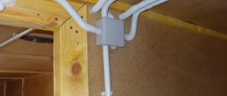
- finally you can install the distribution box.
Installation of distribution box
Installation of a distribution box is a responsible matter:
- First we choose a place. Usually it is located higher under the ceiling;
- carry out deepening;
- insert the junction box into this seat;
- For fastening we use cement mortar or alabaster.
Attention: when it comes time to connect the wires in the box, mark the end of each of them. For example: “to the electrical panel”, “to the sockets”, “to the switches”
It is important that each chain is labeled separately. By following this advice, you will save yourself from questions about where and which wire to connect
Final point: connecting the wires
This process will go smoothly if you understand how the wiring works. So:
- we have wires and an input where they need to be connected;
- the input consists of 2 or 3 wires of different colors. There is a phase, “zero”, grounding;
- This is how we connect them: phase to phase, zero to zero, ground to ground;
- When we connect sockets, we simply connect wires of the same color.
Lighting is connected a little differently:
- we connect the outgoing phase to the phase of the lighting circuit;
- the incoming zero must be aligned with the illumination zero.
The quality of the connection is very important:
- it is 100% guaranteed if the box is a communication one, because it has terminals that securely clamp the wires;
- In the absence of special terminals, soldering of wires is used.
It is done like this:
- twist the wires together using pliers;
- We perform soldering using special solder. If electrical wiring is installed over a large area, then instead of soldering it is more advisable to use electric welding;
- After all the manipulations have been done, close the distribution box.
Advice: provide yourself with free access to the junction box - it will be easier to carry out repair work.
Requirements for the number of wire cores
Electrical installation in residential buildings and premises is carried out with a copper cable of three cores. One wire is phase, the second wire is zero, the third wire is grounding.
2 options for grounding wiring have been developed, and they differ from each other in the point of separation of the neutral wire:
- TN-S - separation of the working neutral wire (N);
- TN-CS - separation of the protective neutral conductor (PE).
The grounding wire is designed to protect against electric shock and protect household appliances from failure. When laying wiring, the grounding must have reliable terminal connections. Correct installation of electrical wiring requires that twisting wires together and using bolted connections is strictly prohibited by the PUE and SNiP. In addition to terminals, soldered wiring connections are permitted. A typical installation of electrical wiring in a brick house requires that soldered or terminal connections are hidden in distribution boxes, in glasses for mounting sockets, or in distribution boards with free access.
It is recommended to replace old aluminum wires with copper wiring. If it is not possible to replace aluminum with copper, connecting wiring from different materials is allowed only at terminals.
If you don’t know how to connect wires under plaster, then there is only one answer - waterproof terminals.
Plan-scheme of laying highways
Safe installation of electrical wiring is unthinkable without clear preliminary planning with the design of a working diagram.
A home craftsman can create a plan on paper using a pencil and an ordinary ruler or tape measure, which makes it easier to accurately measure distances. But for its reliable operation, knowledge of the electrical circuit and the skills of an experienced electrician are required.
If they are not enough, then you can turn to specialists for help, using the “Electrician 7.8” computer program to perform technical calculations. It is specially designed to facilitate such work, is supplied free of charge, and performs complex circuit calculations using well-thought-out algorithms and input data.
You can visually draw up a diagram of the lighting circuits as well as the mains of the power socket group in the Visio office program. These issues have already been covered in separate articles.
Installation of hidden electrical wiring: rules and sequence
Wiring is laid in a brick house in stages, and the first step is to develop a layout of the premises and select a connection option. Drawings or sketches of the plan must include a detailed description of the work to be done. For each room, a separate drawing is drawn up with a layout of the walls and a wiring diagram.
Important rules for laying wires:
- A distance of ≥ 150 mm is maintained from the wiring to the floor or ceiling surface, from a window or door ≥ 100 mm, from the heating system pipes ≥ 30 mm;
- Electrical wires are laid strictly vertically or horizontally - tilting at any other angle is strictly prohibited;
- Wiring in a brick house, and even more so in a wooden building, should not intersect; lines overlapping each other is unacceptable.
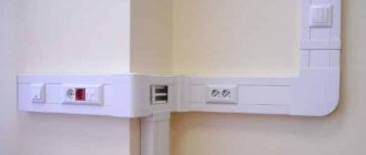
What can you do to hide wires from your computer?
You can also secure and hide the wires from the computer under the table and in the area of the work surface using ordinary cable ducts and plastic cable ties that electricians use. You can also look for something practical on Aliexpress. The code name is “cable clamp”. Well, there are many other Chinese variations.
The price ranges from 50-200 rubles. per set with different number of pieces. Here you need to be careful when choosing what quantity and for how much the seller offers. And most importantly - how much delivery costs. Not everyone makes it free; some are cunning and thus cover a low, attractive price.
With baskets, the choice is smaller and not as favorable in terms of price, but something can be adapted from organizers for closets and kitchens.
Main characteristics of wires
Reliable fastening of the wire to the wall under plaster depends on the properties of the cable or wire. Electric wire under plaster brand and some other distinctive characteristics:
- Section in mm2 –0.75-8.00;
- Material - Cu, Al and their alloys;
- According to the number of cores, wiring under plaster can consist of 1-37 single wires;
- The wiring on the shell before or after plastering can be plastic, rubber or even steel;
- According to the type of insulation, electrical insulation before or after plastering is made from cellulose, plastic, silicone, polymers, rubber.
What is the difference between a cable under plaster and wiring - wires have outer insulation made of thinner and softer material. The retail cost of wire for plaster will be lower than the price for cable. But the cable lasts longer, and this is its main advantage.
The decoding of the brand of wire or cable contains their properties, parameters and quality indicators. The first Cyrillic character means the core material. For example, “A” is a wire or cable made of aluminum (Al). Copper (Cu) wires are not marked. The remaining symbols in the cable or wire brand indicate the parameters and properties of other elements.
High-quality electrical installations, before or after plastering, must consist of two protected layers of insulation. Typical cable laying in the wall of a residential building or in an apartment is carried out in the same way as installing wires.
Apartment power cable
The apartment's power cable belongs to the distribution networks of the house. It can also be installed hidden, in special channels, in grooves, in the floor of the first screed.
Note: For any hidden wiring, you can use not a cable, but wires in a protective sheath. True, I do not recommend using wires, even protected ones, for permanent (immured) electrical wiring, without pipes.
We have sorted out the general issues of hidden wiring in the apartment, let’s move on to installation.
Selection of wire cross-section
An incorrect choice of wiring cross-section can lead not only to an overload in the general network, but also to a fire in the local overload area, which often means overheating of the wiring. The tables in this section will help you correctly determine the cross-section and select the type of wiring depending on the loads and characteristics of the wires.
| Number of cores and cross-section | Class | ⌀ with insulation in mm | ⌀ with shell in mm | Ωmin (Ohm) with a wire length of 1.0 km and t = 20°C | Coil length in meters | Wire weight (kg/km) | Dmin bending in mm |
| 3 x 4 | I | 3.73 | 11.62 | 4.61 | 100.0 | 235.19 | 7,5 |
| 3 x 6 | I | 4.22 | 12.67 | 3.08 | 100.0 | 305.92 | 7,5 |
| 3 x 10 | I | 5.46 | 15.34 | 1.83 | bar | 475.30 | 7,5 |
| 3 x 16 | II | 7.02 | 18.69 | 1.15 | bar | 724.59 | 7,5 |
| 4 x 1.5 | I | 2.67 | 10.03 | 12.1 | 100.0 | 153.33 | 7,5 |
| 4 x 2.5 | I | 3.05 | 10.95 | 7.41 | 100.0 | 201.75 | 7,5 |
| 4 x 4 | I | 3.73 | 12.59 | 4.61 | 100.0 | 285.59 | 7,5 |
| 4 x 6 | I | 4.22 | 13.77 | 3.08 | 100.0 | 375.54 | 7,5 |
| 4 x 10 | I | 5.46 | 16.76 | 1.83 | bar | 588.92 | 7,5 |
| 4 x 16 | II | 7.02 | 20.52 | 1.15 | bar | 902.80 | 7,5 |
| 5 x 1.5 | I | 2.67 | 10.81 | 12.1 | 100.0 | 178.58 | 7,5 |
| 5 x 2.5 | I | 3.05 | 11.84 | 7.41 | 100.0 | 237.36 | 7,5 |
| 5 x 4 | I | 3.73 | 13.67 | 4.61 | 100.0 | 338.80 | 7,5 |
| 5 x 6 | I | 4.22 | 14.99 | 3.08 | 100.0 | 448.59 | 7,5 |
| 5 x 10 | I | 5.46 | 18.34 | 1.83 | bar | 707.92 | 7,5 |
| 4 x 16 | II | 7.02 | 22.55 | 1.15 | bar | 1089.41 | 7,5 |
Using the data in the table, you can quickly calculate the wiring cross-section in mm2, based on the maximum load current values:
| Open laying scheme | Section in mm | Closed routing scheme | ||||||||||
| Cu | Al | Cu | Al | |||||||||
| I (A) | P (kW) | I (A) | P (kW) | I (A) | P (kW) | I (A) | P (kW) | |||||
| 220 V | 380 V | 220 V | 380 V | 220 V | 380 V | 220 V | 380 V | |||||
| 11 | 2.4 | — | — | — | — | 0.5 | — | — | — | — | — | — |
| 15 | — | — | — | — | 0.75 | — | — | — | — | — | — | |
| 17 | 3.7 | 6.4 | — | — | — | 1.0 | 14 | 3.0 | 5.3 | — | — | — |
| 23 | 5.0 | 8.7 | — | — | — | 1.5 | 15 | z.z | 5.7 | — | — | — |
| 26 | 5.7 | 9.8 | 21 | 4.6 | 7.9 | 2.0 | 19 | 4.1 | 7.2 | 14 | 3.0 | 5.3 |
| 30 | 6.6 | 11 | 24 | 5.2 | 9.1 | 2.5 | 21 | 4.6 | 7.9 | 16 | 3.5 | 6.0 |
| 41 | 9.0 | 15 | 32 | 7.0 | 12 | 4.0 | 27 | 5.9 | 10 | 21 | 4.6 | 7.9 |
| 50 | 11 | 19 | 39 | 8.5 | 14 | 6.0 | 34 | 7.4 | 12 | 26 | 5.7 | 9.8 |
| 80 | 17 | 30 | 60 | 13 | 22 | 10 | 50 | 11 | 19 | 38 | 8.3 | 14 |
| 100 | 22 | 38 | 75 | 16 | 28 | 16 | 80 | 17 | 30 | 55 | 12 | 20 |
| 140 | 30 | 53 | 105 | 23 | 39 | 25 | 100 | 22 | 38 | 65 | 14 | 24 |
| 170 | 37 | 64 | 130 | 28 | 49 | 35 | 135 | 29 | 51 | 75 | 16 | 28 |
Preparatory procedures
After submitting an application to the regional distribution zone at your place of residence and receiving an agreement with the technical specifications, you can design the power supply. They do this in the following order:
- calculate the total power of consumers, adding a margin of 30%;
- draw a diagram of the input cable, electrical panel, as well as wiring, sockets, lighting fixtures, etc.;
- select the wire cross-section depending on the consumers;
- determine the optimal location of distribution boxes for sockets and lighting devices;
- indicate the optimal route for laying the cable.
During the design process, you should indicate at what distance the wire runs from the window, doorway, floor and ceiling.
When drawing up a project, you must adhere to the PUE. This document specifies that wiring must be installed vertically or horizontally. The optimal rotation angle is 90°. Sockets and switches should be located in areas with easy access. Most often, switches are installed at a height of 80-150 cm from the floor, and sockets - 50-80 cm. The number of sockets can be from 1 to 6 pieces, which is determined by the size of the room and the number of consumers.
When designing the wiring, you need to take into account that the wire from the openings should be located no closer than 10 cm. If contact with metal elements may occur along the wiring path, make a cable outlet of 30 cm in a convenient direction.
Selecting cables and devices
To lay electricity in a private home, the following types of cables are most often used:
- NYM;
- VVGng.
The first option meets European standards and is used for electrical wiring with a rated voltage of up to 660 V. The second wire is a bare power cable with two layers of vinyl braiding, designed to operate in networks with voltages up to 1 kV.
One of the main characteristics of the cable is the cross-section, indicated in mm². The marking consists of two numbers. The first indicates the number of wires inside the insulation, and the second indicates the cross-section of the wire. The easiest way to determine the required section is by referring to the table:
It is worth considering that for hidden wiring, the cable cross-section should be 30% larger than for open wiring.
For wiring in wooden houses, it is recommended to use only copper wires, which reduces the likelihood of network overheating.
In accordance with the PUE, RCDs and electrical circuit breakers must be installed at each section of the electrical network, which must be designed for the appropriate load. The current can be calculated using the formula I=P/U•cos, where I is the current strength, P is the load power that is connected to a specific section of the network, U is the voltage of the electrical network, cos is a constant coefficient, which is taken equal to 1.
For example, if you need to determine the current strength in a network with a total consumer power of 3 kW, we get the following results:
I=3000/220=13.64 A.
If we take into account the reserve, then for this section of the network you will need an automatic machine and an RCD with a current of 16 A.
To determine what type of circuit breaker is required, you need to calculate the minimum current during a short circuit using the formula: Is = 3260xS/L, where S is the cable cross-section in mm², L is the wire length in m. In most cases, in private homes, circuit breakers of the type "WITH". As for sockets, they are selected taking into account the power of consumers. Basically, the sockets are designed for a current of 16 A. To connect several pieces of equipment, it is better to use a group of sockets than to use a “tee” later.
Types of terminations
The connection can be boxed or daisy-chained:
- The box type connection has a simple solution - the cable runs through all the rooms of the apartment, and in each individual room, through a junction box (junction box), wires for electricity distribution points, switches and lighting fixtures are routed from the cable. When implementing this connection option, the cost of purchasing wiring is minimal, and this is the main advantage of the method. The disadvantage of this scheme is that there is no physical possibility to control individual local sections of the internal electrical network from an external switchboard;
- Daisy chain wiring is a more modern option, which is why it is often called European. The essence of the scheme is that two cables are supplied from the external switchboard to each individual room: one for connecting lighting devices, the second for distribution points. Each cable is insured by connection through an RCD installed in the panel. The wire consumption when disconnecting with a loop is greater than in the first option, but much safer. Also, daisy chain connection allows for control and monitoring of the internal electrical network.
Methods for performing grooves
The completed openings are connected to each other by grooves. In this case, the design of the boxes used is taken into account: the cables must approach them from the side where there are holes for inserting them inside. First make drawings of the grooves on the wall with a pencil or marker.
The easiest way to make grooves is to use a wall chaser. This is a special electrified tool containing two or three rotating disks. The required cutting depth and width are set on it. To remove dust, it is possible to connect an industrial vacuum cleaner. The tool is directed along the groove location mark drawn on the wall. While working, he cuts two grooves along its boundaries. If there is a third circle, another groove is cut in the center, which then makes it easier to knock out unnecessary elements from the groove, but adds dust to the air.
Wall chaser
After the groove has passed through, the remaining parts of the wall are knocked out from it using a hammer drill or chisel. The tool will not be able to penetrate into the corners of the room, so the grooves there will have to be made using one of the following methods.
A hammer drill is a vital thing when making hidden wiring. They can be used even in the absence of a wall chaser. To do this, you will first have to drill holes along the boundaries of the groove. If it is not wide, you can drill directly along the line with a drill of the appropriate diameter. Then, with a mounting blade or chisel, parts of the wall are cut out between the holes. The method is very labor-intensive and unpleasant for neighbors.
But even worse for neighbors is the method that uses only a chisel and a hammer. It also kills a lot of force, so it is worth using it in cases where a small amount of work is being performed. For example, when installing an additional socket or when replacing a cable in the wall.
Grooves in the walls
If the installation of hidden wiring is done in an apartment where it already exists, special attention is paid to turning off the supply voltage. The power tool needs to be connected to something, so you will have to leave at least one outlet operational
And the desire to work in the dark will require leaving lighting.
In order not to cut the live cable during work, it is better to lay a temporary structure for these purposes directly from the distribution panel. And when working in apartments, turn off the power in the panel, go through all the sockets and switches and make sure there is no power. Sometimes food may come from a neighboring apartment. Particular attention is paid to this in panel houses, where such cases are almost the norm. And the power cables for the lamps are laid on the floor of the neighbor above.
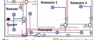
Line layout diagrams
The principle of wiring power lines is simple - the higher the load, the thicker the wire or cable should be. At the entrance to the apartment, the cable must have the largest cross-section, since the entire apartment load falls on it. For branches to distribution points and lighting, a wire of a smaller cross-section is used.
Based on these requirements, three electrical wiring options were developed:
- Daisy chain circuit (bus connection). This is the laying of a common power line with a large cross-section cable, from which branches are laid through distribution boxes to consumers;
- The radial scheme is considered more reliable. It is implemented as a supply of separate wires from the distribution board to each point of distribution or consumption. The disadvantage of the scheme is the high consumption of wire or cable;
- The last scheme is a combined one, assembled on the basis of a loop and a radial one.
In new buildings, combined wiring is used, in houses of old construction - the first two variants of circuits.
Important! You cannot hide electrical wiring in the joints and seams of walls - PUE Chapter 7.1.
Cable laying over the air
This method is simpler and requires much less financial investment. It may be necessary to install an additional support if the distance between the pole and the entry point is more than 10 m. The maximum permissible distance between the additional support and the pole is 15 m. The electrical cable is inserted into the house at a height of 2.75 m. A distribution panel is mounted on the facade, to which the electrical cable is connected . If the height of the country house does not allow direct installation, then you will need to install a curved or straight pipe stand. For more reliable fastening of the rack, stretchers are used.
Installation of hidden electrical wiring in walls
Hidden electrical wiring is installed following the following steps:
- The line for laying the electrical route is marked and the tracing is done. At this stage, you can use existing voids in the walls;
- Next, the walls are grooved according to the markings, niches are made in the walls for installing electrical sockets;
- The room is put in order;
- In places where electrical outlets are installed, mounting boxes (plastic cups for outlets) are attached. Installation areas for mounting switches are also equipped;
- The wire is inserted into the socket boxes; for the socket blocks, not a wire, but a cable is used. The length of the free ends of the wire according to the requirements of SNiP ≥ 150 mm.
Electrical wiring and cables for low-current circuits (communication lines, TV cable, surveillance systems) are supplied through separate grooves; it is allowed to lay them parallel to power lines. The cable channel should be laid without twisting the wires.
Before attaching wiring to electricity distribution points, it is necessary to secure all wiring with alabaster or plaster in grooves. The channels are leveled from above with plaster. Small cross grooves can be connected to each other with plaster immediately after laying the power lines.
If the electrical wiring diagram provides for the installation of junction boxes, then the wires. Which went into the box should first be unsoldered, all connections checked for contact and strength, the junction boxes themselves should be tightly and firmly closed.
The wire is passed into corrugated (cemented) pipes after all surfaces are plastered and puttied.
Installation of electrical sockets and switches is carried out only after completion of final repair work.
Hide the wires behind the table
A great option if you need to tidy up your computer wires. For this method, we will stock up on screws and ordinary office clips. In order not to spoil the surface of the desktop, the screws should be at least 1/4 smaller than its thickness. First, select the location for attaching the extension cord. It should be located where all necessary wires are accessible. Then we attach it to the bottom of the tabletop. To do this, it is very convenient to use wide textile adhesive tape. It is screwed to the tabletop with screws, and then an extension is attached to it.
After this, several holders are screwed to the tabletop. Then we plug the wires into an extension cord and collect them with binders in several places. To ensure that the wires do not dangle, special cable channels are used. They can be purchased at any building materials store. Thus, we put the workplace in complete order. It immediately becomes much cleaner and neater.
Wall cutting and wire laying
You can make grooves in the walls using simple hand tools - a hammer and a chisel - but it is much faster and easier to use a hammer drill or grinder.
Working with a grinder:
Two parallel recesses are cut in the wall along the wire laying line, and the insides are knocked out with a hammer drill with a flat lance. The groove is made in width depending on the thickness of the wire or cable run. The depth of the groove should be such that all wires can be plastered. The grinder is used when you need to make grooves in concrete walls.
Working with a hammer drill:
It is easier to punch brick walls directly with a hammer drill. Without using a grinder. Brick walls are much softer and the work will go much faster. There will also be much less dust.
The wire is laid in the recesses so that at least 5 mm remains to the outer surface. This will be the layer of plaster that will cover the groove.
Installation of wires in corrugated pipes
There is a special mechanism for pulling wires through the pipe. At home, you can use a cable of suitable diameter. According to SNiP, 30% of the pipe volume should remain free.
It is strictly forbidden to string low-current wires and power cables through the same pipe. It is allowed to lay lines parallel to each other. But without intersections, twisting and overlaps.
The angle of rotation of the corrugated pipe must be less than 90˚, otherwise difficulties will arise with pulling the cable.
Gasket using grooves
The methods of laying hidden wiring described above apply to the case when a house is being built and all engineering systems are just being organized.
Grooves in plaster for wiring
However, there are many cases when owners of brick houses want to replace old wiring with their own hands. In this case, additional difficulties arise.
They are due to the fact that all the old wiring is hidden under a layer of plaster and new wiring will have to be laid in this layer. In order to install it, you need to make channels in which the electrical wires will be placed.
Features of drilling grooves depend on the thickness of the plaster layer. If this layer is thicker than the wiring that will be laid, or the tubes in which the cables will be placed, then only the plaster is tapped.
In this case, you can say that you are lucky because you will not have to put in much effort. However, if the thickness of the plaster layer is insufficient, then you will have to trench the brick wall. And this is much more difficult.
The chipping of brick walls is also carried out with certain rules. So, the channel should not be wider or deeper than 25 millimeters. One groove should not be longer than three meters. Horizontal channels cannot be made on load-bearing brick walls. It is also forbidden to trench ceilings (with the exception of plaster on the ceiling).
In addition, the channels must be made in such a way that there is a minimum number of angles between the locations of the switch/socket and the junction box. Of course, it is better to make only one angle of transition from the horizontal groove to the vertical one. Wall joints are not taken into account in this case.
Installation of hidden electrical wiring behind wall panels
Wall thermal panels are not uncommon in modern housing construction. How to lay wires under them so as not to damage the surface? It is recommended to distribute the main wiring diagram under the panels in advance. The process is similar to laying cables in walls, but without gating.
Follow these recommendations from professional builders:
- Pipes are made of non-combustible materials;
- For powerful electrical appliances, special mounting boxes are used;
- It is strictly forbidden to lay wires or cables across them.
Wall thermal insulation panels are mounted on a metal profile. Holes for laying the cable are pre-drilled in the profile. Perforated metal profiles are also sold. Corrugated pipes are used to pull wires - without such protection, the wiring insulation can be damaged by the sharp edges of the profile.
What else can help in finding hidden wiring?
The searchers that can be purchased for personal use were discussed above.
But it often happens that you need to find the wiring only once and for this it is not advisable to spend money on a special device, but you still need to find the wiring.
Indicator screwdrivers.
In this case, an indicator screwdriver can come to the rescue. It is better, of course, to buy a more modern one, for example, such is the Chinese MS series of indicator screwdrivers, which have a light and sound alarm.
But you can get by with a regular probe with an LED indicator.
They work on the electrostatic principle, that is, they are able to detect the electromagnetic field emitted by live wiring.
They are very simple to use - just put your finger on a special metal window (MS indicators) or touch the tip of a screwdriver (regular indicator), and then simply move the screwdriver along the wall.
In the place where the wire is laid, such indicators will begin to signal.
The disadvantages of this method of determination include a relatively small detection depth (up to 2 cm), as well as a strong error, that is, it will not be possible to accurately detect where the cable lies.
It will only be possible to determine a channel with a width of 10 to 20 cm. But this is often enough to carry out installation work associated with drilling a wall; you just need to do everything outside the boundaries of a certain channel.
Multimeter.
You can also use a multimeter for searching.
But the device itself is not enough; you will also need a field-effect transistor (an excellent option is KP103). How to check a transistor with a multimeter, read here https://elektrikexpert.ru/proverit-tranzistor-multimetrom.html.
To get a finder, you need to connect the specified elements correctly. Such a transistor has three terminals - drain, source, and gate.
We connect the probes of a multimeter, switched to ohmmeter mode, to the first two terminals, and the polarity is not important.
The shutter will play the role of an antenna (which can be slightly lengthened).
Having built such a device, you can start searching - we move the antenna along the wall and look at the multimeter readings - any deviations in the readings will indicate the location of the cable.
Smartphone.
A smartphone with Mac or Android OS can also help with identifying hidden wiring.
For them, you can find the “Metall Detector” program or its equivalent in the application store.
The magnetic sensor built into the smartphone in combination with the specified software allows you to get a metal detector that can detect a cable hidden in the wall.
But it is worth considering that it will react to all metal elements, so it cannot be used everywhere.
The search accuracy of a smartphone is sufficient to determine the channel in which the wiring is laid.
Keep in mind
The instructions provided above are suitable if you want to make a groove in a monolithic or brick house with appropriate walls. However, today aerated concrete, wooden and plasterboard partitions can be erected inside housing. We’ll talk further about how to groove one of the non-standard wall options yourself.
When installing electrical wiring in a bathhouse or wooden house, you will encounter walls made of logs or profiled timber. Making grooves in wood is prohibited due to safety regulations, and this is not advisable, because... You will not have to chisel the log, but rather cut special recesses in it. This task will be very difficult and will take a lot of time, so in the case of wooden walls, installation of open electrical wiring is used.
If you need to lay a cable in a wooden floor, gating here, again, is impossible, so you need to consider the option of laying it under the boards behind the chipboard, insulation and other layers of the pie. In this case, the cable is laid in pipes with localization capability, that is, metal tubes. In general, electrical wiring in a wooden house is not difficult, but there are a number of nuances. Hidden electrical wiring in combustible walls and ceilings is also possible in metal pipes, but not in corrugated pipes. If you are still going to lay wiring in corrugated floors or walls made of wood and other flammable materials, you must provide protection with a 10 mm thick layer of non-combustible material. This can be plaster, alabaster, etc. (PUE 2.1.40, Chapter 2.1). We discussed this issue in more detail in the article https://samelectrik.ru/montazh-elektroprovodki-v-derevyannom-dome.html.
Open electrical wiring in a wooden garage (using wood-look cable channels)
It will also not be possible to cut horizontal and vertical lines in plasterboard walls, because... The gypsum board sheet is very thin and fragile. The cable is simply laid behind the plasterboard partition in the corrugation, between the profiles. The only thing you can do in drywall is to drill holes for sockets and light switches with a crown, as shown in the photo:
If you need to make a groove in a tiled floor (for example, in a bathroom or kitchen), there should be no difficulties; it will be most convenient to use a grinder or wall chaser. You should not punch the tiles with a hammer drill, because... You will only damage the material - the tiles will crack, after which you will have to completely replace the floor covering. Do not forget that when working with stone and tiles, you need to install a diamond blade that is designed to work with such material.
Well, the last of the popular materials is aerated concrete. You can make a groove in aerated concrete yourself using a special manual wall chaser, the cost of which does not exceed 1000 rubles (and even then this is a model from the manufacturer). Using this tool is quite simple, as you can see by watching the video tutorial below.
Working with aerated concrete
That's all I wanted to tell you about what it is - cutting walls for wiring, and how to cut a cable route with your own hands. We hope that this information was interesting and useful for you!