How to crimp a telephone cable?
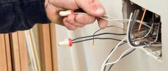
To connect the conductors to the connector blades, use a professional crimper tool.
The tool is designed to work with both RJ-45 and RJ-12 connectors. 6. During the crimping process, the contact knives are pressed into the housing, cut through the sheath of the conductors and enter between the braided wires of the multi-core cable, creating electrical contact. 7. Using a crimping tool, the strip is moved into the body. The cable is pressed against the bottom wall of the connector housing and securely mechanically fixed with a clamp in the form of a flat bar. 8. Telephone patch cords are used in telephone patch panels.
9. Telephone patch cords are used to connect sockets to telephone sets.
What is a rj45 socket for?
How to connect two light bulbs to one switch: diagram, video, instructions
This element of the fitting is designed to transmit a computer signal from one system unit to another. One of the most frequently installed devices is a combined computer-TV socket. The ease of use of this element is achieved by installing an rj11 telephone connector in one housing. Such a device allows you not only to connect your computer to your home network, but also to connect your landline phone to the network.
Before you find out how to connect such a device, you need to understand what models of computer fittings exist.
How to connect a telephone socket: diagram and installation steps
Such blocks are concentrated in one place, convenient for maintenance and hidden from prying eyes.
And broken wires will only lead to equipment malfunction.
The rest can be cut off.
After this, the wires are connected to the outlet according to the diagram. Connection RJ 11 RJ 11 has two wires, so it is easy to connect it yourself at home. The second wire comes to another contact of the socket and leaves from it the same way, but only to the second contact of the next one. It is quite flexible and can be easily mounted in corners.
Required tools and materials
Miniature knives provided in each contact will cut through the insulation and ensure reliable contact. If you are going to install a socket at home, RJ will be a good solution. Some models may not have the numbering of contacts, which is usually printed on the body of the device. Phones are connected only through two central contacts.
This type is in great demand and involves the use of 2 conductors. In the event that there are neither marks nor instructions, then you can use the guide presented below. For comparison, average prices from online stores for the products of these manufacturers are shown in the table: Manufacturer.
How to connect a telephone socket to a telephone cable: diagram
With a closed installation method, for ease of connection, the wires are made to protrude beyond the wall plane by mm. Regardless of the type of telephone socket, you will need to install a special type of power cable inside this device.
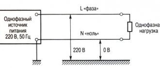
If you manage to catch the moment of an incoming call, then a variable sine wave with an amplitude of up to volts passes through the network. The ends of the supplied telephone wire are connected to them. Connection diagram of a 2-core cable with the contacts of a telephone socket. If the design of the device provides terminals, then the ends of the wire do not need to be stripped. We will tell you how to do this below. Telephone connectors
Procedure for crimping using a crimper
What are the basic requirements for a cable for heated floors: cross-section, installation and installation instructions
Wire crimp:
- Prepare the cable. You need to make sure that the cable is sufficient to reach the desired area.
- Release isolation. This must be done carefully so as not to damage the wires. To do this, step back half a centimeter from the cut and partially cut the shell. Use your hand to bend the cable at the cut site. This will cause the shell to come off. If you have a stripper, this process will not take much work. Although you need to get used to it.
- Preparation of veins. The conductors must be separated from each other and straightened. Copper conductors are soft, this is not difficult to do. The wires are laid out in a row.
- Contact crimping. The cores are loaded into the convector using a crimper without removing the insulation. The wires are inserted all the way. After this, using a press, the connector is compressed until it clicks.
- Examination. The last stage of crimping, the crimper is removed and the connection is checked. To do this, you need to try to pull the wires out of the connector. If the crimping was successful, then it is physically impossible to do this. After the physical test, it’s time for the electrical test to check the connection.
Important! For an Ethernet network, an 8-pair convector is used, even if there are only 4 cores inside!
Checking the crimped cable
How to connect two light bulbs or two lamps to one switch
So, now that we have both ends of the cable crimped, it’s time to check our creation for functionality. For this:
- plug its connectors into the corresponding ports of the cable tester or simply into two computers (or a computer and a router, for example). Make sure that the lights at the network connector blink at both the transmitter and the receiver, and the nature of this blinking should be approximately the same;
- If the tester starts to light up a red light in some place, refer to the specified wiring - perhaps it was not pressed enough. The same applies to computers - if the network card shows no signs of life, and the system does not see the connected cord, then the crimping should be done again. This is where spare connectors came in handy.
When you finally achieve a successful connection, you can safely use the resulting wire for its intended purpose. Ready!
Methods for installing a telephone socket
If you have minimal knowledge, you can connect the telephone network yourself in 5-10 minutes. There are two installation methods - open and closed. The open method involves installation on a surface without removing the finishing layer.
For example, if you have already completed a complete renovation and now need to install a telephone, then the socket is installed directly on the wallpaper or paint. The cable channel is hidden under the baseboard. The open mounting method can be carried out without mounting on the wall at all - the socket can be on the floor.
It contains 4 screws. The two closest to the connector do not need to be touched. The wire is secured in the two remaining screws. Next, the insulation is laid - the cores are attached to the clamp and pressed with screws. After this, the housing cover is closed. The work is ready.
It is important to know! All work on open installation should be carried out with gloves. It's better to use latex
There were cases of tension appearing when they tried to call the phone. At this moment you may get an electric shock. The blow will, naturally, not be fatal, but sensitive.
The hidden installation method involves laying the telephone wire before the socket is connected. In this case, its location is planned in advance.
Sometimes the wires are hidden in the wall and the socket is taken outside. Visually, this mounting method resembles standard electrical sockets. Hidden and open installation methods are called external and internal. In general, they have no fundamental differences.
Telephone socket design, communication cable arrangement
In terms of their internal structure, connectors for connecting telephones and wires for transmitting signals have little in common with electrical sockets and power lines. They differ not only structurally, but also in the installation method. To understand all the intricacies of connecting communication lines, you need to study the features of the device and the operating principle of switching devices. article: → “Connecting different types of telephone sockets.”
The telephone line current constantly changes depending on the position of the handset (off-hook or on-hook) and the state of the connector (connected or disconnected). If the device is not connected to the network, a direct current of 40-60 V flows through the line. A similar situation arises when the telephone is connected, but the handset is placed on the cradle. At the moment of the call, the voltage increases to 120 V, converting into alternating voltage. Removing the tube lowers it to a value of 6 to 12 volts.
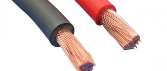
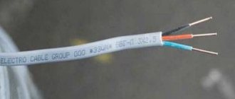
All these processes occur in a flat wire that has two copper cores. It could be compared with the PPV wire used for electrical wiring, but the core cross-section is so small that it can only be used for the specified network loads: in telephone lines, as well as in automation circuits (burglar or fire alarms).
It is impossible to confuse a telephone cable-noodle with another product in appearance
There are several types of connectors for connecting phones:
- RTShK-4 – can only be used for old communication devices;
- RJ-11 – a modern version called “euro”;
- RJ-12 is a slang name for the RJ-25 connector, which has become so widespread that for the convenience of providing information, it is used more often than the real one. In fact, such sockets do not exist, so when faced with the term RJ-12, one should mean RJ-25.
The RJ-11 telephone jack has a socket-style port for a matching plug. Outwardly, it looks like a computer socket, but upon closer examination, you will notice that their sockets differ in width (it is wider in the computer version).
The most common device options:
- invoices, also known as external ones;
- mortise, they are also internal.
There are also built-in products, but they are manufactured in the form of blocks that, as a rule, combine several types of switching devices - electrical, TV, computer and telephone. article: → “Types of sockets and recommendations for their selection and installation.”
Different types of telephone sockets can be used in different conditions
There is also a design combining RTShK-4 and RJ-11, which at a certain stage was able to solve the issue of using imported telephone sets with Euro connectors in post-Soviet territories. Now it is obsolete, although it continues to be used successfully.
Device variant combining RTShK-4 and RJ-11, suitable for different plugs
Modern telephone wires can most often be two-wire or four-wire. In this case, the core insulation has a characteristic coloring. Wires with 4 cores are used, as a rule, for office mini-PBXs, as well as for parallel connection of two devices on the secretary-director principle. In this case, RJ-12 connectors are used.
Laying a telephone cable in an apartment
Laying a telephone communication cable in an apartment, house, or office in Moscow (MSK) requires strict adherence to regulatory rules. Professional performance of work guarantees uninterrupted functioning of communications. This will allow you to save significant money in the future.
For example, a master is able to create an optimal low-current communication option for the customer, taking into account:
- network integration;
- their volume and location ( apartment
, house, group of buildings); - possibility of increasing the number of nodes: connecting additional phones;
- other parameters.
Preparing to connect
Before you start connecting yourself, you need to do some preparatory work. For installation work, you will need the socket itself, side cutters or other devices for removing insulation, a screwdriver and a tester.
Old-style sockets of the RTShK-4 brand are still in use, so periodically you have to deal with their installation or reinstallation. To connect them, you need a two-wire cable with a cross-section from 0.3 to 0.5 mm 2, for example, KSPV 2x0.5 or TRP. When installing sockets, a capacitor with a capacity of 1 microfarad was used to test the telephone line at the time of the call. It was only used for one outlet.
Currently, capacitors for sockets are not required, which helps improve the quality of telephone lines. Therefore, their installation requires a minimum of tools and materials.
Laying telephone cable, price
Our master is ready to come to you absolutely free of charge to carry out the work. The cost of calling a specialist and preliminary consultation will be included in the final amount. Prices for installation work can be seen in the “price list” section of our website.
Laying a telephone cable, the cost will ultimately depend on the size of your apartment and the cost of the materials used. Regular customers can take advantage of the discount system that applies to them. Our company’s prices are quite affordable; for a fairly low cost, you are guaranteed to receive a full range of high-quality services.
Our company has been on the market for quite a long time and has earned a reputation as a reliable team of professionals. We provide a guarantee for the work we perform and strictly adhere to SNiP and GOST standards. We will be glad to cooperate and will carry out any electrical installation work for you as soon as possible.
Below you can use the online calculator to calculate the cost of electrical installation work.
Features of color marking
During operation, it is important to connect the conductors correctly. For this purpose, color marking of the cable has been developed; each conductor has a certain shade
However, during the existence of cable products, color standards have changed several times. Therefore, it is important to familiarize yourself with each option.
Features of telephone cable installation
Mobile communications are very popular today. But, along with mobile phones, almost every home also has landline telephones, which have not yet been replaced by cellular communications. After all, it is much cheaper to make a call from a landline phone to another landline number. And older people are much more accustomed to communicating using a simple telephone than adapting to mobile phones that are difficult for them.
Therefore, even today, installing a telephone cable in an apartment is a popular service. Telephone cable is used to transmit telephone signals over a distance. This seemingly simple procedure has its own difficulties and nuances that must be taken into account. For this reason, it makes sense to invite a specialist with experience in this field to carry out the work.
Basic installation rules
The laying of communications for organizing a telephone communication system takes place according to a pre-designed project. Selecting the location of network elements - switchboard, sockets ,
relays, etc. - depends on the wiring done in the apartment, house or office space
:
the
passage of power cables and lighting lines
.
- If the telephone cable is laid parallel to power communications, the electrical installation technician leaves a distance of 50 cm between them. The lines intersect - the angle should be 90°.
- It is required to run several telephone cables in one direction - the electrician lays the conductors tightly together.
- The master mounts the distribution box on the wall (exceptions are the space above doorways and windows).
- Technology
Open cable laying requires compliance with standard distances: from the floor - more than 20 cm, to the ceiling - more than 15 cm.
- With a closed installation method, there are no such restrictions.
What to pay attention to when connecting a telephone socket
The RJ11 or RJ12 standard telephone socket contains 2 and 4 contacts. They look like small metal forks. The cable is attached between the teeth of the fork. All devices are attached to only two contacts. Professionals can use a cross-cutting knife to secure it, but at home, an ordinary kitchen knife will do. There is absolutely no need to spend money on a special tool if the connection will have to be carried out once or at most twice.
The braiding from the cable is removed approximately 4 cm. The cores should be moved apart from each other.
Many people do not buy modern RJ11 sockets, since components remain from the Soviet period. Here are some notations that will probably come in handy:
- RTShK is a Soviet standard. Now such devices are no longer produced, but a telephone set can still function today with their help. They have 4 contacts and a key;
- KSPV is a copper-based wire consisting of one core. It is covered with polyethylene insulation. In most cases, this cable comes in standard white color. It is used for internal installation in a house or apartment;
- TRP is a distribution cable designed for laying a telephone line. This wire is single-pair, which consists of a copper core insulated with polyethylene. Has a dividing base.
Telephone sockets - types and a little about their installation
Telephone sockets are included in the category of information electrical installation products. Their main purpose is to transmit data, which is why they differ from electrical outlets.
Necessary use for subscriber equipment, connection of mini-PBX, individual telephones, modems and faxes and other office equipment with the telephone network
The design of the socket depends on the presence of one or more connectors, their types and the difference in the cross-connect field.
There are several types of sockets
- RJ-11, this type of socket is marked as XP - XC demonstrates the number of positions and the number of active connected contacts.
The table shows the pinout of detachable convectors: RJ-11, RJ-12 (RJ-25), RJ-14
- RJ-11 type sockets, this marking indicates that the design uses connectors: 4p4c or 4p2c. 4p, there are 4 working contacts in the socket. If the connector is indicated as 2c and 4c, then this indicates that 2 and 4 contact blades are working. This type of connector is used to connect its handset to a telephone set.
- RJ-12 type sockets marked as 6р4с; 6р2с; 6р6с indicates that the first number indicates the number of seats, the second marked number indicates how many contact knives can be inserted into the socket. A similar connector is used in telephony for switching a telephone network line into a patch panel and for connecting the device to a telephone socket of a local network.
Rice. No. 2. The telephone network plug differs in the number of contacts involved.
For installation and correct connection of connectors, twisted cable pairs are crimped. Soldering is not used for connection. Crimping operations are performed using crimper pliers. For error-free cable connection in modern sockets, the Jung mechanism is used; the cable inserted into the device is connected by piercing without the use of additional tools and without removing the insulation which has become unnecessary. The mechanism works by turning the mounting screw ¼ turn.
Classification of telephone sockets by type of installation
There are overhead and built-in sockets, and the second type is used to maintain a presentable appearance of the interior and requires hidden installation of telephone wire.
In addition, there are sockets, distinguished by the type of configuration, which combine in their design contact sockets for connecting a telephone network and sockets for connecting a computer or modem for an Ethernet network. The security of communication and the high speed that these electrical installation products can provide, up to 100 Mbit/s, make them indispensable and in-demand devices in a modern apartment.
Installation of a telephone socket
Important: When installing telephone sockets and connecting them, you must remember that the red conductor is traditionally considered a minus, and the green conductor is a plus.
The polarity in the sockets can be checked using a multimeter; if the connection is incorrect, then you will see a minus on the display. When plugging a six-pin connector into an RC45 telephone socket with 8-pin outputs, a short circuit may occur. Without any consequences, only a 6-pin connector can be connected to a computer socket. The wire for laying a telephone line is used type TRP 2x0.4 (noodles) with a dividing strip between the conductors for safe fastening for the wire and for convenient stripping.
Currently, optical fiber is increasingly used for multi-channel communication lines. Their advantage is excellent insulation and conductivity of information. UPMK is used to secure the technological supplies of the optical cable on the supports. More details can be found here https://td.opten.spb.ru/komm/uzdelia-vnutrizonovie-MTOK?obj=100
Write comments or additions to the article, maybe I missed something. Take a look at the site map, I will be glad if you find anything else useful on my site.
elektronchic.ru
Features of color marking
During operation, it is important to connect the conductors correctly. For this purpose, color marking of the cable has been developed; each conductor has a certain shade
However, during the existence of cable products, color standards have changed several times. Therefore, it is important to familiarize yourself with each option.
Current color markings:
- Modern. Positive contact – orange-white, green-white, blue-white. Negative contacts - orange, blue, green.
- Old. Plus – green, black orange. Minus – blue, yellow, red.
- German. Positive – brown, green, pink. Negative – white, gray, yellow.
It is possible to share wires with different markings
It is important to take into account the polarity when connecting them
Telephone line repair
If a landline telephone stops working, they usually call a signalman and wait for him to arrive, often at an inconvenient time. However, if you don’t want to wait and have a desire, then you can restore the connection with your own hands.
There can be two reasons why the phone stops working: either the telephone set is broken, or the telephone line. If you have a spare telephone, connect it instead of the one that is not working; If the connection appears, then the phone is to blame for the breakdown, and if the connection does not appear, the line is to blame.
The serviceability of the line can be checked by measuring the voltage in the telephone socket. If there is no device, you need to check the reliability of the connection of the linear communication wire to the socket contacts. If the connection in the socket is reliable, then you can use the wire to trace which contacts of the plinth your line is connected to, and check the reliability of the connection to the contacts in the plinth.
If it is not possible to trace, then you can check the reliability of connecting all suitable lines to the plinth, because one of them is yours. If there is voltage at the contacts of the plinth, and your pair is connected securely, then the wire going to the telephone installation point is broken. If there is no voltage, then you need to disconnect one of the conductors going into the apartment and measure again after 5-10 minutes.
If voltage appears, it means there is a short circuit in the wire running from the plinth to the outlet in your apartment. To check this fact, it is enough to reconnect the line wire to the contacts of the plinth and measure the voltage; it should disappear again.
Installation methods
Telephone sockets can be installed in an open or closed manner. The open method means that all the decoration on the wall is preserved; the equipment is attached directly to the wallpaper or paint.
In this case, the wires are hidden in a cable channel located in the baseboard or on the wall. You can find cable channels of different colors and sizes, baseboards with a cable channel inside. Models with snap-on lids are convenient. There are also baseboards with built-in sockets. When buying them, choose those whose front panel fits well to the base, otherwise over time it will begin to lag.
Sometimes devices are mounted not on the wall, but on the floor. When connecting in an open way, they can even be glued with double-sided tape.
If the telephone socket is connected in a closed (hidden) way, the wires are laid in the channel before the socket is installed in the socket box. Sometimes the wires are laid in the wall and the socket is installed outside. Most often they use a copper single-core cable KPSV in a white polyethylene sheath or a copper single-pair cable TRP.
Most often, telephone sockets are not installed separately, but as part of an outlet block, for example, together with an electrical outlet and a switch, as in the photo.
Advice! To disguise the structure, place them behind furniture facades or behind monitors and TVs.
Wire, connector and crimper
A reliable connection is essential for safety. This will eliminate the possibility of electrical damage and will not disrupt communications. The connectors are fixed with crimpers. Each connector is designed for its own wire cross-section.
Before starting work, you need to calculate how much wire is needed. The distance between equipment should not be more than 100 meters.
Twisted pair cables have become one of the most common cables. It is qualified by different degrees of protection: grounded copper or aluminum. The number of cores in such a cable can be 8, it is called 4 pairs, or four-core - 2 pairs.
The frequency of data transmission depends on the quality of the cable. This indicator is called CAT. The higher it is, the better the transfer speed.
To work with the cable, a special RG-45 connector is required. During operation, you need to connect the conductors correctly so that the connection is established.
A crimper is a special tool for crimping a network cable. It helps connect two parts of the wire without soldering.
Where is twisted pair cable used and why is crimping needed?
The process involves installing a special connector at the end of the network cable. It is necessary to connect the cable and any device, for example, a computer, telephone, modem. The contacts on the network must be correctly connected to ensure good operating conditions for the devices.
Instructions
Various wires are used for wiring telephone communications indoors. The most widespread, especially in old houses, is the telephone distribution wire (TDW), or “noodle”. The low reliability and noise immunity of this wire are compensated by its low price, which explains its widespread use. A more modern and convenient option is a flat line telephone cord (SHTL). Each of the four conductors is individually insulated with multi-colored plastic, which makes wiring easier. All the wires are sealed in a plastic sheath, which prevents mechanical damage. When purchasing a new wire, preference should be given to SHTPL or its analogues.
Regardless of the number of conductors in the cord, only two are used for regular telephony. The rest can be used to connect telephones according to the “director-secretary” scheme or in digital mini-PBXs. If there are more than two wires and you don't know which are connected to the PBX, use a multimeter. You can also use the traditional method of checking the signal “by tongue”, but this is unsafe. At the time of the call, the voltage on the telephone line can reach 150 volts, which is enough to cause serious injury. If connectors are on both ends of the wire, use color-coded conductors. All telephones, unless otherwise indicated in the operating instructions, use two central conductors as workers. The remaining contacts in the connector remain unused.
- Stretch the internet cable
In order to crimp a telephone wire, you must first cut it straight, and then remove the outer plastic insulation at a distance of one and a half centimeters from the edge. As a result, you should have in your hands the end of the wire with multi-colored conductors sticking out. Do not remove the plastic insulation from individual conductors. Identify the two wires that are connected to the telephone exchange. Arrange the conductors in one plane so that the connected wires are in the middle. Insert the wires into the connector without disturbing their location. Push the wire into the connector until it stops. Insert the connector into the crimping pliers. Be careful not to let the wires fall out of the connector. Squeeze the handles of the pliers tightly. Remove the crimped telephone wire and check its functionality.
If you need to establish a local connection between computers, use one of the most common communication cables - twisted pair. When you don’t have such a cable at hand, but the matter is urgent, and besides, buying it will take up a significant part of your time - try making such a cable at home. This procedure is technically simple. But it will require additional knowledge in this matter.
Installation of VSSK coupling for 10 pairs
Cable preparation (cable TPPepZ 10*2*0.5).
We clean and degrease the cable sheath from both ends to 250 mm.
Repairing cable shield
It is necessary to insert the base of the screen connector under the cable sheath, between the screen and the belt insulation of the cable until it stops against the edge of the sheath. Lightly tap the shell so that the teeth engage the shell. Place the cover on the base screw and tighten both parts with one nut.
On cables with an outer diameter of less than 20 mm, a 25 mm long sheath cut must be made on the side diametrically opposite to the screen connector.
We put the screen bus on the screws of the connectors and secure it with the second nut.
Cable splicing
We evenly distribute single-core connectors around the circumference of the splice so that the diameter of the splice is the same. We use Scotchlock UY2 type connectors.
Filling the cable core with compound
Apply one turn of mastic to the cable sheath behind the screen connector. Wrap the plastic sheet evenly around the mastic ring so that the line on the sheet passes under the bottom of the joint. We wrap the ends tightly with 88T tape.
8882-A Sealing gel, package 90 ml. Designed for pouring by gravity or under pressure into cable splices for the purpose of sealing them on cables with polyethylene insulation, not filled or filled with hydrophobe, without its prior removal. 8882 is a two-part, urethane-free compound. It reliably seals the filled cable and is compatible with plastic used in telephone connectors. Compatible with polycarbonates, copper and fillers. Does not contain isocyanates. The sealant material is polybutadiene.
Let's break the packaging bridge between the components of the compound and mix them. Fill the container obtained from the plastic wrap to the level where the compound completely covers the connectors and conductors.
Unfold the corners of the plastic wrap and roll the bag into a tube from the edge down towards the splice. We wrap the edges of the plastic wrapper to the mastic with 88T tape. Wrap the joint, extending beyond the edges of the mastic, with two layers of elastic EZ vinyl tape with a 50% overlap of turns.
We wrap the entire joint with force, stepping beyond the edges of the mastic, with three layers of elastic EZ tape with a 50% overlap of turns. When winding, we step 2 cm beyond the edges of the mastic. Let's secure the end of the EZ elastic vinyl tape from unwinding using 88T tape.
Mounting the coupling housing
Slide the coupling halves onto the sprout. We wrap one layer of mastic around the central joint and the joints with the cable.
To protect the mastic, wrap the mastic tightly with two layers of 88T vinyl tape, overlapping the turns and extending 20mm beyond the edges of the mastic on each edge. We start winding with a smaller diameter.
Installation of heat shrink tubes.
Ready.
We take measurements of the installed section of the cable line.
Whether the process of localizing cable damage underground will become prohibitively expensive or not depends equally on the professionalism of the repair team, and the capabilities of the pulse locator and the quality of its performance. In this case, the proverb: “The miser pays twice” becomes especially relevant.
Subscribe to the newsletter
The quality of communication largely depends on how competently the telephone cable is crimped. To connect telephone cables to devices, mini-PBXs in offices, administrative buildings, apartments, etc., RJ-11 connectors are used, which are compatible with standard R-11/12 telephone sockets. In this article we will look at how to crimp a telephone cable using this connector.
What tools and materials are required for crimping?
Before crimping a telephone cable, you will need to purchase the following:
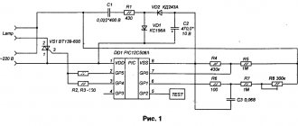
• Telephone cable (communications) - KSPV 2x0.4 (standard telephone sets) and KSPV 4x0.4 (digital programmable telephone sets). • Cleaning tool (construction or office knife). • RJ-11/12/25 connectors. • A special crimping tool - a crimper (some models already have a knife that allows you to cut the cable).
How to crimp using a crimper?
Crimping a telephone cable is most often done using a special tool - a crimper. Proceed in the following sequence:
• Remove the outer sheath from the end of the telephone wire (0.5–1 cm). The cores themselves do not require stripping, as the connector blades will cut through them. • There is nothing complicated in the layout (Fig. 2) of the KSPV 2x0.4 cable. Power and signal must be supplied to the two middle pins of the connector. In the case of KSPV 4x0.4, you can resort to direct layout (one core for each contact).
• Insert the wires all the way into the connector. It is important that from the front side the wires reach the end of the channels. • Insert the connector into the crimper and tighten it.
That's it - the telephone cable is crimped. All that remains is to remove the crimped cable from the crimp and carefully inspect the “knives” of the connector for good contact. If the connection is bad somewhere, you will need to cut the cable, use a new connector and crimp again.
If the crimping of the telephone cable “2 cores” or “4 cores” is done correctly, then you will hear the desired dial tone in the handset.
The nuances of performing crimping without a crimper
Crimping a telephone cable into 2 or 4 cores can be done without special tools. It won't be difficult to do this. So, let's look at how to crimp a telephone cable without a crimper.
To correctly crimp a “2-core” or “4-wire” telephone cable without a tool, do the following:
• Cut the required amount of cable and strip the outer sheath. • Insert the wires into the connector (2-wire - into the two middle contacts, 4-wire - one wire into each contact). They must go all the way. • Take a flathead screwdriver and use it to press in the pins one by one. • Press the screwdriver into the clamp that is present on the connector. Thanks to this, the cable will not wobble.
When crimping a telephone cable in this way, be extremely careful and attentive. This method does not always provide high quality crimping. In addition, the risk of cable damage is quite high.
Knowing how to crimp a “4-core” telephone cable or how to crimp a “2-core” telephone cable, you can easily cope with this task. You can do this with or without a crimper. The whole process will take a couple of minutes. Always take into account everything written above. Only in this case will you be able to establish high-quality telephone communication.
is one of the leaders in the sale of cable products and has warehouses located in almost all regions of the Russian Federation. After consulting with the company’s specialists, you can purchase the brand of telephone cable you need at competitive prices.
Source: cable.ru
RJ-45 crimp color scheme according to PoE IEEE 802.3af and IEEE 802.3at standards
The IEEE 802.3af PoE standard provides the ability to transmit an information signal and supply power to the device via a single twisted pair cable crimped with an RJ-45 connector. This allows you to do without an additional wire to supply the supply voltage.
Regardless of the RJ-45 compression options, voltage is supplied simultaneously from the positive terminal of the power supply to pins 4 and 5 (blue pair), and from the negative terminal to pins 7 and 8 (brown pair).
As a rule, the pinout of twisted pair cables according to the PoE IEEE 802.3af standard is used when creating video surveillance systems that use a switch, for example, the 9-port PoE switch ROKA R-KM-POE0801, in which each port has the ability to feed via RJ-45 DC voltage 12 V with power up to 30 W.
What is the correct wiring diagram for a telephone cable?
I think that everyone who has, or had, a landline telephone has been faced with the task of crimping a telephone cable. If a person is familiar with this matter, there is nothing complicated. If you have never encountered such a task before, it may seem simply impossible. But I really don’t want to call a specialist for such a small thing. Well, don’t worry, the task is quite real.
It is very inconvenient to work with such thin veins, especially if you do not have the appropriate tool, they tear very easily. Each core is enclosed in insulation of a certain color. Each wire must be connected to its own contact, but for this you need to know the connection diagram. There are two standard standards, they are called T568A and T568B. In Russia it is customary to use the second one - T568B. Although, I don’t see any particular contraindications to other standards, if there is such a need. However, choose only one scheme and stick to it on each section of the cable line.
You will need the following:
- telephone wire,
- crimping device (if not, you can rent it),
- RJ-45 connector
Cut the shell with a construction or stationery knife, remove it and the internal conductors will appear in front of you, straighten the wires and arrange them the way they should be located. Align them along the same line lengthwise and if they are different lengths, trim off the excess. Insert the wires into the connector all the way, making sure that each wire fits into its own groove. Compress and enjoy the work done.
You can also try to crimp the cable with a screwdriver, but this is a last resort; you can find tutorials on YouTube.
www.remotvet.ru
Connecting a telephone socket
Between the metal contacts, a recess is required for the power wire. If it doesn’t help, then check the connection diagram, as well as the integrity and reliability of the wire contacts. Features and rules for connecting a socket Each existing type of socket has its own connection features, but below we list the features of mounting RJ and RJ type sockets, which are in great demand. We will tell you how to do this below.
Almost all types of sockets are connected to the network using two contacts.
The line in such cases is also usually drawn in an open, external way; internal, when installed in a recess specially provided for this purpose.
Wire Color Coding Standards Different manufacturers have different color coding standards.
There is no need to wrap the joints with electrical tape. The communication socket for a low-current network is where the telephone connects to the communication network. The second type includes 4 wires, which is convenient, for example, for an office where a larger number of channels is needed.
The following types can be distinguished: Soviet model RTShK-4; modern RJs, usually used at home; modern RJs, used in offices for connecting faxes, laying a modem line and for other equipment; modern RJs, which are special-purpose connectors; universal or combined, combining two or more types of connectors, for example, RTShK-4 and RJ Connecting a telephone socket and IP telephony. How to install and connect a telephone socket?
RJ 11 connection
RJ 11 has two wires, so it’s easy to connect it yourself at home. To do this, you will need to connect the two ends of the wire with certain contacts in the socket, so that in the plug and in the socket they are located in a mirror image. For installation you need:
- two-core cables with a thickness of 0.3-0.5 mm,
- screwdrivers - flat or Phillips, depending on the type of screws, with an insulated handle,
- drill,
- insulation removal tool,
- tester,
- tool for crimping contacts - you can not use it, but crimp the contact plates with a screwdriver, but then the plug will not look so neat.
The video shows how to properly connect a telephone socket to the line.
Important! Work on connecting the socket should be carried out using rubber or latex gloves. The voltage in the low-current network reaches 60 V, dropping to 12 V when the tube is removed. If they try to call the phone, a voltage of 120 V will arise in the wires, that is, they may receive an electric shock. With such tension it is not dangerous, but unpleasant.
First of all, you need to turn off the electricity. Next, you need to remove the insulation from the wires. This is done with side cutters, pliers or a regular knife. You need to carefully remove the insulation from the wires so as not to damage the core of the telephone cable itself, otherwise it may break in the future.
Do not burn the insulation and then remove it with your fingers. You can burn yourself with hot plastic, and with this method it is difficult to remove the insulation carefully. You need to strip the wires at a distance of 4 cm from the end.
It is advisable to strip the wires generously: they are thin and fragile and can be easily damaged. The excess part, if any remains, can be easily hidden under the socket body. For closed installation, for convenience, the wires are made to protrude beyond the wall surface by 5-8 cm.
Next, use a tester to check the polarity of the wires. Typically, in telephone jacks, the red wire is positive and the green wire is negative. But it is better to check the polarity, since it is not known how the wires were located before. If it is not possible to use a tester, then connect the cables according to the diagram that comes with the device.
To check if the line is working, you need a voltmeter (multimeter). The line voltage should be 40-60 V.
After this, the wires are connected to the outlet according to the diagram. To do this, you will need a screwdriver - insert the wires into the connectors and tighten the screws, clamping them well.
If you need to install the outlet in a closed way, then first markings are applied to the wall showing where the device will be located. Then, using a puncher, holes are made according to the markings and the structure is secured with self-tapping screws. A protective casing is installed on top. At the end the device is also tested.
If you are installing a new point and there is no space for sockets on the wall, then first make a recess for them - a socket box. It is drilled out using a special crown attachment on a hammer drill with a diameter of 6-7 cm. Channels for laying wires are also drilled using a hammer drill. If there is no hammer drill, this can be done with a hammer and chisel. But such work is much longer and more labor-intensive.
After this, install the device in the socket box, making sure that the cables are not intertwined. Then the socket is secured using self-tapping screws and expansion screws. The gaps between the socket box and the wall are covered with gypsum mortar.
When the solution hardens, install the protective edging and front panel. The protective edging in modern models is attached with latches, and the front panel is fixed with screws.
Crimping diagrams and twisted pair markings
When crimping a twisted pair of 8 cores, be sure to take into account the markings of the conductors. Each connection necessarily corresponds to a specific color scheme, which requires strict adherence. Otherwise, the signal will not pass through, and the network will not function.
Lazy crimp 2 pairs
In the considered option, direct crimping of the cord is used, where not 8, but only 4 cores are involved. Therefore, this method got its name for those who do not want to bother with all the veins. However, such a connection is only suitable for low-speed networks.
This type of crimping is not recommended for use at this time. The fact is that Internet speed is constantly growing, equipment is improving, and the 4-wire circuit stops working under new conditions. Therefore, sooner or later, you will have to switch to the standard scheme. If the network was initially laid with an 8-core cable, then all that remains is to crimp the RJ connectors in a new way, and everything will work. But, if the network is equipped with a four-core cord, then it will have to be completely changed and re-laid.
Pinout for a local network with more than 2 computers
When using RJ 45 connectors, pinout for connecting more than two computers to a network is carried out according to the standard scheme. All veins are untwisted and laid from top to bottom or from left to right as shown in the figure.
The conductors are aligned, cut, and then they can be crimped. After this, each twisted pair connector is connected to its own socket.
Direct pinout is marked as 568B
Direct connection is necessary in order to connect a HUB, router or switch to a computer. This method is most widespread in Russia. It is marked as 568V, and the wiring is carried out according to the usual scheme, starting with a white-orange conductor and ending with a brown one. There is a direct crimp here, since the wires are located the same on both connectors.
Crossover pinout is marked as 568A
Another way to crimp a twisted pair cable. To connect devices of the same type, for example, two computers, a crossover circuit or crossover labeled 568A is used. In this case, the first plug is connected in the usual way, and the second is connected by replacing the orange and white-orange wires with green and white-green wires. The conductors end up upside down, which is why the circuit got its name.
Direct crimp with 4 core twisted pair double pair wire
A cable with four cores is used when installing internal networks with low speeds. With large volumes, you can save significant money, since such a cable is much cheaper than a conventional twisted pair cable with 8 cores. Crimping is performed in the sequence shown in the figure.
However, the use of such networks has a number of limitations, primarily in terms of speed. In addition, it is not possible to supply power to the device when needed.
RJ 45 twisted pair compression circuit with POE standard IEEE 802 3AF
This circuit, made using PoE technology, allows not only to transmit information signals, but also to supply power to the router, switch, adapter and other devices. For example, when connecting video cameras, a separate power cable is not required. Thus, the connector combines two functions at once - data transmission and power supply to the device. The voltage in this pinout is supplied through blue and brown conductors.
It is strictly forbidden to use twisted pair to supply 220 volts, as this can lead to unpredictable consequences. The fact is that the cross-section of the cable in the network is only 0.51 mm2 and is designed for a current of up to 1.5 A. If the current needs to be increased, two conductors are connected in parallel and then the figure increases to 3A.
Cross-circuit for pumping speed of 1 Gbit/s
The connection scheme is used in high-speed networks, up to 1 Gbit/s. Eight wires are crimped in the sequence shown in the figure.
Rollover Cable console cable crimping diagram
Each end in such a connection is crimped mirrored in relation to each other. This scheme is used to configure a switch or router using a computer.
Crimping schemes and choosing the right one
There are two known twisted pair connection schemes (pinouts): straight (568B) and crossover (568A).
Straight (Straigt) twisted pair cable pinouts connect various devices. This is a “router-computer”, “router-TV”, etc. scheme. A feature of direct crimping is the identical arrangement of cores in the contacts of both connectors.
Cross connection or crossover (Cross - Over) is required when you need to connect the same type of equipment. This is a “router - router” scheme, a “computer – computer” scheme, etc. The peculiarity is that at the first end of the cable the straight type is used, and at the second the wires intersect.
The second twisted pair crimping scheme for 8 and 4 cores has practically gone out of use. Most modern technology automatically recognizes the connection option and selects the appropriate switching method. Soon it will be possible to crimp an Internet cable only using the first method.
8 cores
The order of wires when directly crimping a network cable looks like this:
- white-orange;
- orange;
- white-green;
- blue;
- white-blue;
- green;
- white-brown;
- brown.
To cross-crimp a wire, use the following diagram:
- white-orange – white-green;
- orange – green;
- white-green – white-orange;
- blue – blue;
- white-blue – white-blue;
- green – orange;
- white-brown – white-brown;
- brown - brown.
The difference is that some of the couples here are crossed.
4 cores
A four-wire connection is typical for a direct crimping circuit of a twisted pair cable into 4 cores. It allows you to transfer information at speeds of up to 100 Mbit/sec. The connector remains the same, with eight channels, but to reduce network costs, a four-pin wire is used.
Color order for direct crimp:
- white-orange;
- orange;
- white-green;
- empty;
- empty;
- green;
- empty;
- empty.
Crossover Ethernet cable pinout or crossover with four-wire wire:
- white-orange – white-green;
- orange – green;
- white-green – white-orange;
- empty;
- empty;
- green – orange;
- empty;
- empty..
Types of cables for Internet connection
Depending on the type of provider, the cable can be routed to the subscriber in several ways. If the connection is made using the Wi-MAX, LTE or 3G standard, there may not be a cable at all.
Telephone cable
Used when connecting to the Internet using aDSL technology. The wire is used in two- and four-core wires; when using four wires, you can increase the length of the cable route and reduce interference. In some cases, a wired telephone is also connected via the same line. To connect, use a special cable modem or modem router.
Coaxial cable
Providers use this type of cable to connect cable television subscribers. Thanks to its wide bandwidth, coaxial cable transmits both data and analog TV signals without mutual interference. As with a telephone line, a special modem is used for connection.
Fiber optic
Fiber optic cable is used to connect either multi-storey buildings, with the installation of subscriber routers in the entrances, or houses in the private sector, since this type of cable transmits the signal over vast distances without reducing the signal level or interference. A converter, or interface converter, allows you to connect a router-router to such a cable using a patch cord made of ordinary twisted pair (UTP).
Twisted pair (UTP)
This is the most common and inexpensive type of connection. These cables bring the Internet to an apartment or house, and also connect client devices (computers, TV set-top boxes, printers) to the router. Cables come in four and eight cores. Four cores transmit data at speeds of up to 100 Mbit/s, and the eight-core version allows you to increase the speed tenfold.
Without additional amplifying equipment, the length of cable routes will be small (up to 100 meters). Nevertheless, a twisted pair connection is a popular type of connection due to the low cost of the wire and connectors, as well as the ability to cut the cable with or without a cheap tool. Whatever wire enters the house, the good old twisted pair will still go after the interface converter or cable modem.
Standard crimping patterns
There are two rj 45 twisted pair crimping or pinout schemes:
- straight;
- cross.
With direct crimping rj 45, the connectors (plugs) on both sides of the wire are connected according to the same circuit, but with cross crimping, the circuit changes.
Important! The speed of information transfer depends on the crossover connection option.
On the connector, the sockets for the wires are numbered and each of them is intended for a wire with a specific color, in accordance with the selected option. Option T568A has the following connection diagram:
- 1. white-green;
- 2. green;
- 3. white-orange;
- 4. blue;
- 5. white and blue;
- 6. orange;
- 7. white-brown;
- 8. brown.
Option T568B is connected according to this diagram:
- 1. white-orange;
- 2. orange;
- 3. white-green;
- 4. blue;
- 5. white and blue;
- 6. green;
- 7. white-brown;
- 8. brown.
For direct connection, the last option is mainly used; for mixed connection, both are used.
Option No. 1 - straight 8-conductor cable
This option is suitable for connecting different types of electronic devices. For example, a cable connected using this option is used to connect a computer to switches. The rj 45 plug is crimped according to version T568B on both sides of the cable.
Option No. 2 – 8-wire crossover
To connect devices of the same type, such as a computer-to-computer, a crossover is used. Crossover or cross circuit is carried out in two ways:
- data transfer speed is 100 Mbit;
- speed reaches 1000 Mbit. In the first case, the rj 45 connector is crimped at one end of the cable using option T568B, and at the other end using option T568A.
In the second case, the plug is crimped according to option T568B, and the other end in this way:
- white-green;
- green;
- white-orange;
- white-brown;
- brown;
- orange;
- blue;
- white and blue.
Advice! To connect a twisted pair cable with a shield, use a connector with a metal casing.
Option No. 3 - straight 4-wire cable
For low-speed networks, 8-pin (8-socket) plugs with four wires can be used. To do this, it is important to know which contacts should be involved. 1 and 2, 3 and 6 slots are used. Any two pairs can be taken, but it is important that the connection is the same on both ends, for example:
- white-orange is connected to 1 contact;
- k 2 – orange;
- to 3 – white-green;
- by 6 – green.
Warning! The remaining two pairs of cable cannot be used for other connections, since the contact between the cores will be broken, which will cause interference. A direct connection may be required for older electronic devices or a low-speed home network.
Option #4 – 4-wire crossover
This option is more for informational purposes, since it is not advisable to deliberately reduce the speed for modern devices. Let's look at how you can make a pinout for rg 45 - one of the names is rj 45. To get a crossover cable, just swap the connected pairs. Let's say the first connector is connected according to the diagram shown above, then the second is crimped as follows:
- 1 contact – white-green;
- Contact 2 – green;
- 3 contact – white-orange;
- Pin 6 – orange.
The purpose of direct and cross connection is the same as when using 4 pairs.
Tools and crimping technology
First, consumables are selected. It is recommended to use standard KSPV wire. For analog phones, KSPV 2x0.4 (2 cores) is used. Digital connections are made using KSPV 4x0.4 (4 contacts). In a similar SHTLp, the cores are multi-wire, which complicates the installation process. As a socket, the choice is the standard model R-11/12.
In a two-core wire, the signal and power are connected to the middle contacts. The four-wire cable is connected via a direct layout. The cross-over circuit, where the wires in pairs are swapped, is used abroad.
- a utility knife or its equivalent for cutting drywall;
- crimper, with its help the connection is crimped;
- RJ-11 connector or similar.
For a reliable connection, you need to do the following:
- Use a knife to remove the insulation. For four-core wires, strip 3 cm, for two-core wires – 1.5 cm.
- Align the conductors in one plane, trimming to 1 cm.
- Insert the conductors into the RJ-11 connector as far as they will go, checking the correct layout by color.
- Place the plug in the crimp and secure the contacts.
If the connection is not reliable enough, you can crimp it again. Upon completion, the operation of the telephone and the availability of communication are checked.
Crimping RJ-45 and RJ-11 connectors in the field
Sometimes it may happen that there is no crimper (crimping device) at hand, but it is necessary to crimp the connector. In this article we will look at how to quickly solve this problem using conventional tools.
We will need the following:
- thin flat blade screwdriver
- connector
- twisted pair wire
- knife
- scissors
- needle
How to make a connector with your own hands?
- Let's say we don't have new connectors, but we have already used ones with a piece of wire.
- Using a needle, pull out all the pressing copper terminals from the connector one by one.
- Disconnect the connector from the wire.
- We carefully return the terminals to their place.
The connector is ready.
Connector crimping technology:
RJ-45 (computer networks):
We cut off the tip of the twisted pair with scissors.
Using a knife, remove the plastic braiding by 3-4 cm and develop colored wires.
We form them into a line in the following order from left to right.
We pinch the wires with our fingers, step back 1.2 cm from the braid, and cut off the excess length with scissors.
Carefully insert the wires into the connector, observing the sequence, placing it with the latch down.
Press the connector against a hard surface so as not to break the latch.
Use a screwdriver to crimp the terminals one by one, then clamp the wire.
RJ-11 (telephone connector):
Cut off the telephone wire.
We strip the braid by 1 cm.
Aligning the wires (red-green)
We insert it into the RJ-11 connector. Pin3 - red Pin4 - green.
Using a screwdriver, first crimp the terminals, then the wire.
A connection compressed in this way is unreliable, but will help cope with the situation.
Subsequently, it is recommended to crimp the connection again using a special tool.
www.diy.ru
Connection diagrams
The method of determining polarity without a device has a number of advantages. It has been tested more than once. There are many options for color coding of wires and when installing and connecting the device, there is a possibility of even more confusion.
The telephone socket is installed according to certain patterns. Such a scheme is developed in advance. As a rule, polarity does not matter much. But some telecommunications devices may fail or function incorrectly if this is not taken into account. The device connection diagram is provided below:
In order to simplify installation, manufacturers mark the contacts (the diagram and designation must be supplied with the device). It can be in the form of numbers that are written near the contacts or on the diagram. Or the wires are designated by a certain color.
How twisted pair cable cores are correctly marked when installing and connecting a socket is indicated in the tables below:
Twisted Pair Crimping Tool
To crimp a twisted pair, a special tool is used, which, due to its versatility, allows you not only to crimp the connector (RJ-45) according to the color scheme, but also to prepare the cable for crimping: remove the insulation, cut the conductors.
PS When installing a twisted pair cable, the minimum permissible bending radius (8 outer diameters of the cable) must be maintained - strong bending can lead to an increase in external interference to the signal or lead to destruction of the sheath or damage to the cable shield.
How to properly crimp an 8-core internet cable
To prepare a twisted pair for operation, you need:
- the LAN cable itself, the length is determined according to needs, but not more than 55 m for categories 5...5e;
- side cutters (aka wire cutters) or a sharp knife for trimming insulation and cutting cables;
- RJ45 connectors and caps (the latter is not necessary, but significantly improves the quality of crimping the Internet cable);
- special pliers for crimping, they are called crimpers. By the way, on a professional tool there is an analogue of side cutters for stripping the ends of the wire;
- LAN tester.
We crimp a twisted pair of 4 cores
Crimping of twisted pair 4 cores is performed in the manufacture of patch cords for 10-100 megabit LANs, which are much more often created in apartments and small offices than gigabit ones.
Yes, such networks work great on an eight-wire “coil,” but with 10Base-T and 100Base-T transmission standards, only four conductors are involved, so why pay twice as much for a cable? We believe that there is no need and suggest mastering the technique of crimping a 4-core twisted pair cable.
4-wire crimped connector