What is SIP
First you need to understand how SIP works, what brands there are and how they differ. The abbreviated name SIP stands for Self-Supporting Insulated Wire.
Although for many, wire and cable remain synonymous. And SIP is also often called a cable. Apparently due to the fact that it is heavy and thick)
The main difference is that a wire is a metal conductor that can be solid or stranded, bare or insulated. A cable is a set of wires that have separate insulation, which are combined together and covered with a common insulating sheath. I wrote more about power cables here.
The design of the SIP wire includes phase conductors consisting of aluminum or aluminum alloys and a neutral conductor. The neutral conductor can be made entirely of aluminum alloy or have a steel core inside, coated on the outside with an aluminum alloy. Also, the wire design may contain additional cores designed to power street lighting networks.
It should be immediately noted that SIPs with main copper cores are not produced.
According to the current GOST 31946-2012, the following brands of SIPs are distinguished, intended for networks with a voltage of 380 V:
- SIP-1 has insulated phase conductors, the supporting zero conductor has no insulation.
- SIP-2 has insulated phase and neutral conductors. The zero core is the carrier. Designed mainly for installation on overhead lines (OHL) and for organizing linear branches from them.
- SIP-3 with additional protective insulation is designed for networks from 6 to 35 kV.
- SIP-4 also has insulated phase and neutral conductors, but structurally does not have a load-bearing element. The load is distributed evenly between all cores. Such wires cannot be connected to each other in overhead line spans. It is allowed to connect them only on supports.
- SIP-5 mainly differs from SIP-4 in that it is capable of operating at low temperatures. This GOST does not talk about it.
For “domestic” use (connecting private houses), in most cases, SIP-4 wire is used. Its minimum cross-section is 16 mm2, the number of cores is 2 (for single-phase connection) and 4 for three-phase.
It should be noted that flame retardant wires must be used for inputs into the building and for laying along the walls. Such wires are marked with the letter “n”. For example, SIPn-4. It is SIP with the letter “n” that is recommended in the specified GOST (Table 9a) for branching from overhead lines and for laying along the walls of buildings and structures.
I will add that from the point of view of conductivity for SIP, as well as for other types of cables and wires, the important parameter is the resistance of the core, and not its diameter or cross-section (which is essentially the same thing). I have spoken about this more than once in my articles and comments, but still most readers, when checking a core, take a caliper rather than a milliohmmeter. The maximum electrical resistance of SIP wire cores is given in GOST 31946-2012, Table 3.
Pole connection
Next, we will consider ways to route the cable from the pole to the home electrical network. The least financially expensive option is to supply electricity by air. According to the requirements of technical regulations, the height at which the cable is inserted into the building should not be lower than 2 meters 75 centimeters.
If this standard is feasible, an RCD (residual current device) is mounted on the wall. A cable is supplied to the RCD from the pole.
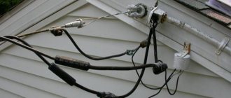
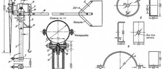
If the above height cannot be achieved, a stand made of a metal pipe is installed. The stand can be straight or in the form of a “gander” (curved). Each of the outlets has its own methods of fixation on the wall.
The distance from the pole to the entry point cannot be less than 10 meters. However, if this distance exceeds 11 meters, additional support will be required. In this case, the distance from the support to the power line should be no more than 15 meters.
For lines up to 10 meters long, copper wire with a 4 mm cross-section is used. If the distance is between 10 and 15 meters, a 6 mm section will be needed. For aluminum SIP wires, the diameter must be at least 16 millimeters.
Prices for copper wires are much higher compared to aluminum wires. Usually, in order to save money, aluminum wires are connected from the pole to the house.
The eyeliner procedure can be carried out in two ways. The first option involves tensioning a cable or support wire, to which a conductive cable is then attached. The cable is fixed using clamps.
In the second case, additional supports and fastenings are not used. Protective functions are assigned to insulators made of porcelain, glass or polymers, and to special fittings.
Thanks to the safety margin, the fittings provide reliable cable protection in case of accidents. Under powerful mechanical influences, the reinforcement may be destroyed, but the cable will retain its integrity and continue to perform its function - transporting electricity.
From the building entrance area to the electrical panel, the cable is placed in a metal pipe for safety reasons.
The main disadvantage of the air liner method is its open location, which is associated with the risk of damage. Overhanging wires create difficulties for the access of large vehicles.
Pros and cons of SIP
Advantages of SIP
The use of SIP wire allows you to eliminate several negative reasons inherent in overhead lines with bare wires.
Advantages of SIP:
- It is impossible for a short circuit to occur due to fallen branches or other objects, since the wires are insulated. This also indicates a low probability of fires.
- High mechanical strength of SIP, as a result of which its breakage is unlikely even when heavy objects fall on it.
- Possibility of reducing the dimensions of overhead lines and reducing the distance to building elements.
- Less electricity losses during transmission (we are talking about leaks to the ground, for example, through tree branches).
- Impossibility of stealing electricity by attack.
- Long service life and lower costs during operation of overhead lines.
- When constructing overhead lines, it is not necessary to install crossarms on supports.
- It is possible to lay SIPs along the facades and walls of buildings, but only at a certain distance; for this purpose, SIP facade fastening SF60 is used.
- Possibility of performing some types of work on overhead lines without removing voltage.
The fact that the SIP is insulated is a big plus. This saves not only from short circuits and theft of electricity, but also from electric shock. And not only people, but also wild animals. This photo was sent to me by a reader from the Belarusian outback:
Stork on a pole with SIP
Busel feels great even in pouring rain - thanks to the SIP insulation!
A hint for marketers - SIP can be positioned as an Eco-wire that saves the environment, this will double the price!
Disadvantages of SIP
The disadvantages include the need to train personnel who perform work on self-supporting insulated wires, as well as the cost of overhead lines, which is higher than that of lines made with bare aluminum wire.
One more drawback can be identified, which is a consequence of the advantages of SIP. Since the likelihood of interruptions in power supply due to blocked wires is reduced to zero, this means that overhead line routes are cleared less frequently than for lines with bare wires.
If wood grows into uninsulated wires, it will block them and cause a short circuit. In order to apply voltage, the tree or branches must be cut down and the wires pulled over.
In the case of SIP, everything is not so simple. Trees grow quickly and reach the SIP wires. What do you think is happening with the wires? The insulation on the wires does not wear out immediately, but it does fray. This means that by approaching such a tree on a damp day, you can feel all the delights of the effects of electric current on the human body.
Attachment to different surfaces
If the cottage or residential building is located at a short distance from the power line, then it is necessary to lay a branch based on the SIP cable, and then supply power to the building. For installation work, you will need special fasteners, the range of which depends on the design and number of supports. Clamps are installed on poles and walls. SIP cable does not require cable tensioning or trench digging.
To the post
To fix the brackets on the supports, use a perforated tape made of galvanized steel and equipped with a clamping yoke. To connect insulated cable cores into bundles, special plastic clamps are used that can withstand up to 5 years of operation. Intermediate or anchor brackets are placed on the tape to hold the main line and the branch, respectively. Elastic metal allows you to fix lines on supports with a quadrant or round profile. The strength of the clamp depends on the correct tightening of the yoke.
Why you can’t bring SIP into your home
First, the official information. According to GOST 31946-2012, according to which all SIP wire is produced in our country, “3.1 self-supporting insulated wire:
Stranded wire for
overhead power lines (...)”.
The exception, as I said, is only for the wire with the letter “n” - it can be laid along the walls of buildings from the outside. And even then – at a certain distance from the surface. The additional letter “n” in the marking indicates the fireproof design of the SIP. The polyethylene insulation of such wires is self-extinguishing and does not support combustion. However, such a wire cannot be brought into the house either.
A special feature of SIP insulation is that its insulation is designed for outdoor use. This means that it is resistant to sunlight. Cable insulation for indoor wiring must have a very low flammability, and resistance to sunlight is not important here.
Since SIP insulation is made of polyethylene, which burns with the formation of burning molten drops that set fire to everything around, the limitations on the scope of SIP use are understandable.
Some readers may have a question: why does it have to light up? After all, no one will deliberately set it on fire in the house. Here we remember the beginning of the article. Where it was said that a fire can occur at any time due to improper connection.
The main cores of SIP are made of aluminum or its alloys. As you know, aluminum is a soft metal and the contact connection tends to weaken over time. If the contact is not tightened in time, it will heat up. When heated, the contact resistance will increase, which will lead to even greater heating and cause arcing of the contacts. The problem grows like an avalanche: more heating - worse contact - more heating, etc. Aluminum “flows” inside the terminal and its tightening becomes weak.
The situation is complicated by the fact that the aluminum wire and the terminal material of the machine or meter (copper-brass alloy) have different temperature expansion coefficients.
This means that a situation may arise when the contact deteriorates and heats up so much that the SIP insulation begins to melt or catch fire. As an example, I will give a few photographs. Three-phase input to a circuit breaker in an electrical panel:
The result of incorrect connection of the SIP to the terminals of the circuit breaker. The counter also got it.
As you can see in the photo, due to poor contact and probably considerable load, the wire got hot, which led to the melting of the insulation, which began to flow down the body.
SIP insulation melted due to heating and flowed down
In the event of a fire, such insulation, continuing to flow, could possibly set fire to the entire panel. The photo clearly shows that the insulation was severely melted, and the owner decided to “fix” it with electrical tape.
SIP wires - the insulation melted due to heating
That is, the problem did not arise suddenly, they tried to eliminate it.
It is not the effect that needs to be eliminated, but the cause. And the reason here is an incorrect connection. One might say that the technology has not been followed. But more on that below.
When heated, a short circuit occurred and two wires burned out. One core remained intact (phase on pole 2). And two wires are soldered together and at the place of soldering you can see a burnt-out insulation (hole). There was little time left before the short circuit. The worst thing about this situation is that in the event of a fire, turning off the power supply would be problematic.
The same electrical panel in which the input circuit breaker was promptly replaced:
Reconnection of SIP and installation of a new input machine
Moreover, the ends of the SIP are again connected in the same way. This means the problem may repeat itself. Plus - it should be noted that the rating of the installed input circuit breaker is lower (it was 63 - now 40 A), which means that the maximum current of the SIP will be lower. But the question is: how long will it last? – remains relevant.
While we're on the subject, a couple more mistakes in this closet. After the introductory machine there is a nominal value of 63 A. It is unlikely that choosing such a large nominal value is advisable and safe. By the way, phase burnout is not as scary as zero burnout. If there is poor contact at the points 4th pole of the machine - 4th pair of meter contacts - bus N, not only a fire is possible, but also damage to single-phase household appliances. If you do not agree with me, read the articles What is a zero break in a three-phase and single-phase network and Three-phase electrical panel diagram - I answer the reader’s questions. I also described how to connect a PEN wire to the metering panel in the article Electrician in the mountains of Georgia. Well, there is no grounding, from the word “at all”.
Moreover, keeping in mind the possibility of SIP fire, it cannot be installed on flammable surfaces, even outdoors. Here is a photo sent by a reader. Here the “street” is the wall of a wooden country house:
SIP is turned on automatically on the external wall of a wooden house
The outgoing cable is not yet connected. I advised the reader to place a metal or asbestos substrate under the box, and take care of the quality of connecting the SIP to the terminals of the machine, which will be discussed below.
Sequence of actions when connecting the cable
The work can be divided into several main stages:
- first you need to roll out the cable using rollers or manually;
- then you will need to secure the cable to the house using an anchor clamp;
- then stretch the SIP between the house and the support;
- then secure the cable to the support;
- The branch power wires should be connected to the overhead line wires.
The connection can be made at a height of at least 2.75 meters above ground level. The wire should not sag between the support and the house under its own weight, but it should not be too tight.
You can also install the meter on a power line pole or on the facade of a house (you should use a box or box that will protect the meter from snow or raindrops).
How to install SIP correctly
As for how to properly install SIP to a house, you can find a lot of varied information on the Internet, which is sometimes quite contradictory. What is the best way to proceed? Where to go for help? Of course, contact the manufacturer!
We find the website of the Niled company, which modestly calls itself “the main initiator of the implementation of self-supporting insulation systems in the Russian Federation.” Here you can find technological maps for carrying out various works on lines performed by self-supporting insulated wires, which were developed together with PJSC Rosseti.
We find album No. 1, cards No. 5, No. 6. The maps describe the technology of work on connecting the input to the house from the main VLI - an isolated overhead line, that is, SIP. Specially trained personnel who have the appropriate materials and tools, as well as protective equipment, must connect the SIP from the overhead line to the house. That is, the question of choosing the best method is removed by itself. You contact the energy supply company, pay the specified amount of banknotes and wait for the team to arrive.
Connecting SIP to the house. It was smooth on paper
But it's only smooth on paper. As in any business, there are many subtleties, and connection to the line must be entrusted to a team from the energy supply organization.
Unauthorized connection of a home input to an overhead line can easily result in several months of treatment spent in a hospital bed. There is nothing to do on the support without using the appropriate tools and protective equipment. Also, you need to remember that you can be fined a hefty sum for unauthorized connection.
But even if the person reading these lines is not an electrician, it is important to navigate them. For example, what are the editing errors, who can tell?
SIP 2x16 mounted on the wall of a private house
We need to touch on one more topic - where is the equipment of the energy supply organization, and where is the subscriber equipment? To answer the question, you will have to look into the agreement concluded with the energy supply organization - the guaranteeing supplier of electricity.
The contract must indicate in black and white the boundary of the balance sheet. Formally, this is the boundary of the site, but in the Act for the delimitation of balance sheet ownership, this boundary usually runs along the accounting board. Tell us in the comments where this border is for you - at the place where the SIP is connected to the input circuit breaker, at the terminals of the meter, or at the terminals of the cable going to the house?
There is good news for new subscribers: from July 1, 2022, in accordance with Federal Law No. 522 - Federal Law, the responsibility for installation, replacement, verification, replacement and operation of electricity meters falls entirely on the electricity supplier. But as usual, there are often problems with this locally. For example, they may say “there are no meters, they will bring them in half a year.” And what? People have to agree to bet at their own expense.
In this article we will consider only the issue of electrical connection of SIP from the consumer side.
Selection and calculation of the introductory machine
To protect the input cable, we need to select a circuit breaker for input into the house, which is selected according to the rated current flowing through it when consumers are turned on. In order to determine the rated current of the input circuit breaker, it is necessary to calculate the total power of all consumers in the house. We have compiled a table showing the name and power of the consumer
| electrical appliance | Power, W |
| LCD TV | 200 |
| Fridge | 600 |
| Boiler | 2000 |
| Iron | 1500 |
| Electric kettle | 1800 |
| Microwave | 1000 |
| Computer | 500 |
| Lighting | 800 |
| Well pump | 1000 |
| Air conditioner | 400 |
| Total | 9800 |
But since consumers cannot all be turned on at the same time, the demand coefficient is used for calculations, which is equal to 0.7 when the number of receivers in the room is from 5 to 200.
Using the formula, we determine the estimated total active power of consumers:
Calculation of active power of all consumers
Next, you need to calculate the total total power of consumers in the house using the following formula:
Calculation of the total power of all consumers
where cos phi is the power factor, for residential premises it lies in the range of 0.96 - 0.98.
Now we determine the calculated current for a single-phase network using the following formula
Rated current calculation
where Unom is the rated voltage of a single-phase network equal to 220 V
Now, based on the calculated current, we select the rating of the input circuit breaker. For internal power supply of apartments and houses, modular circuit breakers of standard ratings are used:
6, 10, 16, 25, 32, 40, 50, 63 A
The rated current of the machine must be equal to or the nearest greater from the standard range.
In our case, for an introductory machine, we need a machine with a rated current of 32 A
Which wire in SIP is phase and which is zero?
I see that this question comes up quite often, but it is actually very simple. It is enough to refer to GOST for SIP, which clearly describes its colors.
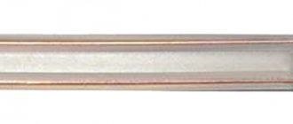
GOST 31946-2012 section 5.2.7.2: The main conductors of self-supporting insulated wires must have a distinctive marking in the form of longitudinally pressed relief strips on the insulation (...). An insulated zero load-bearing core should not have a distinctive marking. The distinctive designation can also be made in the form of colored longitudinal stripes with a width of at least 1 mm. The color of the stripes should be contrasting with black.
SIP connection color – neutral – no designation
It turns out that the phase conductors always have a longitudinal colored line, the zero (neutral) wire does not have any line. And even if there is a blue stripe on the wire, this is a phase, and not neutral, as it might seem!
But. SIP is also produced, in which all conductors are color-coded. Including blue ones. In this case, GOST R 50462-2009 , which establishes general rules for the use of certain colors and alphanumeric designations to identify conductors. There in paragraph 5.2.2 it is said that “ The neutral and middle conductors should be identified in blue. The color blue shall not be used to identify any conductor other than the grounded line conductor
(in this case, neutrals)
“
At the same time, despite the clear presentation of this issue in GOST, you must always use the rule: “Trust, but verify!” Otherwise, it will be like one of my readers - he made a metering board, connected the “blue” SIP conductor through the machine to the meter, and connected the neutral conductor directly to the GZSh, dividing it into N and PE (TN-CS grounding system). A local electrician “with 40 years of experience,” who was officially called to make the connection, without warning anyone, climbed onto the pole to connect the SIP. Having rolled off the pole after the short circuit with bulging eyes (the introductory machine was turned off!), he began to learn the materiel.
Connecting SIP to overhead lines on a support
Cable entry through a wooden house wall or foundation
If a self-supporting insulated wire or other conductor with aluminum conductors is laid from a pole to a wooden house, according to the PUE it cannot be introduced into the house: “laying cables with aluminum conductors over combustible structures is not allowed.” A switch to copper is needed. Most often, VVGng cable is used for this purpose - in non-flammable insulation.
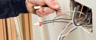
It must be remembered that terminal boxes are used to connect these two conductors; ordinary twisting is unacceptable. Directly connected copper and aluminum enter into an active chemical reaction, quickly and strongly oxidize, which worsens the contact. As a result, even with minor loads, a spark appears at the connection point, and this is a direct path to a fire. Therefore, the use of terminal boxes is mandatory. They are available in a sealed case, and some are open. For outdoor use, of course, sealed ones are better; you can also install open ones in the house.
How to connect copper and aluminum wire
But that's not all. The power cable can only be routed through a wooden wall through a thick-walled steel pipe. The diameter of the pipe must be at least 4 times the outer diameter of the wire. The wall thickness is standardized (SP 31-110-2003) and must be no less than:
- 2.8 mm for a cable with a core cross-section of 4 sq. mm
- 3.2 mm for cables with conductors 6-10 sq. mm.
It is advisable to position the entrance with a reverse slope so that water does not flow inside. To seal entry and exit points, as well as to ensure electrical safety, you can use asbestos, rubber or plastic plugs. The edges of the pipe will need to be carefully processed and sanded until completely smooth so that the cable does not fray and its sheath is not damaged.
Entering an electrical cable through a wooden wall of a house
To calm down and increase reliability, the section that will be inside the pipe can be wrapped with asbestos thread or other insulating material. It can also fill the space inside the pipe to prevent insects from settling there. Another option is to fill the pipe with cement or alabaster mortar.
Read about how to make wiring in a wooden house here.
When entering through the foundation, the situation is slightly different: the structure is no longer considered combustible, so plastic embeds can be used. They are installed at the stage of manufacturing the strip foundation. In this case, the passage for the cable differs depending on whether the cable enters a wet or dry room.
Entering an electrical cable through the foundation of a house
The spare parts necessary for organizing the safe entry of electricians into the house do not cost very much, but significantly increase the reliability, electrical and fire safety of your home. The designs are quite simple; you can handle their construction with your own hands.
Examples of connecting SIP to a house
Well, the whole connection process is shown in Dmitry’s video, Electrician’s Notes channel:
The conclusion of the article is simple. Long-term trouble-free operation is guaranteed only if the SIP is correctly connected. But such a connection is the most complex and responsible in the entire house, and requires careful preparation and high qualifications.
I ask readers to vote - which method of connecting SIP do you use?
Thank you all for your attention, I look forward to questions and criticism in the comments!
Grounding board and surge protector on the facade of the house. We solve all problems with one shield.
In general, this option is quite established in my mind and now I talk about it at all consultations on shields. And I myself liked this idea in the style of “Damn! How come I forgot about you?” To understand what I’m getting at, let’s write down the problems that we need to solve when introducing electricity into the house:
- Grounding and lightning protection circuit . It is the contour , and not the notorious triangle that everyone loves so much. If you are doing lightning protection, then you need to drive grounding conductors into at least two, or better yet, four corners of the house and tie it all into a single strip. If you don’t, then it’s enough to plug in one ground electrode with control of the circuit resistance.
- PE input from the ground loop into the shield . Most often, the ground loop itself is made of a steel strip or wire. It is clear that dragging her into the shield is stupid. How can I get it into a white and beautiful AT/U series shield, for example? You can also tell me to weld it to the shield body, heh. Therefore, somewhere on the street/basement, a bolt is welded to the strip, to which an ordinary PuV/PuGV copper wire with a cross-section of 10 square meters is screwed through a TML tip, which is then brought into the house. Such a connection must be somehow protected from earth, moisture and made serviceable.
- External disconnector in case of fire or emergency . It would be nice if there was a disconnect switch somewhere outside the house that could be used to turn off the house.
- SPDs . They need two things (in the toughest version): a metal shield, where they can safely and harmlessly bang or catch fire, and PE as close as possible to the ground loop. And between the SPDs and the shield that we protect with them (our shield at home), it is also advisable to make some distance (several meters of cable).
- Transition from SIP to copper . We have already talked about this: SIP cannot be brought into the house.
What are we doing? At first it seems that I wrote out a list of points that contradict each other. How the hell do you switch from SIP to copper and immediately install SPDs and also connect a strip from the circuit?
So here’s a good and competent (in my opinion) solution: a metal input panel on the facade of the house! This is not a shield for the meter (but it can be combined with it), but a special shield where SPDs can be installed, SIPs in a metal pipe and a steel strip from the ground loop can be installed.
It is most convenient to make such a shield based on the ST series from DKC. Here is the shield that I made for a set of shields in Pushkino:
Shield for main protection and surge protection devices on the facade of the house
Here we have the main ground bus (GZB), to which PE will come from the ground loop and a number of “Input-Output” terminals (terminals of 16 squares, connected in pairs by jumpers), which are needed to connect the input cable from the ground. , input cable to the house and make a branch for installation of SPDs inside this panel. The shield itself will be located on the wall of the house.
And here is another example of such panels (metering for a pole and surge protection for the facade) for a house in Gribanovo:
The metering panel consists of an input machine, a meter and a voltmeter
The beauty of this idea is that we are not trying to cram brutal and voluminous things into our beautiful DIN-rack system (as was the case, for example, in the panel in Tomilino), but are bringing everything voluminous to the facade of the house. And a three- or five-core cable will already arrive in the shield (cabinet) of the house, and in that shield it will be possible to operate in exactly the same way as in an apartment – just take the power and use it, without thinking about any grounding systems.
A small metering panel and an SPD panel for this panel (Gribanovo)
In the end, we can say this: if you know that you will never need any SPDs, lightning protection and other amenities, then switch from SIP to copper on the facade of the house and install it in the house right away. If you want to make a reserve for the future, then organize yourself such a shield on the wall (facade) of the house and drag the input from the ground loop and the input from the pole there. And in the future it will be possible to turn around in this shield.
It so happened that Kirich Funt was redoing another input from his relatives, but in a different house. And that’s where we made such a shield on the facade with a reserve for the future.
DKC ST series panel on the facade of a house for switching from SIP to copper, grounding, SPD and metering (Funt)
The air input is transferred using compresses to two cables VVG-ng-LS 1×10, which are then lowered in a pipe to the shield on the wall.
Transition from input to VVG cables (Funt)
The shield looks like this for now. If in the future you need to add SPDs or something else here, then there is a place.
DKC ST series panel on the facade of a house for switching from SIP to copper, grounding, SPD and metering (Funt)