The appearance of wires with an integrated load-bearing part has made it possible to increase the resistance of overhead power lines to external influences. When installing a SIP cable from a pole to a house, it is necessary to use anchors that securely hold the main line. If installed correctly, the wiring will last at least 25 years. Violations of technology lead to power failures or fires.
What is SIP cable
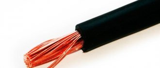
Self-supporting insulated wire is intended for organizing overhead power lines or creating lighting networks. Depending on the cross-section and insulator, the cable is designed for voltages from 600 V to 35 kV. The product was developed in the 60s. last century in Finland as an alternative to classic lines suspended on a steel cable.
The insulator is made of cross-linked polyethylene, resistant to temperature changes and ultraviolet light (the neutral or supporting core may not be equipped with a protective coating).
Varieties and differences
In accordance with the GOST 31946-2012 standard, several types of cables are produced in Russia (all equipped with aluminum conductors):
- SIP-1, designed for voltages up to 380 V and without an insulator on the supporting core;
- SIP-2, used in lines with voltages up to 380 V and equipped with a protective layer on the supporting core;
- SIP-3, designed for up to 20 or 32 kV (depending on the thickness of the insulator - 2.3 and 3.5 mm, respectively);
- SIP-4, which does not have a zero load-bearing core and consists of 2 or 4 cores (there are modifications with additional wires for organizing lighting);
- SIP-5, which differs from SIP-4 insulator made of light-stabilized polyethylene.
Reading Markings
The designation SIP stands for “self-supporting insulated wire”, the number indicates the type of cable. There are modifications with letters to mark special characteristics (for example, the letter “g” is used for a sealed cable model, and “n” is used for products with a flame retardant insulator). Standard insulation can withstand prolonged heating up to +90°C. There is a modification marked “t”, the protective layer is not destroyed at +120°C.
Both cable options are designed to heat up to +250°C during a short circuit.
Advantages and disadvantages
Main advantages of the carrier cable:
- the presence of insulation prevents short circuits when foreign objects fall (for example, broken tree branches);
- the supporting core increases the resistance of the line to breaks;
- the dimensions of the overhead line are reduced and the distance from the pole to the wall of the building is reduced;
- protection of the main line from theft of electricity is ensured by installing additional cables;
- long service life (at least 40 years);
- the smooth surface protects the highway from sticking wet snow;
- It is possible to carry out part of the installation work without turning off the voltage.
Product shortcomings noted by installation teams:
- the need to train personnel in working with cables of the SIP series;
- increased cost (compared to products with bare cores);
- risk of damage to the insulator due to prolonged contact with foreign objects;
- increased specific gravity due to the use of a load-bearing core and a thick insulator;
- flammability of the protective layer, limiting the use of products indoors.
Which one is suitable for connecting to the house?
For connection to a residential building or cottage with a load power of up to 3–4 kW, a 2-core SIP-4 cable with a cross-section of 16 mm² is suitable. If the building has heating boilers or household appliances with high energy consumption, then a 4-core wire rated for 380 V should be used.
In both cases, it is necessary to organize a separate grounding circuit to protect people from electric shock due to insulation breakdown.
Security measures
Before securing the wire, you should stock up on a mounting belt. There must be people nearby for backup. Work is carried out only in dry weather.
To carry out the work, you need to wear long sleeves and pants. Shoes should have good rubber soles.
The voltage must be turned off; if it is present, installation work can be life-threatening. Before lifting onto the support, you should check its stability; do not grab the pins and hooks present on the support.
When choosing a ladder, you need to pay attention to the fact that its length does not exceed 5 meters, and the angle of inclination is from 70 to 75 degrees. When working from a cradle, be sure to wear a helmet and a fastened belt.
Note! If you manage to turn off the power, you need to post a warning sign and close the substation or switchboard. Next, you should check the absence of voltage using a probe
In conclusion, it should be noted that SIP grade material is the next generation of wires for overhead power lines, significantly increasing the efficiency of their operation. In domestic use it is mainly used when laying lines from the transformer to the consumer and making branches from them. One of the main advantages when using it is the ease of installation and operation, which allows a person to operate it without much experience in such work. But in any case, we must remember that qualified electricians must install and extend electrical wiring to the network.
Selection of fittings for installation
When selecting components, take into account the facade material:
- Construction nails or screws are used for fastening to a wooden surface or plaster. Screws provide increased strength, but holes must be drilled into the material before installation.
- For concrete or brick structures, take plastic dowels and insert them into pre-drilled holes. If there is decorative trim on the surface of the wall, then it is necessary to install an amplifier under it, rigidly attaching it to the base. Otherwise, with a gust of wind, the cable will tear off the clamps and part of the building’s cladding.
Fasteners for SIP
To install a line of SIP series cables, use:
- anchor, support and intermediate clamps;
- brackets and mounting hooks;
- yokes and clamps for holding metal tape;
- insulated staples;
- spiral knits;
- die and mounting clamps;
- piercing and branch couplings;
- rollers and auxiliary fittings (for example, protective caps for cut cable lugs).
Clamps
To connect several cables into a single line, special clamps are used that are characterized by increased strength.
The design has an extended clasp that holds the line when branches fall. The clamps are made of plastic that does not lose strength when exposed to ultraviolet radiation or when the temperature drops to -50°C and below. Do not use standard cable ties, which will burst after 6–8 months of being outdoors.
Anchor clamps
To hold the SIP line on the wall, anchor clamps made of aluminum alloy and reinforced polyamide are used. The mounts are designed to withstand exposure to sunlight and low air temperatures. The clamps differ in maximum breaking load, cross-section and number of cores, and are suitable for organizing subscriber branches of power supply lines. The wedge clamp holds the cable and does not destroy the protective insulation.
Brackets
Brackets are used to hold wires on supports or walls. The use of existing structures (for example, mounting loops or reinforcement pins) is not permitted. The clamp is attached to the poles using a metal bandage tape clamped with a yoke. To make the clamp, stainless or galvanized steel is used, the edges of which undergo a machining cycle. The tape is characterized by increased elasticity and is supplied in coils with a length of 25 m. A special tool is required for installation and tightening with a yoke.
The fittings for fixing SIPs are made of glass fiber reinforced polyamide. Products vary in size, configuration and maximum load. The brackets can withstand cooling down to -60°C without loss of strength and are not destroyed under the influence of ultraviolet radiation. Fastening elements are designed for installation at sub-zero air temperatures.
There is reinforced fittings made of aluminum alloy using high pressure casting technology.
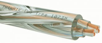
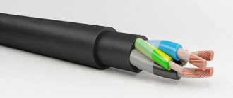
Connection of SIP with VVG cable
When introducing an electrical line into a structure, VVG cable or another similar brand of copper conductor is most often used. Direct contact of copper and aluminum conductors during installation is extremely undesirable. In this case, increased resistance to electric current occurs at the junction, which leads to overheating of the conductors, accelerated corrosion and destruction. Breaking the contact can lead to various negative consequences, including a fire. To prevent this from happening, special methods should be used to separate copper and aluminum conductors from each other.
The simplest of them is to connect a copper and aluminum core using a threaded connection. For this option you will need a steel bolt with a nut of suitable diameter, several simple washers and one engraving washer. Installation of such a connection is very simple: a washer is installed between dissimilar conductors to prevent direct contact of copper with aluminum. It is advisable to choose washers coated with pure tin or solder based on it. After tightening the bolt, the connection must be wrapped with insulating tape. This method is very simple, but extremely unreliable, so it is practically not used.
For a better and more reliable connection of SIP with copper cable, completely different methods are used, which are performed using specially designed connecting elements, such as piercing clamps, monolithic aluminum-copper sleeves and branching clamps. Let's consider each option separately.
- Piercing clamps. With this method, the insulation from the cores of the connected cables is not removed. A copper and aluminum conductor with an insulating layer is inserted into the corresponding hole in the clamp, after which the entire structure is tightened with a threaded connection. Tightening can be done either with one top bolt or with separate bots for each core of the connected cables. The body of the piercing clamp is made of durable polymer material with glass fiber reinforcement. It provides reliable protection to the connection from the effects of negative environmental factors.
- Branching compressions. Among experts they are called “nuts”. These connecting elements have in their design three bimetallic plates and tightening bolts, which are enclosed in a protective housing. To connect SIP to copper cable, you need to remove the insulation from the cores, insert it between the plates and secure with bolts. The use of clamps is more preferable for aluminum cores of self-supporting wires, since they are very sensitive to the notches that arise from the spikes of piercing clamps.
- Bimetallic sleeves. These connecting elements are made of copper and aluminum parts combined into one monolithic structure. The connection of dissimilar cores is carried out by crimping. The conductors are stripped and inserted into a sleeve, which is crimped with a special tool, thereby creating reliable contact. The connection point is sealed with a special heat-shrinkable tube filled with an insulating gel. Under the influence of high temperature, the tube contracts and reliably protects the contact from the negative influence of the external environment.
An alternative to all of the above methods of connecting self-supporting insulated wires with VVG copper cable or other brands is the direct insertion of self-supporting insulated wires into the building with a connection to the electrical panel. The rules of the PUE and the requirements of energy supply organizations do not prohibit this option, as it reduces the possibility of electricity theft.
Attachment to different surfaces
If the cottage or residential building is located at a short distance from the power line, then it is necessary to lay a branch based on the SIP cable, and then supply power to the building. For installation work, you will need special fasteners, the range of which depends on the design and number of supports. Clamps are installed on poles and walls. SIP cable does not require cable tensioning or trench digging.
To the post
To fix the brackets on the supports, use a perforated tape made of galvanized steel and equipped with a clamping yoke. To connect insulated cable cores into bundles, special plastic clamps are used that can withstand up to 5 years of operation. Intermediate or anchor brackets are placed on the tape to hold the main line and the branch, respectively. Elastic metal allows you to fix lines on supports with a quadrant or round profile. The strength of the clamp depends on the correct tightening of the yoke.
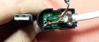
Protective caps
With any branch, wire cuts appear, which must also be reliably sealed. To seal such terminations, protective caps are usually used.
The cap on the clamp can be built-in or removable. It is better to choose punctures with built-in ones. Since, being at a height, on a support it is not always convenient to take this cap out of a bag or pocket, and often it is completely lost.
Technical characteristics and nomenclature of insulating caps:
Ensto PK99, 553, 555
Niled CE 6.35, 25.95
KVT CI
IEK CI
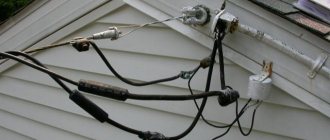
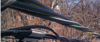
If you do not use it, then the SIP will “suck” so much moisture over time that a small puddle may form in your accounting cabinet!
Here is a clear example of the lack of SIP sealing at the entrance to the house and its consequences:
Installation of SIP from pole to house
The procedure for connecting a residential building to the power supply line using SIP must be carried out by a professional team. Installation work requires the use of special tools and a lift on the vehicle chassis. To move equipment under power lines, a permit is required, and since the wiring remains live, the operator must use protective dielectric gloves and boots.
Armature
To install the cable you need:
- piercing clamps with a protective cap (the number of elements depends on the number of wiring strands);
- anchor clamps (for example, for a standard single-phase 220 V line, 2 clamps are required for each intermediate support and wall);
- metal tape (1–1.5 m of material is required for a post);
- yokes for fixing the tape (the number depends on the number of staples);
- aluminum or plastic brackets, which are attached to the facade of the building with anchors, and to the supports using steel tape;
- plastic clamps;
- fastenings for the facade of the house.
Installation of fasteners and cable routing
Since it is unacceptable to violate the integrity of the power line support, steel tapes are used to install the brackets. The clamps are arranged in 2 rows and tightened with yokes. The wedge is removed from the anchor clamp and pulled through the resulting cable channel. The spacer is then hammered back in and the clamp is mounted on the wire bracket on the bracket. To correct the sag, a dynamometer is used, since weak or excessive tension causes destruction of the insulation and conductors.
To create a branch, piercing clamps are used, allowing work to be carried out without turning off the power supply. The exposed ends of the wiring are covered with sealed caps, and the wires are tied together with clamps into bundles. If the clamp had to be removed during the work, reuse of the product is prohibited. The SIP branch is taken to the side of the house, the bracket is secured to the facade with screws or bolts. The line between the pole and the building must be located at a height of 2.75 m and have no sag. The distance from the support to the building is no more than 25 m.
Façade layout
Since the shell of standard SIP wires supports combustion, the line is not laid out along the facade. It is allowed to fix SIPn series products equipped with non-combustible insulation on the walls. At the place where the power line is attached to the facade, copper conductors are connected to aluminum conductors using bimetallic sleeves. The cable can be brought into the building through a pipe made of plastic or metal.
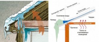
The location of the channel should prevent precipitation or condensation from penetrating into the structure.
Wire extension
To lengthen SIPs, couplings with a metal sleeve that is deformed with pliers or a press are used. For cables with an integrated load-bearing conductor, joining in the span is allowed. For SIP-4, which does not have a power core, the connection is made only on a support. It is allowed to join the segments using a piercing clamp for phase conductors and a die with a screw for the carrier line (if available).
Connecting private houses with SIP wire
Introducing electricity into a house via a self-supporting insulated wire, although it solves a lot of problems, does not relieve the obligation to comply with the requirements of the PUE for the introduction of electricity into the house. But they do not have separate instructions for SIP wires.
Connecting the cable to the SIP wire
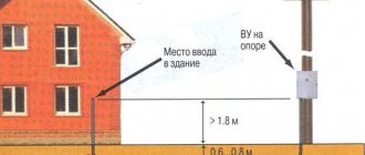
- One of the main requirements determined by clause 2.1.79 of the PUE is the entry height. It must be at least 2.75 meters. In this case, there must be a distance of at least 20 cm to the slopes of the roof or other protruding parts of the house.
Note! If the height of your house does not allow you to meet these requirements, then entry through the roofs is allowed. In this case, to achieve the required height, it is possible to install additional fasteners. Typically, a steel pipe is used for this, through which the wire is laid into the house. It protrudes to the required height.
- Also, clause 2.1.75 of the PUE normalizes the distances to wires from windows and balconies. Above the window this distance should be at least 50 cm, below the window 1 meter, and on the vertical plane no closer than 75 cm. Moreover, the distance to the balcony on all sides should be at least 1 meter.
- Having chosen a place to attach the wires, you can proceed directly to installation. The instructions for fastening SIP wires recommend the use of special fittings. These include special anchor brackets that are attached to the wall using dowel nails. An anchor clamp is attached to this bracket, which holds the wires using internal wedges.
The SIP wire is attached to the house with special fittings
- Having secured the wire between the pole and the house, you can proceed directly to entering the house. There may be several possible options here. If the input machine and the meter are located on the wall of the house, then it is better to supply electricity only to the input machine using a SIP wire. It is better to do the rest of the wiring with a cable.
- If the input machine and the meter are located in a distribution box inside the house, then you can either connect the cable to the SIP wire, or introduce electricity into the house using the SIP wire. In any case, the input requirements are the same for all of the options given.
- Wire entry into the house must be carried out in metal boxes, pipes or flexible hoses. Typically a steel pipe is used. According to clause 2.1.78 of the PUE, it should be ensured that there is no possibility of accumulation and ingress of moisture.
Note! When laying a wire or cable vertically along the wall of a wooden house, metal boxes, pipes or corrugations should be used to protect the wall of the house from fire. As a last resort, there should be a lining of asbestos sheet between the wire and the wall.
Features of SIP laying
Cables of the SIP series are designed only for aerial installation in open space (in accordance with the requirements of GOST R 52373-2005). The line is laid along the supports, providing a safe gap between the wire and the ground, and then stretched to the facade of a residential or industrial facility. It is not allowed to lay SIP underground, in closed pipes or cable ducts, or indoors.
To the intermediate support
If the distance from the power line pole to the facade of the building is more than 25 m, then the installation of an intermediate support is necessary. A bracket is fixed to the risers with metal tapes, onto which a pair of anchor clamps are placed. The laid cable is pulled with a hand winch and secured with wedges, leaving a small loop between the fasteners. There are special hangers for intermediate supports, equipped with clamps to prevent the wiring from shifting under the influence of wind.
To the load-bearing wall of the building
The line is drawn to the facade and secured using an anchor clamp located on the bracket. The base is fixed to the partition using screws or dowels, placing relief washers under the screw heads. If the building is built using frame technology, then the bracket is placed on a power beam. For fastening, use cap screws (nails should not be used due to insufficient connection strength).
Safety precautions
Basic safety requirements when laying SIP cables:
- Do not carry out work in low light or high humidity (for example, during rain or fog).
- For installation, use serviceable tools and components that have certificates of compliance with standard requirements.
- Do not use components that have visible damage (for example, cracks or breaks in the insulation) or are not intended for the cable being used.
- Carry out installation in protective dielectric clothing. Equipment handles must protect the operator from electric shock. To insulate live lines, use special overlays. When performing work at height using lifting equipment, a work permit is required. In this case, installation can only be carried out by professional teams.
Entering the house
In the case when the metering device is located indoors and the issued Technical Conditions allow this option, a dilemma arises: install the SIP inside the building and connect directly to the metering cabinet, or make the transition to VVGng cable before entering the house? Both options are possible in principle, but the following nuances should be taken into account. The SIP shell does not have sufficient fire resistance compared to the VVGng cable, therefore, it is undesirable to run this wire inside, especially if the house is wooden. On the other hand, energy sales representatives are unlikely to accept a wire connection located before the meter. There are two ways to get out of this situation:
- Input a solid SIP cable using metal pipes and corrugated hoses, treating it with one of the fire retardant compounds in the form of paint or paste;
- On the outer wall, before entering the house, install a circuit breaker, connect the SIP to the input, and connect the cable to the output, going inside the room to the meter. The switch should be placed in a sealable box.
The second option looks preferable, since: firstly, a material with high fire resistance is used indoors, and secondly, a section of the cable hidden from view, where it passes through the wall, is protected by an automatic machine. In this case, an automatic input to the meter in the metering panel is no longer required.
Installation errors
Common mistakes when installing SIP wires:
- Insufficient or excessive line tension, leading to increased load and premature failure of the load-bearing core or insulation. To ensure the required cable slack, use a dynamometer built into the hand winch.
- Repeated use of piercing clamps that does not allow the cable to be properly secured. SIP fasteners are disposable and must be disposed of if removed.
- Weak tightening of steel bands. Under the influence of temperature changes or wind, the brackets begin to slide along the surface of the pole. The defect can be easily eliminated by tightening the clamp with a special tool.
When laying wires, you should check the condition of the insulation: damage to the sheath leads to short circuits or electric shock to people. The cable is unwound on a surface without sharp objects. If tears are detected on the protective layer, the defective area is cut out. To join pieces of SIP, crimp sleeves are used, followed by insulation of the coupling. The use of artisanal connection methods (for example, twisting of cores) is strictly prohibited.
Installation sequence
When tightening the shear nut, such force must be applied that the clamp teeth:
- did not damage the main core of the SIP
- pierced but did not cut the insulation
- retained the load-bearing capacity of the core at 80% of the original
Ensto products, thanks to the pyramidal shape of the teeth and their staggered arrangement, do this better than many others.
You can see tensile testing of SIP after its cores have been pierced with clamps of different brands.
At the end, the connected soldered SIP is bent to the main one and pulled to it with a tie. This is done so that in the wind the contact is not subjected to mechanical stress and does not break off in the future.