Cable selection
To connect the antenna to a TV or digital set-top box, a coaxial cable with a resistance of 75 Ohms is required. There are many brands from different manufacturers on the market. Which to choose?
Start with the core type.
To transmit a TV signal from an antenna to a TV receiver, cables are used in which the central core is made:
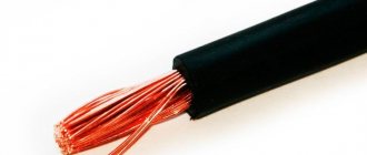
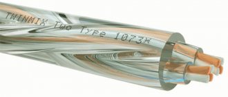
- Made from pure copper. Used for satellite television systems: the signal transmitted from space has extremely low power, and any losses are inappropriate here. Copper has very low resistance.
- With copper plating. The central core is steel, but covered on top with a thin layer of copper. Such cables are used for terrestrial television systems: signal loss is greater, but not critical, and copper-plated steel costs almost 2 times less.
When choosing a cable, it is important to consider:
- Type of signal being transmitted. “Brand” brands of cables are best used for satellite TV antennas. For broadcasting or cable wiring, simple domestic ones are sufficient.
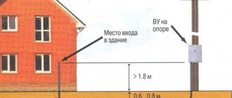
- Length of the route. Even “premium” brands have internal resistance, and the longer the signal path, the greater the loss. At distances up to 5 m, this can be neglected, but when connecting an external antenna on a high mast, the distance will affect it.
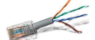
- The thickness of the central core. Standard cables have a core 1 mm thick. There are also thinner cords with a half-millimeter core. They are more convenient to install, but they are more difficult to connect to devices, and resistance losses are often higher.
- Possible obstacles on the installation path. If there are sources of interference nearby (alarm lines, electrical wiring, etc.), it is better to buy an option with maximum shielding.
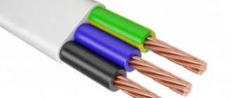
- Outer shell material. The cable is insulated from the outside using black PVC or white polyethylene. The difference indoors is small, but for outdoor work craftsmen recommend more reliable PVC.
Among the brands of cables used for television antennas, the most popular are the following:
- RG 6. Product of joint Russian-Chinese production. Inexpensive, but high-quality, shielded, with a 1 mm central core made of steel or copper, aluminum braid and PVC sheath.
- RK 75. A purely Russian analogue of RG 6, produced since Soviet times. It has a copper central core with a diameter of 1 mm, a copper braid or a double screen made of tinned copper and aluminum lavsan. Can be used both for broadcasting terrestrial or cable TV, and for connecting satellite antennas (with a double screen).
- RG 59. Thin and light cable with a 0.5 mm core. It is universal, but due to the high resistance of the wires it is unsuitable for transmitting a signal over a distance of more than 200 m.
- SAT 50. Italian, with a millimeter core and a two-layer reinforced braid of copper and tin. It has a high shielding coefficient - up to 60 dB.
How to connect an antenna television amplifier to a power supply
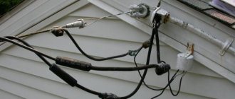
There are places where the television signal arrives in very low quality. In such cases, you have to use an external antenna, on the vibrator of which the antenna amplifier is located. It allows you to strengthen the signal even at a distance of 100 km from the tower.
Widely used amplifiers are SWA amplifiers. They have a low price and provide sufficient reliability. They have different gains and are designed for different ranges of channels. In the decimeter range, the gain is 34-43 dB and 10-15 dB in the meter range. In the photo below you can see the amplifier model SWA-555/LUX.
The SWA signal amplifier operates from a constant 12 V power supply. There is a circuit that allows voltage to be supplied to the amplifier via a coaxial cable along with the signal. On the market you can find an adapter that is also a power supply that solves the problem. It is shown in the photo below.
Connecting the adapter does not require any skills. We insert the wire that goes to the TV into one coaxial cable, and the antenna wire into the other. The adapter is installed into the outlet. It is not possible to mix up the wires, since there are different connectors at their ends.
Electrical circuit diagram of the power supply with adapter
The adapter shown in the photo above is assembled according to the classical scheme. The alternating voltage of the 220 V network is supplied to T1 (transformer), which in turn reduces it to 12 V - 15 V. VD1-VD4 (diode bridge) will perform the function of a voltage rectifier. To smooth out ripples, capacitor C1 is used. After which a constant voltage is obtained, the value of which is about 16 V. Then it goes to DA1 (integrated stabilizer).
An LC filter is made on elements C3, L1. It is installed at the receiver input. It eliminates the loss of DC voltage and loss of video signal.
L1 (choke) prevents the high-frequency signal from flowing into the power supply circuit. At the same time, direct current flows freely to the central core of the TV cable, which comes from the amplifier. C3 (capacitor) prevents DC current from flowing from the power source to the TV input. There is no signal loss in this case.
To make your own power supply, you can use various types of parts. Any transformer can be used with an output voltage of 15-18 V. This is due to the fact that the antenna amplifier does not exceed a current consumption of more than 2 W and 150 mA. As a choke, you can use a piece of dielectric, for example textolite, the width of which is 5 mm. From 25 to 30 turns of enameled copper wire are wound around it.
How to make your own adapter for supplying power to an antenna amplifier
In order to make an adapter designed to supply voltage to the antenna amplifier, I did not install a connector under the power supply. I decided to use one connector to connect the F-plug. To do this, it was necessary to remove one transformer. The number of connected TVs has decreased to two.
As a result, the concept has undergone changes.
Crab diagram for two TVs.
Before using the adapter for its intended purpose, you should install the LC filter in the crab. The crab body is made of duralumin, so I made a brass terminal. It was secured to the body using a screw and a shaped nut.
Antenna plug selection
When you have selected the desired option, connect the antenna cable correctly. You can do this in the following ways:
- Soldering. Only suitable for installing homemade TV antennas. We don't recommend it.
- F-plug. Suitable for connecting antennas for both digital and analogue television. Structurally, it is a washer that is screwed onto the end of the cable, where the outer insulation has been stripped and the braid and screen have been bent. The plug crimps the bent shielding elements, and the exposed central core is connected to the signal slot. We recommend!
- Old style plug. They were produced back in Soviet times. It differs from the F-plug in that it requires complete disassembly for installation. It has greater rigidity, and when assembled correctly, the strength is higher than modern ones. It is permissible to use.
Antenna cable assembly
The F-plug is mounted on the cable as follows:
- Take the connecting end and carefully remove it from the outer insulation at a distance of about 1 cm from the edge.
- Carefully wrap the exposed braid and foil screen back onto the part of the cable where the outer sheath is still intact.
- Cut and remove the freed portion of the inner insulation to expose the center core.
- Screw the F-plug onto the wrapped braid.
- Cut the central core with wire cutters so that about 2–3 mm of wire remains sticking out.
- Screw the second part, the adapter, onto the half of the plug that has already been put on the cable until it stops. This is not a required component, but using a “dual-layer” plug improves contact between the wire and the equipment.
If you need to connect an old-style plug to a cable, the process depends on its design.
But most often it looks like this:
- Disassemble the plug by unscrewing the metal contact from the plastic housing.
- Immediately put the unscrewed housing on the cable - this makes it easier to continue working.
- Cut off about 1 cm of the outer sheath of the wire, remove the insulation.
- Carefully trim the shielding braid by 4–5 mm.
- At the place where the braid was cut, carefully strip off the inner insulation so that the central core is exposed.
- Insert the central core into the socket of the metal part of the plug. Using pliers, gently but firmly squeeze the petals around the exposed shielding shell. Here you need to make sure that the braid does not touch the central core.
- Screw in the center core fixing screw.
- Screw the plastic shell onto the metal part. The plug is ready.
Connecting the antenna to the TV
Typically, the antenna jack is located on the back of the TV and is labeled “ANT”, “ANT IN” or similar. But the easiest way to identify this nest is visually. It is characterized by the following symptoms:
- ring-shaped metal edging;
- the central groove is a convexity with a hole into which either the central core itself or a protrusion inside the plug fits.
The antenna jack differs from other connectors in shape. It is physically impossible to connect anything other than the plug itself.
If the TV can receive both terrestrial and satellite signals of the DVB-S standard, it has two antenna connectors. The one intended for the satellite signal is marked as “ANT SAT”, “ANT 2 IN SATELLITE”, etc. The satellite antenna socket also has a notch in the center, but usually has an external thread for screwing the plug onto it.
Temporary connection of an antenna cable without a plug
If you urgently need to connect the antenna, but there is no plug at hand, you can do without it for a while.
A quick connection is done like this:
- the top insulation approximately 5 cm long is removed from the cable;
- the shielding braid is bent back;
- the central core is stripped of insulation and bent into a loop slightly wider than the diameter of the hole in the center of the antenna connector;
- a dielectric tube is put on the central contact (for example, from the removed insulation from the central core);
- the loop is inserted into the central contact, the braid is tucked into the connector using a screwdriver. The main thing here is to prevent contact between the central core and the shielding braid;
- if aluminum braiding is used, then it is simply inserted into the connector, and the free space is filled with small wires;
- to prevent the cable from falling out, it is tightened with a pair of sharpened matches;
- If contact has been achieved, the TV will begin to receive a signal from the antenna.
Check the result using a multimeter
Once the circuit has been designed and connected, it makes sense to test it and check the characteristics of the resulting design. To do this, you need to have a tester - a multimeter or any other similar device.
Check the following settings:
- The characteristic impedance of the cable should not exceed 75 Ohms.
- The difference between the braid of the coaxial cable and the central core should be several tens of ohms. If the device shows “0”, it means there is a break or short circuit.
- When connecting the central core and braid, the device should show infinity, that is, the maximum of the scale. But if both the braid and the core are disconnected from the antenna and shorted to each other, the result should be zero.
If all 3 tests are passed, then the amplifier is connected correctly.
Connecting the cable to an individual antenna
Depending on the connection method, individual antennas are of two types:
- The cable and plug are attached by the manufacturer. As a rule, these are indoor antennas with a short wire length;
- You must connect the cable yourself.
In the latter case, the procedure looks like this:
- The top insulation is removed from the cable, the braid is wrapped back;
- the insulation is removed from the central core. Dimensions depend on the connection socket on the antenna;
- the core is inserted into the screw connection and clamped there using a screwdriver;
- the braid together with the cable is pressed against the second terminal.
Signal amplification methods
TV antenna signal amplification is achieved in 5 ways:
- Use a higher quality TV antenna than the one you have. Depending on the design, a few decibels of gain can be gained here. Check if your antenna is selected correctly.
- Precise orientation. Almost all devices operating in the UHF range have a clearly oriented diagram and most efficiently receive a signal from one direction. Even a rotation of 5–10 degrees can give a serious increase in signal strength.
- Replace cable. If the distance between the antenna and the television receiver is too large, the lion's share of the received signal power is lost due to the resistance of the conductor. This can be avoided by using a feeder with reduced resistance (for example, with a central core made of pure copper rather than copper-plated steel).
- Move the TV closer to the antenna. The cable becomes shorter: in some cases, even 2–3 meters can be decisive. Reducing the feeder length allows you to avoid unnecessary signal power losses.
- Use an antenna amplifier.
How to connect several TVs to 1 antenna
If you need to connect several TV receivers to one antenna, you will need cable routing devices - splitters or splitters. In the simplest case, the connection will look like this:
- The coaxial cable coming from the antenna is stripped, an F-plug is put on it, and it is connected to the input jack of the splitter.
- Wires for TVs are prepared and inserted into the output sockets using connectors.
If the signal is taken from an active antenna, you need a splitter with a power pass or connecting an external power supply antenna amplifier in front of the splitter.
Depending on the model, splitters can have from 2 to 8 outputs. If more TVs are connected, you need to calculate and build a chain of new splitters and signal amplifiers.
How to make your own adapter for supplying power to an antenna amplifier
When making an adapter for supplying power to an isolated antenna amplifier, I decided not to install an additional connector for connecting the power supply, but to use one of the connectors for connecting the F-plug. To do this, we had to remove one of the transformers, limiting the crab's ability to connect only two TVs.
As a result of the modification, only two TVs can be connected to the crab, and its circuitry has changed.
All that remains is to install the LC filter in the crab and the adapter will be ready for use. Since the crab body is made of duralumin, the capacitor lead had to be connected to it through an additionally installed brass terminal, screwed to the adapter body using a screw and nut with a shaped washer.
As a result of the modification, the electrical circuit diagram of the crab acquired the following form. As can be seen from the diagram, transformer T1 remained original, but a choke and two capacitors were added.
To better match the circuit, you can solder a 150 Ohm resistor between the output pins XW2 and XW3. You can install the adapter in any convenient place, directly next to one of the TVs, or, for example, at the cable entrance to the apartment. If you need to connect only one TV, then transformer T1 can be removed, and the right terminal of capacitor C1 can be soldered directly to the central terminal of one of the connectors XW2 or XW3, to which the cable going to the TV can be connected.
Antenna amplifier: in what cases is it needed?
In order for the digital tuner of a TV or receiver to extract information from the signal received from the antenna, it must have sufficient power.
To correct this situation, you just need an amplifier. The device is connected in the area between the antenna and the TV and increases the signal strength.
An amplifier is needed in the following situations:
- reception is carried out using a passive antenna;
- it is not possible to use power from an active antenna (for example, the signal to TVs goes through a regular splitter);
- The reception conditions are such that the signal received from the antenna is too weak. This happens due to distance, interference, obstacles in the signal path, etc.
Check the result using a multimeter
Once the circuit has been designed and connected, it makes sense to test it and check the characteristics of the resulting design. To do this, you need to have a tester - a multimeter or any other similar device.
Check the following settings:
- The characteristic impedance of the cable should not exceed 75 Ohms.
- The difference between the braid of the coaxial cable and the central core should be several tens of ohms. If the device shows “0”, it means there is a break or short circuit.
- When connecting the central core and braid, the device should show infinity, that is, the maximum of the scale. But if both the braid and the core are disconnected from the antenna and shorted to each other, the result should be zero.
If all 3 tests are passed, then the amplifier is connected correctly.
Antenna connection
The photo shows an option when the amplifier is installed correctly, and an option when it is incorrect
Wrong Correct
The amplifier has contact pads to which the antenna waveguides are connected. If the amplifier is installed incorrectly, its input remains unconnected; naturally, the signal from the antenna does not reach the amplifier input, and the antenna does not work . You can spend time installing the antenna, but the result will be negative, you will have to redo the work, and you may need to replace the amplifier, since very often, if connected incorrectly, SWA amplifiers fail. We will assume that the antenna assembly has been completed and everything has been done correctly.
Antenna cable connection
When describing methods for connecting an antenna cable, I take examples of connecting antennas that are mass-produced. For various small-scale and homemade antennas, connections may be completely different.
There are mainly two connection methods used to connect the antenna cable.
2. Special F connector.
Let's consider both connections.
Clamped.
This type of connection is found on antennas where an SWA amplifier is used. The cable in “Delta” antennas manufactured in St. Petersburg and Rostov-on-Don is connected to the clamp. Therefore, let's consider this connection method using these antennas as an example. On antennas from other manufacturers, the clamp connection will be little different.
Clamp connection with spaced contacts.
This connection is typical for the Delta antenna.
To connect the cable, you need to remove the top layer of insulation from it.
Under the insulation is the cable braid and foil. The foil must be removed and the braid twisted into a flagellum.
If the cable is of high quality and the braid is made of copper, tin the cable with tin solder to make it easier to crimp it with a contact clamp when connecting. The central core of the cable can be crimped with a contact clamp without modification. If you are “friendly” with a soldering iron, I advise you to additionally solder the cable braid and the central core to the contact clamps, this will be more reliable.
If the cable braid is made of steel, there is no need to tin it; for ease of connection, crimp it with a sleeve for a stranded electrical wire.
SWA type terminals .
Personally, I like this method of connecting the cable much more than the previous one. There is no need to worry about maintaining polarity; with this connection it is impossible to make a mistake. The cable is securely crimped with a fastening bracket, which gives additional strength to the mechanical connection of the cable to the antenna. The photo shows how to prepare the cable for connection to SWA type clamps.
I would like to draw your attention to connecting the braid. The contact pad to which the cable braid is connected is located under the mounting bracket; the bracket itself is not a contact, and therefore it is necessary to ensure a reliable connection between the cable braid and the amplifier. Also, when connecting, you need to make sure that there is no short circuit between the braiding and the central core of the cable, since their contact clamps are located very close.
Connection with a special F connector.
The most convenient way to connect an antenna cable. Reversing the polarity or connecting incorrectly requires effort. The main thing is to prepare the cable correctly. The photo shows how to do this. It is necessary to remove the top layer of insulation.
Connecting the antenna power supply
Connecting the power supply to the adapter
Since I decided to connect the power supply to the crab through one of its F-connectors, to implement this idea I had to make an adapter from an ordinary double wire coming from the power supply to a coaxial cable.
To do this, you need to take a piece of antenna cable 5 cm long, cut one end of it and put on an F-wrap. To the second end, as shown in the photographs, solder the wires coming from the power supply with a shift. The positive terminal is soldered to the central core of the antenna cable.
If you don’t want to mess around, you can install a standard connector in the crab body for connecting power supplies and through it supply voltage to the antenna amplifier through a home-made adapter.
In cases where the incoming TV signal is too weak, the tuner will not be able to decipher it, and the TV itself will not reproduce the image and sound. As a result, the user often has to think about how to strengthen the antenna signal. Let's look at the causes of the problem and ways to improve the quality of received terrestrial television.