Definition of the concept of a phase-zero loop
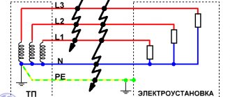
The circuit includes combined neutral and phase conductors .
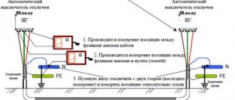
In the event of a short circuit between the phase conductor and the neutral conductor, which is connected to the transformer neutral or housing, a circuit appears called a phase-zero loop. The test is carried out to determine the proportionality of the cutoff current of the machine and the short circuit current . This will clarify the shutdown time of the damaged area and identify the likelihood of such a blackout. They measure indicators on a distant section of the highway in order to use the lowest values of the line.
Current loop resistance depends on factors:
- cable cross-section;
- wire length;
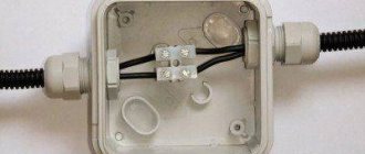
- transition resistance values in junction boxes on the route.
Valera
The voice of the construction guru
Ask a Question
Based on the obtained parameters, the probable short circuit current is calculated and compared with the cutoff current of the protective device. The circuit current decreases as the internal resistance of the circuit increases, so the machine may not work. Timely measurement using a loop will prevent an emergency situation.
Why measure the resistance of the phase-zero loop?
Information about the resistance on the phase-zero loop is obtained after measurements. The information helps to calculate how long it will take for the protective mechanisms against overcurrents (overloads) to operate in the event of a short circuit. That is, the quality of connections in the electrical circuit, the safety of electrical wiring, and the operation of the protective mechanism are checked.
About terms. When a phase wire is shorted to a neutral wire at the point of consumption, a circuit is formed between the phase and neutral wires, which is called a phase-zero loop. It includes: a transformer, switches, switches, starters - all switching equipment.
Measurements are required in the following cases:
- before the start of electrical installations (when putting the building into operation);
- during planned or major repairs;
- during scheduled inspections (for example, at energy, residential or commercial facilities, etc.).
For your information! The response time of protective devices must meet the requirements of clause 1.7.79 of the PUE. The parameter is calculated using special formulas.
The need to measure F-N resistance
The method allows you to compare the actual resistance measured in practice with the projected indicator included in the planning. If the circuit is installed properly, both values will coincide, which means that the operation of the line will be safe.
Purposes of phase-zero loop measurement:
- checking installation quality to find errors and weak areas;
- safety assessment of automatic protection equipment;
- testing of electrical installations upon delivery and acceptance into operation after reconstruction or installation;
- at the request of regulatory organizations, for example, Rostechnadzor;
- at the request of the owner of the main line or electrical units.
Valera
The voice of the construction guru
Ask a Question
The length of the cable line from the transformer to the consumer outlet is measured in hundreds of meters. There are many connectors in the line design that lose voltage even when installed correctly. Internal resistance measurements are carried out to identify negative areas and enhance protection on them.
How often are measurements taken?
The frequency of readings and calculations is carried out in accordance with the preventive maintenance schedule developed by electrical engineers. The document contains recommendations for maintenance and testing of systems, and is signed by the head of the enterprise.
Recommended inspection periods in accordance with GOST R 50.571 – 2007:
- for electrical appliances and installations operating in areas of increased explosion hazard - once every 2 years;
- if automatic protection fails, an immediate unscheduled check is performed;
- mandatory - during acceptance and commissioning, when putting equipment into operation;
- for standard conditions, after successful completion - once every 3 years.
At the request of the owner or the recommendation of the responsible person regarding technical inspection and monitoring of electrical equipment, such measurements are made more often.
home
Protocol+ program for electrical laboratory
The Protocol+ program allows you to significantly reduce and automate the process of activity of electrical laboratory employees associated with filling out test (measurement) reports, eliminate the costs of drawing up single-line electrical diagrams, lists of defects with recommendations for replacing circuit breakers after checking them and preparing title documentation.
Certificate of state registration of the program No. 2010610081. The key difference between the Protocol+ and similar ones is that the program was created by a test engineer and was refined over several years in order to optimize and facilitate the creation of test reports and single-line diagrams.
The cost of the Protocol+ program is 50 thousand rubles.
New version of the Protocol+ 110 program 06/07/2015
(the 2015 version of the program does not mean that development has stopped and the project has been abandoned. This fact only indicates that all errors over the years have been corrected and customer wishes have been taken into account. The author of the program does not artificially change the version of the program without significantly changing the functionality of the program itself .)
The program provides the following functions:
— correct generation of filling out the “Phase-zero” test report with automatic determination of technical characteristics and response time of protection devices for compliance with RD requirements;
— automatic filling and formatting of the “Insulation Resistance” protocol;
— automatic creation of the “Resistance of transition contacts” protocol;
— automatic creation of the RCD check protocol;
— automatic creation of a test protocol for “Circuit Breakers”;
— automatic creation of the “Resistance of grounding devices” protocol;
— automatic creation of a “Visual inspection” protocol;
— automatic creation of a list of defects for the phase-zero protocol with recommendations for elimination;
— automatic creation of a list of defects for the visual inspection protocol;
— automatic creation of title and design documentation for the report as a whole;
— automatic creation of “Single-line diagrams” in DWG format.
System requirements:
— Operating system Windows XP, Vista, 7, 8, 10;
- MS Excel versions 2007 - 2016 (RUS / ENG);
- AutoCAD versions 2006 - 2022 or, not entirely preferably, a FREE domestic analogue of nanoCAD (with limited functionality of the free version) (www.nanocad.ru). (AutoCad and AutoCad LT are different. Diagrams are not drawn in AutoCad LT, because AutoCad developers have disabled interaction with external programs)
Using the program:
The Protocol + program comes with an electronic USB key (details https://www.guardant.ru/products/all/guardant-code/). One key is enough for one organization with any number of workplaces, since the Excel specification is initially filled out, and only then the program creates protocols and draws single-line diagrams based on the completed specification, which takes a few minutes in total. Thus, several operators can simultaneously fill out specifications for different objects, and then alternately create reports using the program.
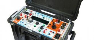
Circuit Resistance Testers
All modern electrical laboratories have meters. The devices reproduce a fake short circuit on a controlled section of the circuit or inside the unit, then immediately measure the resistance of the phase-phase, phase-zero loop (reactive, active, total electrical resistance).
The device instantly calculates the short circuit current without turning off the protection. This is how they check the correctness of the selected nominal value of the machine or fuse. At the same time, they determine the response time of the protection.
Devices help determine:
- values of transition resistances of switching devices (switches, circuit breakers, fuses, contactors, disconnectors, etc.);
- the exact trajectory of the electric current in the event of an accident (through steel pipes, metal water pipes, circuits, other pipelines with iron walls, grounding cable).
The box of devices has holders in the form of magnets, so they can be quickly fixed to steel walls. Paint on metal does not interfere with retention.
What devices are used?
To measure phase parameters, special verified devices are used. The devices differ in measurement methods, as well as design features. The following measuring instruments are most popular among electricians:
- M-417. A device proven by experience and time, designed to measure resistance without disconnecting the power source. Features include ease of use, dimensions and digital display. The device is used in any AC networks with a voltage of 380V and a permissible deviation of 10%. M-417 automatically opens the circuit for an interval of up to 0.3 seconds to take measurements.
- MZC-300. Modern equipment for checking the condition of switching elements. The measurement technique is described in GOST 50571.16-99 and consists of simulating a short circuit. The device operates in networks with a voltage of 180-250V and records the result in 0.3 seconds. For greater operational reliability, low or high voltage indicators are provided, as well as overheating protection.
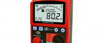
- IFN-200. A microprocessor-controlled device for measuring the resistance of the phase-zero loop without turning off the power. The reliable device guarantees the accuracy of the result with an error of up to 3%. It is used in networks with voltages from 30V to 280V. Additional advantages include measuring short-circuit current, voltage and phase angle. The INF-200 device also remembers the results of the last 35 measurements.
Measurement technique
The verification takes place in two stages:
- external control;
- phase-zero loop measurement.
At the first stage , the power panels are inspected, the correct assembly is checked, and attention is paid to the electrical supply diagram. They determine the current of circuit breakers and fuses, check the external integrity of protective devices, the tightness of the joints of wires with each other and with the circuit breakers.
At the second stage, the contacts of the meter are installed in the corresponding sockets and brought to the contacts of the socket on the other side. The voltage value appears on the display. Press the regulation switching key, the built-in contact closes, and a load resistor with a current of more than 10 A is connected in the circuit. The device measures the electric current, calculates the resistance, and displays it on the screen.
Analysis of results
After the measurement, there is the nominal voltage of the circuit and the impedance value. In the event of a short circuit, a single-phase electric current will flow through the main line.
To determine it, use the formula I = Unom/Rp, where:
- I is the strength of the circuit current;
- Unom - voltage (nominal);
- Rп - total resistance.
There are 2 options :
- the cut-off current is less than in the circuit - the machine will not react, only thermal protection will work with an interval of 0.4 seconds (there is a risk of fire);
- The current of the machine corresponds to the norm , so the switch will operate in a timely manner.
The correct choice of ratings of the automatic protection installed in this line is assessed so that it is possible to prevent an accident. According to the PUE standards, a machine is installed that provides an indicator of 1.1 times the rated fault current with an instantaneous breaker.
Filling out the protocol
Sample protocol
The form is filled out by a representative of the controlling company.
The protocol indicates:
- name and details of the customer;
- purpose of the inspection (passing tests, unscheduled control, etc.);
- environmental conditions during testing (humidity, air temperature);
- test results in the form of a table, where there are corresponding columns for the name of the equipment, measurement area, type of protective device and all obtained indicators;
- information about the measuring instruments used;
- expert's conclusion.
At the end there are signatures of the employee who carried out the control and the head of the laboratory. Based on the results of the study, the machines are replaced and the network is repaired (if indicated). After this work, new control measurements are organized.
What information should be in this protocol?
The protocol form is drawn up by the executing company. You can use the information presented below as a basis.
So, what should be indicated in the protocol:
- Name of the company conducting the equipment inspection, address, certificate of registration and other data.
- The name of the document, its number and date of preparation.
- Customer of measurement data.
- The purpose of the measurements: acceptance tests, routine inspection of equipment, inspection after replacement of equipment.
- Environmental conditions during measurements: temperature, humidity. The environment has a great influence on the quality of a cable or overhead line.
- Test results. They are presented in the form of a table. The columns in it can be as follows: number in order; Name of equipment; measurement location - protection installation location; data on protection methods (fuse, thermal release, electromagnetic release, etc.); measured circuit resistance; circuit resistance without connecting wires; rated current; does the voltage meet the standards? response time of the protective mechanism.
- What measuring instruments were used for measurements, their error, date of verification.
- Expert opinion.
At the end of the document, the employee who conducted the tests and the head of the electrical laboratory sign.
If the measurement results are unsatisfactory, then it is necessary to carry out repair work on the electrical network, and then organize a new test.
Safety precautions
Tests are allowed to be carried out by workers over 18 years of age who have received all types of safety training. When taking measurements, the team must have 2 people, one of whom has an ES clearance group of at least III.
Safety regulations:
- the work site is fenced;
- work in rubber shoes or stand on a dielectric mat;
- wear rubber gloves; short or rolled up sleeves of overalls are not allowed;
- the handles of the tool must be insulated;
- cannot be measured at air temperatures below +5°C.
After work, they disassemble the measuring circuit, collect the wires, hand over the inspection site to the permitting person, and report to the authorities about the identified malfunctions.
Measurement procedure using MZC-300
Before proceeding directly to the tests, we will briefly describe the adopted procedure, it includes:
- Compliance with certain conditions that ensure the necessary accuracy.
- Selecting a device connection method.
- Obtaining information about the network voltage.
- Measuring the main characteristics of the F-N loop.
- Reading the received information.
Let's look at each of the stages listed above.
Compliance with certain conditions
Some features of the meter should be taken into account:
- The device will not allow testing if the rated network voltage exceeds the maximum value (250V). Exceeding the measurement range (250.0 V) will result in an “OFL” warning being displayed on the device screen, accompanied by a long sound of the buzzer. In this case, the device should be turned off and disconnected from the loop being measured.
- If the neutral or protective conductors are broken, an error in the form of the “—” symbol will be displayed on the device screen, accompanied by a long buzzer signal.
- The voltage level in the loop being measured is insufficient for testing, usually if it is below 180.0 volts. In this case, the screen will display an error with the symbol “U”, accompanied by two beeps.
- Thermal blocking of the device is triggered. In this case, the “T” symbol is displayed on the screen, and the buzzer gives two long beeps.
Selecting a device connection method
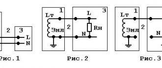
Let's consider several options for electrical connection diagrams of the device for testing:
- Removing characteristics from the “F-N” loop; in the example shown in the figure, the parameters in the C-N circuit are measured.
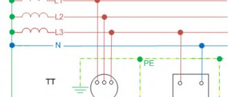
C-N loop test - Measurement in a loop between one of the phases and the PE conductor.
C-PE loop test - Measurements in CT circuits.
Connecting the device in circuits with protective grounding
- To check the reliability of grounding of electrical equipment, the connection method given below is used.
Testing the reliability of grounding of electrical equipment enclosures
Obtaining information about the network voltage
The device we are considering allows you to measure UH within the range from 0 to 250.0 volts. The phase voltage is displayed on the device display immediately after pressing the power button or after five seconds, after testing (if the control buttons responsible for displaying the results on the screen were not pressed).
Measuring the main characteristics of the F-N loop
The method for measuring ZP in a loop, used in the MZC model range, is based on creating an artificial short circuit using a limiting resistance (10.0 Ohm), which reduces the value of the ISC. After testing, the microprocessor of the device calculates ZP, highlighting reactive and active components. The measurement procedure does not exceed 30.0 ms.
It is characteristic that the device automatically selects the desired range for measuring ZP. When you press the “Z/I” button, the display alternately displays such basic characteristics of the loop as expected short-circuit current (ISC) and total resistance (ZP).
It should be taken into account that when calculating, the microprocessor sets the UH value at 220.0 volts, while the current rated voltage may differ from the calculated one. Therefore, to increase the accuracy of electrical circuit measurements, a correction should be made. For example, with a real UH equal to 240.0 V, the correction to reduce the instrument error will be equal to 1.09 (that is, it is necessary to divide 240 by 220).
The process of measuring loop characteristics is started by the “Start” button.
Reading received information
As mentioned above, tests begin after pressing the “Start” button. After completing the measurements, the characteristics of the “F-N” loop are displayed on the screen, depending on the settings. You can scroll through the information displayed on the display using the “SEL” and “Z/I” buttons.
Please note that the MZC-300 only displays the results of the last measurement. If it is necessary to store the results of all tests in electronic memory, you will need a device with advanced capabilities, for example the MZC-303E device.
MZC-303E device for measuring the characteristics of the F-N loop
Such a device allows you not only to store information about all measurements in electronic memory, but also, if necessary, transfer it to a computer using a USB interface.
The need for measurements
Loop resistance is measured in the following cases:
- During commissioning, after repair, modernization or re-equipment of installations.
- Requirement from various control services, for example Oblenergo, Rostechnadzor, etc.
- According to the consumer.
During electrical measurements, certain parameters of the F-N loop are established, namely:
Total circuit resistance, which includes:
electrical resistance of the transformer at the substation;
similar parameter of the linear conductor and working zero;
Numerous transient resistances formed in switching equipment, for example in protective devices (AV, RCD, differential circuit breakers), starters, manual switches, etc. Also influenced by the cross-section of conductors, cable insulation, grounding of the transformer neutral, parameters of the RCD or other protection of electrical installations.
Short circuit current (ISC). In principle, it can be calculated using the formula: ISC = UН / ZП, where UН is the nominal voltage level in the electrical network, and ZP is the total loop resistance. Considering that protective devices during a short circuit must automatically turn off the power according to established temporary standards, the following condition must be met: ZП*IAB
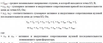
Before describing detailed measurement techniques, it is necessary to briefly describe the instrument that will be used in the process - the MZC-300. We chose this device because it is most often used by measurement laboratories.