Application area
The recommendations of this method are used when checking and testing circuit breakers, overload protection devices for electric motors (thermal and other types of relays), various starters and simple relays, as well as load switches for voltages up to 1 kV.
Devices used to turn on and off the main circuits in systems that generate electrical energy and transmit it to consumers are energy distribution switching devices. They turn the circuit on or off when operated by maintenance personnel or automatically.
Power distribution switching devices perform two functions:
• Non-automatic switching on and off of electrical circuits that occur when it is necessary to supply or remove power from a network section
• Automatic shutdown of electrical circuits in the event of any phenomena appearing in them that threaten the safety of operating personnel or the safety of the installation (for example, in the event of short circuits). Sometimes devices automatically turn on a backup power source or automatically turn on again after an emergency shutdown.
The following groups of switching devices are distinguished:
• Automatic switches (automatic machines)
• Fuses (fuses)
• Non-automatic switches
Sometimes these devices are installed together with control equipment in devices for controlling electric drives (control stations, magnetic starters, etc.).
Contactors, starters, rheostats, relays that protect and control the operation of an electric drive are called control devices.
Abnormal modes are those in which there is an excessive decrease in voltage, and, in particular, the flow of overcurrent (current greater than the rated one).
An extreme drop in voltage can cause the motor to stop and then, when full voltage is suddenly restored, to start at the wrong time. Therefore, sometimes automatic switches are used on critical branches to the receiver, turning off the circuit when the voltage drops to 35-70% of the rated voltage. Restarting must be done under operator intervention.
The most dangerous and frequently occurring abnormal mode is the flow of overcurrent during a short circuit or excessive current consumption by electrical energy receivers. The shutdown equipment must reliably switch all currents, up to the highest short-circuit current that may occur at the place of its installation. Non-automatic switches at these currents should not be damaged and switch off spontaneously.
Control equipment (contactors, starters) is designed mainly for switching currents not exceeding the overload current of electric motors (no more than 10 times the rated value). The control equipment for individual electrical receivers is protected from short-circuit currents using energy distribution equipment.
For uninterrupted operation of the installation, it is necessary to ensure selectivity (selectivity) of shutdown of control equipment and power distribution equipment, as well as selectivity of shutdown of several devices connected in series. This means that when overload currents arise in a branch to a separate receiver, the corresponding section of the circuit must be turned off by the control equipment of this receiver, and not by the switchgear equipment installed on the branch. If a short circuit occurs on a branch, the power distribution device must be switched off, not the control device.
Selectivity is especially important in a power distribution system. For all overcurrent values, up to the maximum short circuit current, only one device located closer to the accident site should be turned off; all other devices with a higher rated current located closer to the energy source should not be turned off.
It would be desirable to have such a protective characteristic that in the entire range of overcurrents there is a time delay inversely dependent on the current (the higher the current, the shorter the shutdown time), since the destructive effect is greater, the higher the current and the duration of its action. For design reasons, devices are often used that, at currents greater than a certain value, operate instantly (without a deliberately created time delay). For the same reasons, devices that have a time delay independent of the current are sometimes used.
After turning off the device during overcurrents, it is advisable to turn it on as soon as possible. For this purpose, switches are used, except automatic ones with thermal control elements, which allow immediate activation after operation. Automatic switches with thermal elements must allow restarting no later than 1-3 minutes after shutdown during overcurrents. If the circuit breaker trips without overload, it must be capable of immediate reclosure.
Switch testing devices
The complexes used to test switches are specially designed for this purpose. An exception is the RETOM series devices, which are originally intended for testing relay protection, but can also be used to supply currents to the contact system of the circuit breaker with control of the moment of shutdown.
RETOM-21 is most suitable for this purpose. Testing the operation of the thermal release is carried out by applying a continuous current simultaneously with starting the device’s stopwatch, configured to record the disappearance of the current during shutdown. Electromagnetic releases are tested by currents supplied by pulses of duration set by the user. With a gradual increase in current, the overload protection of the machine will inevitably trip.
An important advantage of RETOM is that the current supplied for testing is sinusoidal. Most other devices specially designed for testing machines produce a pulse current generated by thyristor regulators
But their dimensions are smaller and management is simpler.
There are many such devices. To check the cutoff, they also supply current with increasing amplitude pulses of adjustable duration, and to check thermal protection, the required current is set and the stopwatch is started.
Test object
Automatic switches (automatic circuit breakers) are designed for infrequent opening and closing of an electrical circuit and long-term passage of current through it, as well as for automatic opening of circuits when various abnormal conditions appear in them; circuit switching occurs between mechanically moving contacts.
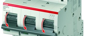
Automatic machines are divided into slow-acting and high-speed. High-speed ones are characterized by their own response time, that is, the time from the appearance of the short circuit current until the contacts begin to diverge.
Low-speed machines include machines that usually do not have special performance requirements or these requirements are low. To hold the contact system in the on position, latches are used. These machines have their own response time from 10 to 100 ms and do not have a current-limiting effect.
Based on their design, they distinguish between machines with a plastic cover and body (for currents up to 630A inclusive) and machines without a case and cover (for currents from 630 to 1000A inclusive).
High-speed circuit breakers, manufactured for rated direct currents of 1500-15000A, have their own shutdown time at high currents of no more than 5 ms. Their characteristic feature is that the entire design is subject to the requirement of increasing performance.
Figure 1 shows an AR series circuit breaker in a withdrawable version. To extinguish the arc, spark arresting chambers are installed above the switch contacts (Figure 2). Both machine buses (1) at the output ends are equipped with vertical connecting flags (4,5), which allow direct fastening of the retractable contacts. The circuit of arcing contacts is formed by two movable arcing contacts (3), which are connected to the circuit of the main contacts by means of flexible copper belts. Instant shutdown is ensured by a spring accumulator (8) through a lever transmission and a release mechanism (7). The machine is turned on either using a button on the front panel or using a switching electromagnet (17). Switching off is also carried out using the red button u1082, or using an electromagnet (18). The battery is tensioned automatically, after turning on the machine, by the drive (10). This operation can be performed manually using a lever transmission (9).
BA series circuit breakers can be manufactured in various modifications. To do this, additional parts are installed on the machine, which ensure its withdrawable version (Figure 3, lower part), stationary version (Figure 3, middle) or stationary version with manual execution (Figure 3, upper part).
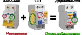
Types of circuit breakers
The most recognizable to users is the household series of modular circuit breakers. They are mounted on a DIN rail and have no adjustable response characteristics. All settings of releases for a modular series of circuit breakers and differential circuit breakers are calculated from their rated current.
Modular circuit breaker
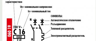
The cut-off current depends on the letter designation preceding the rated current value.
| Letter designation | Cut-off current ratio |
| IN | 2-5 from IN |
| WITH | 5-10 from IN |
| D | 10-20 from Inom |
This means that the actual value of the current at which the machine will operate lies in a certain range. The manufacturer guarantees that this will be so.
Thermal releases of modular series machines begin to operate when the rated current is exceeded. The time after which the shutdown occurs depends on the ratio of the overload current passing through the machine to the rated one. Circuit breakers from different manufacturers have different tripping times. It can be determined by the characteristics that are determined from the reference data for this series of machines. But this value also has a scatter, so the shutdown characteristic is not one curved line, but a family of them, indicated by a shaded area. For a certain current through the circuit breaker, the expected response time lies in the range determined at the boundaries of this zone.
Time-current characteristics of modular switches
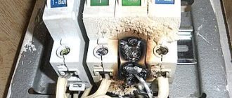
Until now, in distribution panels there are machines that have either only thermal or maximum protection. Checking these devices is most important, since their electromechanical part has served for many years, some of the parts are rusty and inoperable.
Outdated switch models
The next type of circuit breaker has an unregulated cut-off and adjustable thermal protection. To do this, there is a regulator on its front panel, with the help of which the rated current of the thermal release changes within 0.5 - 1.0 of the rated current of the machine. Such machines are used to protect electric motors and fine-tune the current of the protected cable line, ensuring selectivity of overload protection. The regulator sets the current at which the thermal protection begins to operate. The position of the regulator is also reflected in the family of characteristics of the switch.
Automatic with adjustable thermal protection
The design of the switch is even more complex; in addition to an adjustable thermal release, it also has an adjustable electromagnetic release. There are models in which the adjustment is carried out mechanically: by changing the force of the spring, which counteracts the force created by the trip coil. Such devices are found on old-style switches.
In modern automatic machines, adjustments are made using a built-in protection unit. This is a complex that includes current sensors installed on all three phases of the switch, and a semiconductor device that processes the received signals.
Circuit breaker with semiconductor release
The composition of the protections installed in the maximum configuration in such machines:
- maximum current cut-off with adjustable current-independent time delay;
- overload protection with adjustable starting current and time response characteristic;
- protection against single-phase fault currents, with an adjustable setting and time delay.
Determined characteristics
Visual inspection.
An external inspection determines the condition of accessible parts of circuit breakers and control devices for visible damage, the presence of chips in insulating materials, the absence of fastening parts, etc.
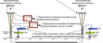
Insulation resistance measurement.
The insulation resistance is measured between each wire (pole) of the device and the ground, as well as between every two wires (poles). The insulation resistance must be at least 1 MOhm.
When measuring the insulation resistance of circuit breakers together with the cables and wires connected to them, the insulation resistance must be at least 0.5 MΩ.
High voltage test.
The test is carried out during commissioning, major repairs, and also in case of unsatisfactory results of insulation measurements.
The test voltage value is 1 kV 50 Hz. test duration is 1 minute. During routine repairs, instead of testing with alternating voltage, it is allowed to carry out a one-minute insulation measurement with a megger at a voltage of 2500V.
Checking the operation of maximum, minimum or independent releases of automatic machines and control devices.
The operation of the releases must comply with the factory data and the requirements for ensuring protective characteristics.
Checking the operation of contactors and circuit breakers at reduced operating voltage.
The operating voltage value and the number of operations are given in Table 1.
| Operation | Operating voltage | Number of operations |
| Inclusion | 0.9Unom | 5 |
| Shutdown | 0.8Unom | 5 |
Checking fuses.
The fuse link must be calibrated.
Test and measurement conditions
Testing of automatic machines and control devices is carried out at an ambient temperature not lower than +100C.
Checking the maximum releases of automatic machines and starters should be carried out taking into account the introduction of temperature corrections since the temperature of the maximum releases made on the basis of bimetal has a significant impact on the time characteristics of the machines. Current corrections for temperature are shown in Table 2.
Ambient air humidity is important when conducting high-voltage tests, because... Condensation on the insulating parts of devices can lead to breakdown of insulation and, accordingly, to failure of the equipment (both testing and under test). Before carrying out high-voltage tests, the devices should be wiped free of dust, dirt and moisture.
Atmospheric pressure does not have a special impact on the quality of the tests.
Measuring instruments
Automatic machines and control devices are tested in assembled form, with all parts and assemblies installed on them that may affect the test result.
Before testing, an external inspection is carried out, checking the integrity of the housings and insulation. Insulation resistance is measured using megohmmeters for voltages of 1000V and 2500V.
Measuring the resistance of contacts and contact connections inside devices is carried out using direct current bridges (for example P 333), which allow measurements to be made with an accuracy of 0.001 Ohm, or by the ammeter and millivoltmeter method. When carrying out measurements using the ammeter-voltmeter method, the operating current should not exceed the rated current of this device.
Testing with increased power frequency voltage is carried out using various installations, which consist of the following elements: test transformer, control device, instrumentation and protective equipment. Such devices include the installation AII - 70, AID - 70, as well as various high-voltage test transformers, which have a sufficient level of protection and are adequately prepared for testing. To control the quality of bolted connections, plumbing tools in the form of wrenches, etc. are used.
Checking the IEK circuit breaker for authenticity
Weight of IEK machine;
- IEK VA 47-29 - 87 gr.
- IEK VA 47-29M weight 97 g.
- IEK VA 47-60 weight 105 g.
For comparison: A pack of cigarettes weighs 22-23 grams. A thin smartphone is 130-140 grams, a “thick” smartphone weighs 170-180 grams.
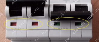
IEK marking is required in Latin IEK;
Old marking of IEK protection circuit breakers
The color of the stripe under the IEK logo must exactly match the color of the cocking lever;
New, correct marking of IEK circuit breaker
There is a high probability that the IEC machine is counterfeit
Information about the machine and the address of the manufacturer’s website must be stamped on the case;
The inscriptions and diagram of the machine must be clearly visible on the front of the case.
conclusions
Unfortunately, the findings are disappointing. It is impossible to visually check the serviceability of a circuit breaker when purchasing it 100%. But this does not mean that this should not be done. Be sure to buy automatic electrical circuit devices in specialized stores, exclude hardware stores and hypermarkets. When purchasing, carry out a visual inspection of the machine and, based on the obvious signs described in this article, check the machine for authenticity.
No entries found
Procedure for testing and measurements
Visual inspection.
External inspection of automatic machines and control devices is carried out by opening the housing. All internal connections and parts of the switch, the operation of the on and off mechanism, the condition of insulating parts, coils and block contacts are inspected.
| Ambient temperature | Circuit breaker current | ||||||||||
| 16 | 20 | 25 | 32 | 40 | 50 | 63 | 80 | 100 | 125 | 160 | |
| 10 | 54 | 67 | 84 | 110 | 141 | 175 | 212 | 269 | 339 | 424 | 538 |
| 12 | 53 | 67 | 83 | 109 | 139 | 174 | 210 | 267 | 337 | 421 | 534 |
| 14 | 53 | 66 | 83 | 108 | 138 | 172 | 209 | 265 | 334 | 418 | 530 |
| 16 | 53 | 66 | 82 | 107 | 137 | 171 | 207 | 263 | 332 | 415 | 527 |
| 18 | 52 | 65 | 82 | 106 | 135 | 169 | 206 | 261 | 329 | 411 | 523 |
| 20 | 52 | 65 | 81 | 105 | 134 | 167 | 204 | 259 | 327 | 408 | 519 |
| 22 | 51 | 64 | 80 | 104 | 132 | 166 | 203 | 257 | 324 | 405 | 515 |
| 24 | 51 | 64 | 80 | 103 | 131 | 164 | 201 | 255 | 321 | 402 | 511 |
| 26 | 51 | 63 | 79 | 103 | 130 | 162 | 199 | 253 | 319 | 398 | 507 |
| 28 | 50 | 63 | 78 | 102 | 128 | 160 | 198 | 252 | 316 | 395 | 504 |
| 30 | 50 | 62 | 78 | 100 | 127 | 159 | 196 | 250 | 313 | 392 | 500 |
| 32 | 49 | 62 | 77 | 100 | 124 | 157 | 195 | 248 | 311 | 388 | 495 |
| 34 | 49 | 61 | 76 | 99 | 123 | 155 | 193 | 246 | 308 | 385 | 492 |
| 36 | 48 | 61 | 76 | 98 | 121 | 153 | 192 | 244 | 305 | 381 | 488 |
| 38 | 48 | 60 | 75 | 97 | 120 | 151 | 190 | 242 | 302 | 378 | 483 |
| 40 | 48 | 60 | 75 | 96 | 120 | 150 | 189 | 240 | 300 | 375 | 480 |
| Ambient temperature | Circuit breaker current | ||||||||||
| A3720 | A 3730 and A3740 | ||||||||||
| 160 | 200 | 250 | 250 | 320 | 400 | 500 | 630 | ||||
| 10 | 536 | 679 | 849 | 856 | 1106 | 1376 | 1698 | 2141 | |||
| 12 | 532 | 675 | 843 | 849 | 1097 | 1366 | 1686 | 2124 | |||
| 14 | 529 | 669 | 837 | 843 | 1087 | 1355 | 1674 | 2109 | |||
| 16 | 525 | 664 | 831 | 836 | 1078 | 1344 | 1658 | 2089 | |||
| 18 | 521 | 659 | 824 | 829 | 1068 | 1332 | 1647 | 2075 | |||
| 20 | 518 | 654 | 818 | 822 | 1058 | 1320 | 1631 | 2055 | |||
| 22 | 514 | 649 | 811 | 815 | 1050 | 1308 | 1619 | 2039 | |||
| 24 | 510 | 643 | 804 | 807 | 1039 | 1296 | 1604 | 2019 | |||
| 26 | 506 | 638 | 798 | 800 | 1030 | 1286 | 1592 | 2005 | |||
| 28 | 503 | 633 | 791 | 793 | 1020 | 1274 | 1582 | 1994 | |||
| 30 | 499 | 627 | 784 | 787 | 1011 | 1261 | 1561 | 1571 | |||
| 32 | 495 | 622 | 777 | 780 | 1000 | 1248 | 1556 | 1960 | |||
| 34 | 491 | 616 | 770 | 772 | 991 | 1246 | 1541 | 1943 | |||
| 36 | 487 | 610 | 763 | 765 | 980 | 1224 | 1527 | 1920 | |||
| 38 | 483 | 605 | 756 | 757 | 970 | 1212 | 1515 | 1909 | |||
| 40 | 480 | 600 | 750 | 750 | 960 | 1200 | 1500 | 1890 | |||
Insulation resistance measurement.
Insulation resistance is measured with fully assembled devices, as well as with the device secured to the base. The measurement is made between every two phases and between each phase and ground separately. If the device has on and off coils, then the insulation resistance is measured between them and the phases of the device and between the coils and the ground separately. Fully insulated units must first be installed on a metal base. Schemes for measuring insulation resistance are shown in Figure 4; a circuit breaker is taken as an example.
High voltage insulation test.
The test is carried out in phases with grounding of the phases free from testing and in fully assembled devices with the installation of all parts that may affect the test result.
The scheme according to which the test is carried out is presented in Figure 5.
If the device under test is installed on a metal base, then during testing it must also be grounded.
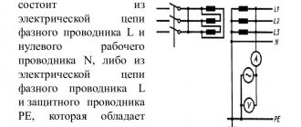
Checking the operation of maximum, minimum and independent releases.
The operation of the releases is checked in accordance with the diagram in Figure 6. To record the operation time of the device, electric stopwatches are used, which are connected to the free phases of the circuit breaker or to the block contacts of control devices.
The maximum releases of automatic circuit breakers are checked using three times the current of the release (if there are no other instructions in the machine’s passport) adjusted for temperature (see above). The releases of circuit breakers with semiconductor protection units are tested with the current of the protection unit (usually six times). The time characteristics of various machines are given in the appendix to this technique. The check is carried out from the “cold” state of the machine. Having checked one phase, you can immediately make switches and begin checking the next one.
Checking the response time of thermal motor protection relays is carried out in accordance with the diagram in Figure 6 (as for an automatic machine), except that the stopwatch is switched on to the block contact of the relay. The current for testing is selected based on the passport data: if there are time-current characteristics for a specific relay, the loading current is equal to three times the relay current (testing from a cold state). After checking with a triple current and cooling of the thermal element, a current equal to 1.2 In is supplied to the relay, and the relay should turn off within a time of 20 minutes.
Checking the electromagnetic releases of automatic circuit breakers and cut-off releases for switches with semiconductor protection units is carried out according to the scheme in Figure 6, while first setting the current equal to 0.8Irast and checking the stable non-operation of the circuit breaker, and then setting the current equal to 1.1Irast, checking the operation of the switch for a certain time timed by a stopwatch. The amount of time when checking electromagnetic releases and semiconductor cut-off protection is very small!
Based on the results obtained, an individual characteristic of this circuit breaker (protection relay) is constructed.
Checking the operation of contactors and circuit breakers at reduced operating voltage.
The check is carried out according to the diagrams in Figure 6. Accordingly, the operating current is changed to check whether it is turned on or off.