Documentation
General provisions.
This technique is intended to measure the response time of protection devices with thermal, electromagnetic and semiconductor releases in order to verify compliance with the requirements of paragraph 413 of GOST R50571.3-94, which ensures the safety of indirect contact with non-current-carrying metal parts of the equipment at the moment of short circuit of the phase conductor.
The disconnection time for distribution circuits should not exceed 5 s if the protective earth resistance is less than:
where Uo is the rated phase voltage, Zo is the phase-zero circuit resistance, i.e. low enough to provide a safe touch voltage on metal parts of the equipment, and 0.4 s for circuits supplying mobile and portable equipment and for distribution circuits in which the above condition for protective earth resistance is not met.
The object of measurements are automatic circuit breakers, which serve to protect AC distribution networks and power receivers in emergency cases when the insulation is damaged. To carry out protective functions, circuit breakers have maximum releases against overload currents and short circuit currents. When currents passing through the circuit breaker exceed the rated current of at least 20%, the latter must be turned off. Overload protection is provided by thermal or electronic devices. Protection against short circuit currents is carried out by electromagnetic or electronic releases.
The measured quantity is the disconnection time of the breaker at a given current value exceeding the rated value of the breaker current.
2.
Scope and standards of testing
According to the PUE 7th ed. clause 1.8.37, PTEEP 2003 (Appendix 1 §26) and Rules for the maintenance of relay protection and electrical devices. networks 0.4 - 35 kV (RD 34.35.613-89 §58) Electrical devices up to 1 kV are tested during commissioning, as well as during its operation in the following volume:
2.1.
Insulation resistance measurement
The insulation resistance of the devices must correspond to the values indicated in the table. 1.8.37 PUE and table 37 PTEEP, but not less than 0.5 MOhm. The frequency of inspection during commissioning and during commissioning is at least once every 6 years.
2.2.
Test voltage for circuit breakers, magnetic starters and contactors is 1 kV. The duration of application of the normalized test voltage is 1 min.
The test voltage of 1000 V industrial frequency can be replaced by measuring the one-minute insulation resistance value with a megohmmeter at a voltage of 2500 V. In this case, measuring the insulation resistance with a 500 - 1000 V megaohmmeter according to clause 1.1 can be omitted (see clause 28.3, appendix 3 of PTEEP; clause 1.8.37 of the PUE).
2.3.
Checking the operation of maximum, minimum or independent releases of automatic circuit breakers (AB).
Checking the operation (operability) of maximum (thermal, electromagnetic and combined) AV releases, thermal releases of magnetic starters (PM) is carried out with a primary current from an external current source both when putting electrical installations (or a separate AV or PM device) into operation, and during their operation within the time limits determined by the maintenance schedule for electrical equipment of the enterprise.
Fuse links must be checked at the same time as other protective devices. At the same time, their compliance with the nominal parameters of the protected equipment, the absence of cracks in the fuse housings, and the presence of filler are checked.
2.4.
Checking the operation of circuit breakers and contactors at reduced and rated operating current voltages.
Voltage values and number of operations when testing circuit breakers and contactors by repeated switching on and off
are given in table. 18.40 PUE.
During preventive tests, this check is carried out at least once every 12 years (clause 28.8 appendix 2 of PTEEP), except for the cases specified above for explosive areas.
3. Test conditions.
When conducting tests, the following conditions are observed:
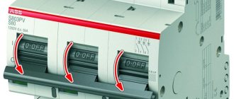
The switch is installed vertically.
Switches intended to be installed in a separate enclosure are tested in the smallest enclosure specified by the manufacturer.
Tests are carried out at a frequency of (50 ± 5) Hz.
During testing, maintenance or disassembly of the vehicle is not allowed.
Tests are carried out under artificial or natural light, at a temperature of 20-25 0C and relative humidity up to 80% (at 25 0C), and are protected from excessive external heating or cooling.
4.
Test method.
Tests of automatic circuit breakers are carried out in accordance with the requirements of GOST R 50345-92 (clause by checking the time - current characteristics. Standard ranges of instantaneous tripping currents in accordance with GOST R 50345-92 clause 4.3.5 are shown in Table 1.
Instantaneous tripping current ranges. Table 1.
Requirements for AV
Before choosing a circuit breaker for your own apartment, you should familiarize yourself with the basic requirements for these devices. There are several GOSTs that define such requirements. The main governing documents include: GOST R 50345-99, GOST R IEC 60898-2-2006, GOST R 50030.2-99.
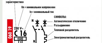
The marking of circuit breakers applied to the body of each product contains information about its main technical characteristics.
The main indicators that all types of machines must meet, according to GOST requirements, are:
- The ability of a device's current-carrying circuit to pass a rated current through itself for an unlimited time. This requirement applies equally to small 6A circuit breakers that provide protection for lighting circuits, and to more powerful devices with a rated current of 63 or 40A, which can be installed on the input electrical panel.
- The ability of a circuit breaker to disconnect a circuit without reducing its performance when short circuit currents occur in it.
- The type of time-current characteristic of the circuit breaker, which must meet the needs of the consumers connected to it.
- Possibility of self-diagnosis of the shutdown mechanism provided by the electronic protection unit.
- Small overall dimensions and weight of the device. This parameter is extremely important when installing the product in small junction boxes or electrical panels.
- Low heat generation during the passage of rated currents, as well as short-circuit currents. This parameter is important from the point of view of ensuring fire safety.
- Short circuit shutdown time when short circuit currents occur.
- Selectivity of protection. Not all types of switches have this quality (as a rule, selectivity of protection can be provided by circuit breakers with a rated current of 40A, as well as 63, 80, 100A and higher). Selective circuit breakers have an additional current path equipped with its own contacts. This additional circuit allows it to respond to changes in the electrical network design that occur as a result of the operation of downstream, less powerful switches. Using this principle allows you to turn off only those sections of the wiring in which an emergency situation has occurred.
- Electrical safety for users.
To check whether the device parameters comply with GOST requirements, the circuit breakers are loaded. For this purpose, special equipment is used to obtain experimental data on such characteristics as rated current, disconnection time of the main contacts, as well as the protection operation current. Loading circuit breakers is not a one-time procedure; the frequency of its execution is determined by the manufacturer.
Checking circuit breakers
Subscribe to the newsletter
According to clause 3.1.8 of the PUE 7th ed. (hereinafter - PUE), electrical networks must be protected from short circuit currents (hereinafter - short circuit) in the shortest possible time. Such protection is carried out by means of fuses or circuit breakers. The main task of a circuit breaker is to break the circuit during emergency conditions. Working in stressful modes has a detrimental effect on the structural elements of the device, therefore, circuit breakers (hereinafter referred to as CB) are subject to periodic maintenance (hereinafter referred to as maintenance) and testing for long-term correct operation.
Features of selection and installation
When choosing a circuit breaker, you should first pay attention to the following characteristics.
Rated voltage
Depends on the voltage of the electrical network (220 or 380 V).
Rated current
An extremely important parameter, which is determined by the total power of all devices connected through the machine. In order to calculate the required rated current, you need to divide the total power of consumers by the voltage of the electrical network. After this, you should select the nearest higher value of the rated current from the standard range defined by GOST.
Important! It is not recommended to install circuit breakers whose rated current significantly exceeds the total network current, since such a solution will significantly reduce the level of electrical safety of the system.
Maximum short circuit current
According to GOST, this parameter characterizes the maximum switching capacity of the switch. The value of the maximum current is applied to the device body in the form of a number showing what maximum current in amperes or kiloamperes is capable of turning off such a machine. The required breaking capacity of the circuit breaker is determined by carrying out fairly complex mathematical calculations or measuring the resistance of the phase-zero loop. In practice, such actions are rarely resorted to; much more often they use an approximate classification of circuit breakers according to the maximum short-circuit current:
- 4500 A. This type of device is suitable for installation in private apartments or houses (ABB SH201L). In most cases, the maximum short circuit current in such electrical networks does not exceed 1000 A.
- 6000 A. (For example, ABB SH200). Switches of this type are used to connect powerful consumers.
- 10000 A and above. Such devices include powerful three-phase circuit breakers (ABB T7 series). Such devices are used in most cases for use as input switches. In this case, there is a certain risk of a short circuit in the immediate vicinity of the input electrical panel. This situation can cause the appearance of large short-circuit currents.
Selectivity of the protection system
Selectivity of the system means its selectivity, that is, the ability to automatically turn off only damaged elements in which abnormal operating conditions occur. To ensure this quality, circuit breakers that have a small rated current (3A or 6A) and are located closer to the load according to the power supply circuit must have a shorter response time than that of input switches (the rated current of which is 40A - 100A).
Loading machines
Loading machines: methods, protocols and frequency
Electrical installation work at any facility must end with acceptance tests and measurements, which are carried out according to the methods specified in the regulatory and technical documentation (PTEEP and PUE). One of their types is loading of machines, which allows you to check the compliance of the parameters of the switches with the nominal data. Monitoring the state of protective automation, the electrical installation of which is carried out according to the project, helps prevent the threat of short circuits (short circuits).
General information
When loading, first of all, the following physical quantities are checked:
- rated current values permissible for normal operating conditions;
- tripping currents of protective automatics - the maximum value to which the circuit breaker reacts in an emergency (during a short circuit or overload);
- system operation periods - the time it takes for the machines to turn off the circuit.
Determining these parameters and comparing them with standard values is the main task of testing switches by an electrical laboratory. If the results do not coincide with the design data, the network must be modified (with the replacement of machines) and reloaded.
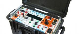
Equipment diagram for testing
The testing process using primary current requires the use of special loading devices. A large number of options for such equipment allows you to select it for any conditions and take into account the cost of testing.
One of the standard verification schemes consists of the following elements:
- control key;
- three transformers: LATR, NT and TT;
- ammeter;
- stopwatch;
- wiring that provides connection of machines with regulated current terminals.
The use of such equipment leads to the induction of a current of up to 50A in the secondary winding of the LT.
A similar scheme is used to load powerful circuit breakers. Although in such a situation the use of more efficient transformer equipment and power supplies is required.
Performing loading
As an example of loading, you can consider checking the BA47-29 circuit breaker. The device has a rated current of 6A and a protective characteristic of “C”. The model is equipped with two types of protection - instantaneous electromagnetic and thermal, in which a certain time is maintained before shutting down.
Both are subject to testing, and before starting it, you should find a graph of the response time depending on the current strength.
Working with a schedule and process features
Using the graph compiled for each machine, you can determine any parameter of its operation:
- Using the X-axis you can see the multiplicity (the ratio of loading currents to standard values).
- The Y axis shows how long it will take for the device to operate.
- To determine the zone in which electromagnetic protection will operate, you should find a range of multiplicity from 5 to 10. In the example, this means the machine is triggered at a current of 30 to 60 A for 0.01–0.02 s.
- Electromagnetic protection is tested with a current of 8 (48 amperes), and the circuit breaker must operate in 0.01 s - this is the yellow line on the graph.
- Thermal protection is triggered in an area limited by two curves that show the hot and cold state of the machine. It is tested with a current of 3 (18A), and the machine turns off within 3–80 s - this is graphically shown by the red line.
You can simplify the connection by using extended stud pins installed on the switch. The connecting wiring is connected to them and loading is performed.
Classification
In order to choose the right input single-pole AV for use in the electrical wiring of an apartment, you should take into account such parameters as rated and maximum currents, response time, overall dimensions, as well as the price of the device and the reputation of its manufacturer. The main characteristics are reflected on the device body in the form of a corresponding designation.
Depending on the response time, the following types of circuit breakers are distinguished:
- Fast-acting. As a rule, DC switches have these characteristics (operation time less than 0.008 s). The requirements for these devices are described in GOST 2585-81.
- Normal speed (0.02 – 0.005 s).
- Reduced performance (response time greater than 0.02 s).
- Selective circuit breaker.
Based on the number of independent electrical lines disconnected by one release mechanism, the circuit breakers can be divided into one-, two-, three- and four-pole. The three-pole circuit breaker is widely used in low-voltage three-phase networks. To organize reliable protection of single-phase networks, as well as DC circuits, a two-pole switch can be used.
Depending on the purpose, the circuit breaker may have a different rated current value and type of time-current characteristic. Currently, GOST establishes the following current ratings of circuit breakers:
- Up to 25 A. Such switches are used to protect household electrical wiring. 3A and 6A devices are used mainly to protect lighting circuits. Circuit breakers with 6A, 10A or 16A can be used for separate connection of more powerful consumers.
- Automatic machines with 32A, 40A and 50A are used as input devices.
- Switches with a rated current above 63 A (100A, 160A) are three-pole devices designed for installation in three-phase networks.
The type of time-current characteristic is indicated on the product body in the form of a letter designation and shows for what type of load this type of machine is suitable.
Type B. This type has the characteristics of an automatic light switch with a small rated current (3A and 6A).
Type C. Such machines are the most popular. Their installation is recommended when arranging home electrical wiring, which may simultaneously contain lighting fixtures (3 - 6A), as well as low-power motors or transformers (up to 40A). An example is the ABB S231 C 16A or AE246M 40A automatic machines.
Automatic switches produced by ABB (Germany):
Single-pole circuit breaker ABB S201 C3 3A
Two-pole automatic machine ABB SH202-C6 6A
ABB S231 C 16A
Like other products of the ABB brand, automatic protection devices are distinguished by high reliability and workmanship.
Type D. Switches with a similar time-current characteristic are used to connect three-phase electric motors with high starting currents, as well as other inductive loads.
Three-phase residual current device UZO-VAD2 three-phase
- Weight: 0 kg.
- Article: UZO-VAD2
SANT.656111.001 TU The residual current device (RCD) provides: - Protection against electric shock.
— Overcurrent protection. — Limitation of lightning and switching impulse voltages. — Increased fire safety in case of overcurrents and unacceptable leakage currents to the ground. — Possibility of remote control of shutdown. — Has reduced overall dimensions. RCD-VAD2 is a type A differential current-controlled circuit breaker with built-in overcurrent protection and a set of additional functions.
Regulatory support
- Meet the requirements of TR TS 004/2011 “On the safety of low-voltage equipment” and TR TS 020/2011 “Electromagnetic compatibility of technical equipment.”
- They have a certificate of conformity N TS RU C-RU.AL16.V.01607.
- They have a fire safety certificate.
Reliability characteristics
- The average service life of UZO-VAD2 is 10 years.
- The warranty period for UZO-VAD2 is 5 years.
- UZO-VAD2 three-phase does not pose a danger to life, human health and the environment during storage, transportation, operation and disposal.
Advantages
- RCD-VAD2 can withstand microsecond pulse voltage of 6 kV (pulse 1.2/50 μs).
- RCD-VAD2 limits lightning and switching voltage impulses. The amplitude of the remaining voltage at the output terminals of the device with a pulse current of up to 4500A (pulse 8/20 μs) does not exceed 1600V.
- RCD-VAD2 is operational at a phase voltage of the supply network from 80 to 380V (264V - indefinitely, 380V - no more than 30 minutes). The functioning of RCBOs in terms of overcurrent protection does not depend on the supply voltage.
- RCD-VAD2 retains sensitivity to leakage current and to ground fault current in the case of double grounding of the neutral working conductor (both on the network side and on the load side), which distinguishes RCD-VAD2 from other RCDs, including the best foreign ones .
- RCD-VAD2 has a light indication of the presence of voltage in the supply network. The indicator lights up when there is voltage in the supply network in the closed position of the main contacts of the RCBO.
- They have versions with remote control for turning off the remote control (carried out by closing the electrical circuit between the terminal clamps of the remote control with an external contact). Remote control for turning off the remote control is protected against high-intensity electromagnetic interference. All versions of UZO-VAD2 DU are compatible with fire protection fire warning systems.
Peculiarities
- They provide shutdown both with sinusoidal alternating and constant pulsating differential current (type A, as recommended by the PUE).
- They have a wide range of designs and reduced overall dimensions.
- They have versions of the general type and with a time delay when triggered by differential current - type S (selective).
- They have built-in overcurrent protection. Type of instantaneous release characteristics – C.
- They allow the connection of both copper and aluminum conductors with a cross-section from 1.5 to 25 mm2.
- UZO-VAD2 meets modern fire safety requirements; their body parts are made of materials that can withstand fire resistance tests at temperatures up to 960°C and have high heat resistance.
- RCD-VAD2 increases fire safety in the event of overcurrents and unacceptable currents to the ground, in the electrical equipment of the protected section of the network by identifying a malfunction of the electrical installation (associated with insulation failure) and turning it off at the earliest stage of the emergency development (for example, leakage currents of 100÷300 mA are emitted power at the point of breakdown is 20÷60 W, sufficient to ignite the insulation).
- UZO-VAD2 are resistant to electromagnetic influences.
- Protection class against electric shock – 0 according to GOST 12.2.007.0 -75; RCD-VAD2 does not have parts that need to be grounded.
- The operating position of the RCBO in space is installation on a vertical plane with the word “I” facing up. Installation with a rotation of 90° from the vertical position is allowed. The operating mode is long.
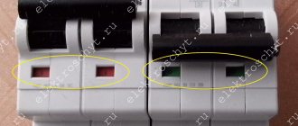
- UZO-VAD2 version A: On the front panel in each pole there are indicators of the state of the main contacts (green - contacts are open, red - closed).
- The sealing of UZO-VAD2 version A is made with a plate.
| Indicators | Quantities |
| Rated mains voltage, V | 380 |
| Rated frequency, Hz | 50 |
| Number of poles | 4 |
| Rated current, A | 10, 16, 20, 25, 32, 40, 50, 63 |
| Rated differential current, mA | 30, 100, 300, 500 |
| Rated maximum making and breaking capacity (PKS), A | 10000 (for 10 ÷ 40A) 6000 (for 50 and 63A) |
| Shutdown time at double value of the rated shutdown differential current, no more than, sec. | 0.04 (general type) 0.20 (S type) |
| Maximum cross-section of connected conductors, mm2 | 25 |
| Temperature range, °C | from minus 45 to 55 |
| Overall dimensions, mm | 110 x 76 x 88.5 |
| Weight, no more, kg | 0,75 |
Operating manual Certificate of conformity
Source: https://www.sibmera.com/nizkovoltnaya-apparatura/ustroystva-zaschitnogo-otklyucheniya/ustroystvo-zaschitnogo-otklyucheniya-trehfaznoe-uzo-vad2-trehfaznoe
The most common series of domestic and foreign AB models
One of the most popular series of circuit breakers on the market presented by foreign manufacturers is the c60n series.
Features of c60n circuit breakers:
- C60n machines comply with the requirements of domestic and international standards.
- c60n devices are designed to operate in single-phase and three-phase networks.
- C60n machines have a wide range of capacities, which includes products with a rated current from 0.5 to 125A.
- Depending on the purpose, c60n circuit breakers can have from one to four poles.
- Unlike most similar devices, c60n machines have an unambiguous status indication.
- Time-current characteristics of c60n devices can be of type B, C and D.
- Breaking capacity up to 20 kA (depending on the type of circuit breaker marked c60n).
- The maximum breaking capacity of c60n circuit breakers is 6 kA.
The most popular types of domestic circuit breakers include devices of the ae series, which include devices of the ae 2036, ae 2043, ae 2046, and ae 2056 types.
Features of ae series switches:
- Ae circuit breakers are used in three-phase AC networks.
- The main function of ae type machines is to protect consumers such as asynchronous electric motors.
- Ae series circuit breakers provide a large selection of shutdown parameters, which include the operating current setting value. For example, for an ae machine with a rated current of 40A and a setting of 12, the operating current will be equal to 40X12=480 A.
- The maximum switching capacity of automatic machines ae 2046M is 4500A.