Are there people who have never had their charger cable break?
Everyone is familiar with the tips for increasing the service life of the cord: installing a regular small spring at the base of the plug, minimizing bends, careful storage, and so on. But all (or almost all) of these actions only delay the day when there will be a need to go to a mobile electronics store for a new accessory.
When buying a USB cable, a logical question arises: which one to choose so as not to make a mistake? The answer depends on many factors, because for some people the charging speed is important, and for others the main thing is that the color of the cable matches the new case. Let's figure it out.
MicroUSB
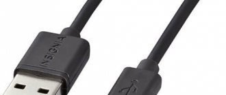
The most famous and popular of these solutions is the MicroUSB connector, which allows not only charging the device, but also transferring data. With its spread, there is no longer a need to have its own charger for each gadget, and the MicroUSB/USB Type-A cable has become a universal way to connect a smartphone to both a charger and a computer or laptop.
Important: the phone charges much slower from a PC than from a charger connected directly to an outlet. If you want to charge your device as quickly as possible, put it in airplane mode and use the charger.
The dimensions of the connector are only 7x2 mm. It was compactness that became one of the main factors that played in its favor when manufacturers were choosing between MicroUSB and MiniUSB options. The standard provides power up to 2.5 W and allows you to fully charge the phone in 1-5 hours, depending on the battery capacity, as well as the characteristics of the charger and the device itself. The maximum data transfer rate through such a connector in theory can be up to 480 Mbit/s, but in practice it is limited by many factors and can be several times lower.
In 2009, 13 companies producing smartphones and other digital equipment, including such large ones as Samsung and Apple, signed a document confirming their intention to standardize connectors and interfaces. The reasons are not only marketing, but also political, as well as reputational - European authorities have repeatedly called on manufacturers not to increase the number of different chargers, which then need to be recycled or disposed of.
About a year later, the European Parliament published a statement officially calling on mobile device manufacturers to switch to a single standard. This policy of representatives of various states played a role in securing microUSB as a universal connector for charging gadgets and transferring files. Only a few companies abandoned it. The most famous among them is Apple.
Check the current capacity of the cord
The original cords are designed for the current supplied by the charger. When purchasing a cheaper accessory, be sure to check what current this cable can carry. If, for example, the charger produces 2 A, but the cord can only transmit 0.6–0.7 A, then the charging time of the smartphone will increase significantly, and in some cases the gadget may not charge at all. Sometimes, due to such cords, the smartphone battery fails.
The current strength that the cable conducts can be indicated on the packaging of the accessory or given in the product description in the online store.
OTG standard
Many models of smartphones and tablets can be connected to the same models of flash drives as a PC - you only need the device to support the OTG standard and a special adapter.
Using it, you can connect to your phone not only a compact flash drive, but also a computer mouse, keyboard or gamepad. The adapter is also suitable for connecting a printer - documents and pictures can be printed directly from a mobile gadget.
USB cable specifications
Material, presence of light indicators, length and a bunch of other factors are pricing parameters. It is important to understand what of all this is really necessary.
Material. A very important parameter, and this refers to both the material of the plug (plastic or metal) and the cord itself, which can be wrapped in fabric. It’s not only pleasant to look at, but also to know that the cable will last several times longer.
Form. It is also an important factor on which the lifespan of the accessory depends. So, there are three main shapes: round, flat and the so-called “spring”. The round shape has a low cost compared to its rivals, and that’s where its advantages end. The flat shape is different in that it hardly gets tangled (at least less than the previous one) and does not take up space in your pocket/backpack/any other place where the cable is stored. You just need to roll it several times to make it compact. Last on the list, but not least, is the “spring” option. It is compact, convenient and original, but if it somehow gets tangled, it may take several minutes to restore its previous shape. The cheapest cable will be round, the most expensive will be spring-shaped.
Length. Selected exclusively individually. What depends on the length? The charging speed of a shorter cable is higher, but not significantly (in fact, it is not noticeable). It is logical to choose a long wire if the outlet is located far from the sofa/nightstand/bed/any place where the smartphone is charged.
Light indicators. LEDs built into the plugs that light up when the smartphone is connected to a charger or any other device. This is more of an overpayment and a kind of “gadget” than a useful thing.
Color. In terms of characteristics, this factor does not affect anything. Sometimes users try to choose a power supply and cable of the same color for aesthetic reasons. There is no other meaning to this. A white cord is easier to find in the dark, in a car, or in a mess, but it gets dirty noticeably more often. No matter how beautiful the colors are, they are not worth the overpayment, because the iridescent wire will not charge the phone faster.
All of the above parameters have a greater impact on price than on quality, so there is no need to focus on them.
Lightning
Previously, the Cupertino company's mobile gadgets used Apple's proprietary 30pin standard, but since 2012 it was replaced by the eight-pin Apple Lightning connector, which is similar in charging and data transfer speeds to MicroUSB. Calls from officials and the media did not lead to the abandonment of its own connector; instead, the company released a number of adapters with which you can charge your iPhone using regular USB chargers.
Pinout diagram
Assignment of micro-USB connector contacts - socket and plug
The USB (Universal Serial Bus) connector is a universal-purpose serial bus, the most common wired method of connecting external devices to a computer. This connector allows you to organize data exchange between a computer and a video camera, card reader, MP3 player, external hard drive, or smartphone.
USB cable pinout by color
The cable description indicates its default plug orientation. The pinout is determined by the outside. If it is necessary to describe the structure from the installation side, this fact must be noted in the technical documentation. Insulating areas are marked dark gray on the connector and light gray on the metal part of the housing.
We recommend reading: Types of batteries: detailed classification of batteries by size, composition and other parameters
Purple markings are used on charging wires and DATA cables.
Pinout is necessary to identify a faulty line during repair. It indicates the purpose of a particular component.
USB 2.0 connector pinout
Since the physical plugs and sockets of early versions 1.1 and 2.0 do not differ from each other, we will present the wiring of the latter. Below is a diagram of the wiring of the plug and socket of the Type A connector:
Designations:
- A - nest.
- B - plug.
- 1 - power supply +5.0 V.
- 2 and 3 signal wires.
- 4 - mass.
In the figure, the coloring of the contacts is shown according to the colors of the wire, and corresponds to the accepted specification.
- Reobass circuit for PC
Now let's look at the wiring of the classic socket B.
Designations:
- A - plug connected to the socket on peripheral devices.
- B - socket on a peripheral device.
- 1 - power contact (+5 V).
- 2 and 3 - signal contacts.
- 4 - ground wire contact.
The colors of the contacts correspond to the accepted colors of the wires in the cord.
Technological structure of the USB 2.0 interface
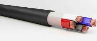
Connectors related to products included in the specification group 1.x - 2.0 (created before 2001) are connected to a four-core electrical cable, where two conductors are power and two more are transmitting data.
Also, in specifications 1.x - 2.0, wiring of service USB connectors requires the connection of a shielding braid - in fact, a fifth conductor.
This is what the physical design of normal USB connectors belonging to the second specification looks like. On the left are the “male” type versions, on the right are the “female” type versions and the pinout corresponding to both options
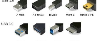
Existing versions of universal serial bus connectors of the noted specifications are presented in three options:
- Normal – type “A” and “B”.
- Mini – type “A” and “B”.
- Micro – type “A” and “B”.
The difference between all three types of products lies in the design approach. If normal connectors are intended for use on stationary equipment, “mini” and “micro” connectors are made for use in mobile devices.
This is what the physical design of the connectors of the second specification from the “mini” series looks like and, accordingly, the label for Mini USB connectors - the so-called pinout, based on which the user makes the cable connection
Therefore, the last two types are characterized by a miniature design and a slightly modified connector shape.
Pinout table for standard type “A” and “B” connectors
| Contact | Specification | Cable conductor | Function |
| 1 | Power + | Red (orange) | + 5V |
| 2 | Data - | White (gold) | Data – |
| 3 | Data + | Green | Data + |
| 4 | Nutrition - | Black blue) | Earth |
Along with the execution of connectors of the “mini-A” and “mini-B” types, as well as connectors of the “micro-A” and “micro-B” types, there are modifications of the “mini-AB” and “micro-AB” type connectors.
A distinctive feature of such designs is the wiring of the USB conductors on a 10-pin pad. However, in practice, such connectors are rarely used.
Micro USB and Mini USB interface pinout table for type “A” and “B” connectors
| Contact | Specification | Cable conductor | Function |
| 1 | Power + | Red | + 5V |
| 2 | Data - | White | Data – |
| 3 | Data + | Green | Data + |
| 4 | Identifier | – | Host - device |
| 5 | Nutrition - | Black | Earth |
Connector diagram for USB 2.0
In the diagram you can see several connectors that differ from each other according to a certain characteristic. For example, an active (power) device is designated by the letter A, and a passive (connected) device is designated by the letter B. Active devices include computers and hosts, while passive devices include printers, scanners, and other devices. It is also customary to separate connectors by gender: M (male) or “male” is the plug, and F (female) or “female” is the connector socket. There are formats by size: mini, micro and without marking. For example, if you see the designation “USB micro-VM”, this means that the plug is designed to connect to a passive device in micro format.
We recommend reading: DIY generator voltage regulator relay: diagram
To pin out sockets and plugs, you will need knowledge about the purpose of the wires in a USB cable:
- The red VBUS (“plus”) carries a constant voltage of 5 Volts relative to GND. The minimum electric current value for it is 500 mA;
- the white wire is connected to the negative (D-);
- the green wire is attached to the “plus” (D+);
- The black color of the wire means that the voltage in it is 0 Volts, it carries a negative charge and is used for grounding.
In mini and micro formats, connectors contain five contacts each: red, black, white and green wires, as well as ID (which in connectors of type A is shorted to GND, and in connectors B is not used at all).
Sometimes you can find a bare Shield wire in the USB cable. This wire has no number.
If you use a table in your work, the connector in it is shown from the outside (working) side. The insulating parts of the connector are light gray, the metal parts are dark gray, and the cavities are marked white.
In order to carry out the correct USB wiring, you need to mirror the image of the front part of the connector.
Connectors for mini and micro USB formats consist of five contacts. Therefore, the fourth contact in type B connectors will not have to be used in operation. This contact in type A connectors is connected to GND, and the fifth is used for GND itself.
As a result of some simple manipulations, you can independently make pinouts for USB ports of different formats.
USB wiring version 3.0 is distinguished by the addition of four colored wires and additional grounding. Due to this, the USB 3.0 cable is noticeably thicker than its younger brother.
Schemes for connecting USB devices to each other and wiring the device plugs:
- PS/2 To USB port
- Joystick Defender Game Racer Turbo USB-AM
- Wiring usb am and micro usb bm, for charging and transferring data to a computer
- USB-OTG
- USB wiring SAMSUNG GALAXY TAB 2
Pinout of USB 3.0 connectors (types A and B)
In the third generation, peripheral devices are connected via 10 (9 if there is no shielding braid) wires; accordingly, the number of contacts is also increased. However, they are located in such a way that it is possible to connect devices of earlier generations. That is, the +5.0 V contacts, GND, D+ and D-, are located in the same way as in the previous version. The wiring for Type A socket is shown in the figure below.
Designations:
- A - plug.
- B - nest.
- 1, 2, 3, 4 - connectors fully correspond to the pinout of the plug for the USB 2.0 type B version, the colors of the wires also match.
- 5 (SS_TX-) and 6 (SS_TX+) connectors for data transmission wires via the SUPER_SPEED protocol.
- 7 - ground (GND) for signal wires.
- 8 (SS_RX-) and 9 (SS_RX+) connectors of wires for receiving data via the SUPER_SPEED protocol.
The colors in the figure correspond to those generally accepted for this standard. As mentioned above, a plug from an earlier model can be inserted into the socket of this port; accordingly, the throughput will decrease. As for the plug of the third generation of the universal bus, it is impossible to insert it into the sockets of the early release.
- Maybe,
USB Type-C
The standard designed to replace the aging microUSB is USB Type-C. The maximum theoretical data transfer rate through this connector is up to 10 Gbit/s, which is provided by a contact group with 24 pins. However, it all depends on the implementation in a specific device model - if the manufacturer did not provide support for USB 3.0 or 3.1, limiting itself to USB 2.0, then there will be no increase in speed compared to MicroUSB. By the way, the dimensions of the connector are 8.34×2.56 mm. A little more than MicroUSB, but this is a small price to pay for the multiple performance gains: USB Type-C remains very compact and can be used in almost any device.
An additional advantage of the updated interface is the symmetry of the oval connector. Now users will not have to turn the plug over several times, swearing at engineers who are not familiar with the concept of “usability”. The charging speed has also increased noticeably, and the maximum theoretical power supported by the interface (with USB 3.1) reaches 100 W, but this option requires advanced implementation - standard profiles are limited to 7.5-15 watts. The declared mechanical resource is no different from MicroUSB and is about 10,000 connections.
USB connector compatibility
If we talk about the compatibility of USB connectors with each other, then the first and second types of USB connectors are compatible with each other. If you connect a device designed to work with USB 2.0 into connector 1.1, the user will receive a system message stating that this device can work faster (it will work, although not as fast as it would with 2.0).
USB 2.0 and 3.0 connectors are also partially compatible; you can easily plug a device designed for a 2.0 connector into a 3.0 connector, and it will work. However, you cannot plug a device designed for a 3.0 type connector into a 2.0 connector.
USB Type-C and USB 3.1 - what is the difference
It is necessary to distinguish the connector form factor from the data exchange standard. For example, the USB Type-C format can comply with different specifications - USB 2.0, 3.0 or 3.1. In the first case, it is capable of transmitting data at speeds of up to 480 Mbit/s, and in the latter – up to 10 Gbit/s. MicroUSB connectors on smartphones comply with the USB 2.0 standard.
The actual information transfer speed is usually several times less than the maximum and can be limited not only by the supported standard, but also by the cable, the port of a smartphone, tablet or computer, the performance of the controller and memory, so the theoretical limit is unattainable in real use scenarios.
Based on the above, the presence of a USB Type-C connector on a device does not guarantee high charging and data transfer speeds. The current version of the interface should be clarified in the technical specifications of specific devices, and then compared with user experience - thematic forums and other specialized resources will help with this.
Conclusion
Almost all modern smartphones and tablets are equipped with a microUSB connector (all of them comply with USB 2.0 specifications) or USB Type-C with support for USB 2.0, 3.0 or 3.1. Some of them have a fast charging function that requires a compatible charger - the implementation options in models from different manufacturers in this case differ. MicroUSB is slowly moving into the category of a connector for low-cost devices, and USB Type-C is now found not only in flagship smartphones, but also in mid-price gadgets, and sometimes in budget phones. At the same time, buyers should not let their guard down - before purchasing a new device, they should familiarize themselves with its characteristics and clarify which version of USB a particular model supports, if it is equipped with a USB Type-C connector.
An exception that does not use microUSB or USB Type-C is the iPhone - Apple smartphones have a proprietary Lightning connector instead, and to charge them using the USB interface you need an adapter cable.
Types of USB connectors
By purpose
According to its purpose, any USB port can be classified into one of three types:
- Standard or regular, which provides power and information exchange between devices. Computers, laptops, smartphones, TVs, etc. are equipped with such ports.
- Charger. They are found on chargers, power banks and some system units and are intended only for powering peripherals.
- Dedicated charger. These sockets are used to charge USB gadgets from a household electrical outlet. They are built into electrical outlets. An example of such a solution is shown in the photo below.
The first type can be of any version, the second and third most often refer to versions 2.0 or 3.0. The latter differ in color.
By configuration
The configuration of the connectors is also “tied” to the generation of the interface. USB plugs and sockets versions 1.1 and 2.0 come in the following sizes and shapes:
- Type A (standard). Such ports are installed on host and charger devices. They come in three sizes: regular (the most common is 12x4 mm, 4 pins), medium (miniUSB 7x3 mm, 5 pins) and small (microUSB 7x2 mm, 5 pins).
- Type B (narrow). Peripheral equipment is equipped with sockets of this type. They can also be regular (7x8mm, 4 pins), mini (3x7mm, 5 pins) and micro (2x7mm, 5 pins).
Micro connectors of both types are visually very similar. The only difference is that A has the shape of a rectangle, and B has beveled upper corners.
It is rare, but there are USB cables that are equipped with combined connectors: mini-AB and micro-AB. They can be connected to sockets of either type.
USB 3rd generation connectors come in the following sizes:
- A – standard. It differs from its predecessor in color and number of contacts; here there are 9 of them. The micro-A connector has 10 contacts and is divided into 2 parts. Half are identical to microUSB 2.0 (for compatibility), the remaining 5 pins are located in another part. This was done because the compact size did not allow all the pins to fit in one place. There are no mini-A 3.0 connectors.
- B - its standard and mini connectors are identical in configuration to USB-B version 2.0, but also have 9 pins each. Micro-B differs from micro-A in the shape of the combined half. It, like microUSB-B 2.0, has cut corners.
Third generation microUSB interfaces are not very common because they are extremely inconvenient to use. In addition, sockets of this type often cannot withstand repeated tugging back and forth and break off from the carrier. Their predecessors also suffer from the same drawback, but here the problem arises more often.
However, this does not mean that miniature USB-3 connectors will have to be abandoned. A replacement for the unsuccessful solution has already been found - a new and radically different USB Type C interface.
This is interesting: More powerful, faster, more convenient: pros, cons and features of USB Type-C
Features of USB Type C
Type-C or simply USB-C is a compact third generation USB connector (8.4 x 2.6 mm, 24 pins) that is designed for the same tasks as its predecessors. Unlike all other interfaces of this type, it is symmetrical or double-sided, that is, it supports cable connections on both the top and bottom sides, like the Lightning connectors on Apple devices.
Eliminating the need to orient the cable in the desired position reduces the risk of breakage of the socket, extends its service life and makes life easier for people with impaired vision and poor coordination of movements, who for these reasons cannot use devices with microUSB-B connectors.
The Type-C specification complies with USB 3.1 and ensures full compatibility with earlier versions of this interface, as required by the standard. Therefore, mobile gadgets equipped with such sockets do not always support third-generation speeds: the newfangled connector is quite capable of coexisting with a USB controller version 2.0.
Another feature of USB-C is its support for alternative modes of operation as HDMI and MHL interfaces (a hybrid of HDMI and microUSB), DisplayPort, VGA and Thunderbolt. Thanks to this feature, a smartphone with Type-C can be connected, for example, to the HDMI port of a TV or the DisplayPort input of a computer monitor. Of course, the ability to communicate via such a channel must be implemented in a device with USB-C, which is currently only found on top-end smartphones. However, the technology has prospects.
USB 3.0 pinout
Let's start with the fact that USB 3.0 is much more powerful than 2.0. The current strength of 3.0 is up to 900 mA, which allows you to charge the device much faster, as well as more gadgets. Despite the fact that the 3rd generation is newer, its wire is thicker and shorter in length. There are problems with support on the OS. The fact is that not all operating systems want to use it, since it is the most expensive of the possible options. But even its high cost is compensated by one significant fact - information is transferred in two directions at maximum speed.
USB 3.0 contains 5 pins.
The USB 3.0 pins on the board are diagonal.
USB pinout by color
USB has pins designated by colors. In the usual version, the connector has 4 contacts, and in mini and micro - 5.
- The red +5V conductor is for power supply (maximum supply current does not exceed 500 mA). Voltage +5V relative to the GND pin.
- The black contact is for ground. The value is 0V.
- The white contact is connected to the minus.
- The green contact is connected to the positive.
The order in the classic version of the contacts is as follows: red, white, green, black.
In mini and micro: red, white, green, ID (can be designated in any way - purple, black cross on a white background), black.
The ID contact works differently in the two types. For example, in type A it must retain the OTG function, but in type B it does not.
Micro USB connector
Description
Considering what types of connectors there are, let's start with the most popular. One of the most common charger options these days is the micro USB connector. This version of charging appeared thanks to the use of advanced technologies and modern developments. Externally, this connector is distinguished by its small size and flat shape compared to classic adapters for USB cables. The dimensions of the device are only 7 × 2 mm, and the power consumption is 2.5 W. Moreover, using the presented version of the charger, you can charge the battery in about 1–5 hours, depending on the current source and battery characteristics.
Thanks to the advent of this device, it became possible not only to charge the phone, but also to transfer data via a wired connection. Also, thanks to the universal cable, you can charge the device from an outlet, computer or laptop.
USB Mini and Micro Type B
USB Micro-B Connector
Mini-USB connectors were first introduced in 1998 for electronic devices such as early smartphones and tablet computers. While Mini-A connectors have long been discontinued, Mini Type-B is still supported by a small number of devices.
Micro-USB connectors are designed specifically for modern portable devices such as smartphones and cameras, which are much thinner than earlier devices. The thickness of the Micro-USB connector is almost half that of the Mini-USB.
Where is USB used?
As an industry standard, USB cables are used to connect desktop or laptop computers to external hardware devices such as keyboards, mice, flash drives, printers, and game controllers.
USB interface has become so popular in recent years that you can easily find them even in cars and electrical outlets in homes. Modern smartphones, tablet computers and many portable devices now support USB cables and connectors for faster charging than other types of cables.
USB 2.0 pinout
USB 2.0 is the most common connector. Supported on all OS (which cannot be said about 3.0). It is very convenient, because its wire is thin and long. The current is 500 mA, which is quite low, since there are already more advanced USB models on the market that provide fast data transfer.
Now the question remains, how does this device function? The work occurs through an asynchronous serial protocol, which implies that there is no common clock between the addressee and the sender. Any device that connects to a USB port works through this protocol. If the microcontroller or microprocessor has the ability to support a USB host, then it allows us to connect any USB device, such as a keyboard, etc.
To make communication between this device and the host (uP or uC) when a USB device is connected, first the device descriptor tells the host what the vendor ID and product ID is, which is used to load a specific driver for the device, then comes the configuration descriptor, which mainly used to determine power consumption values, then there is an interface descriptor, the host device can be a printer, scanner or USB flash drive, this descriptor is responsible for determining what kind of device it is, finally there is an endpoint descriptor; this descriptor is used to determine the speed of the transfer type, the throughput of the packet size, etc. There are four endpoints for a low-speed USB 2.0 device and 16 for a high-speed USB 2.0 device.
Let's talk about D. There are two of them, (+ and -), since USB C is supposed to be returnable. If you connect the plug both ways, it will be considered a valid USB 2.0 connection because USB 2.0 does not do pinning negotiation. Rotate the plug 180 degrees and these pins are connected in the same order. Your board should connect both together for maximum connectivity.
There is no identification pin, as it is only used on plugs. In USB C, the CC pins handle this, and connecting them to GND with a 5K resistor creates OTG HOST mode on the opposite side of the connection.
USB 2.0 has 4 pins.
On this pinout you can see the distribution of pins on the motherboard. It can be seen that the red contact is 1 and 2 divisions, white is 3 and 4, green is 5 and 6, black is 7, 8, 10. There is no 9 contact here. The contacts are located below each other.