Why do you need a wiring diagram?
It turns out that installing modern electrical wiring in an apartment is a real art, which only a professional electrician can handle.
If you do not want to constantly change the decoration of the walls in order to mask cables that appear here and there, we recommend that before renovating an apartment or building a house, draw up a drawing indicating all significant objects related to electricity: sockets, switches, an electrical panel with an RCD, lighting fixtures.
A sample diagram that a homeowner can sketch
Attention is paid to marking the locations of all electrical points, from the electrical panel to the sockets. Focusing on the requirements or wishes of the home owner, the electrician draws up a schematic diagram of the electrical wiring in the apartment
His task is to divide the cables into groups in order to correctly distribute the load, think through the control and protection system, and ultimately do everything to guarantee safety and comfort.
Based on the requirements or wishes of the home owner, the electrician draws up a schematic diagram of the electrical wiring in the apartment. His task is to divide the cables into groups in order to properly distribute the load, think through the control and protection system, and ultimately do everything to guarantee safety and comfort.
What must be taken into account when drawing up a diagram, drawing, work plan necessary for proper installation of electrical wiring?
Let's consider the electrical network from the point of view of its component parts:
- Automatic protection devices installed in the electrical panel. The functioning of all home equipment and the safety of users depend on their quality and proper installation.
- Cables and wires with the correct cross-section and good insulation.
- Sockets and switches with high-quality contacts and safe housings.
In private houses, a mandatory element is an input circuit breaker and a power cable from it to the switchboard. Using a circuit breaker, the power consumption is regulated and, if necessary, all electricity in the house is turned off.
Approximate wiring diagram in a private house
The main attention should be paid to the distribution of power across circuit breakers and the protection of each dedicated line. The electricity meter is usually installed at the entrance, after the input circuit breaker
The electricity meter is usually installed at the entrance, after the input circuit breaker.
Sequence of installation work
Wiring installation begins after drawing up a diagram and purchasing cables and components.
Installing a ground loop
Private houses are equipped with an element that:
- protects the user in case of current breakdown on the device body;
- ensures the safe operation of devices operating in a humid environment;
- prevents interference in the electrical network.
Private houses are provided with a grounding loop.
The circuit is installed in the ground, and in the house the grounding is connected to the electrical panel. Mandatory protection is required:
- powerful household appliances;
- lighting fixtures in rooms with high humidity.
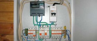
Switchboard elements
This block contains:
- general RCDs and protective elements;
- individual line machines;
- metering devices;
- zero and ground bus.
Related material: RCD connection diagram
The functions of the core in the shield are determined by the color of the braid:
- blue - zero;
- white (brown or black) - phase;
- yellow-green - grounding.
Distribution board is a device for receiving and distributing electrical energy.
The final assembly of the shield is carried out after laying the wiring.
Installation of electrical wiring of open and closed type
Electrical networks in a new building are laid in 2 ways:
- Open, in which the wires are fixed to the walls. The advantage of this method is constant access to the wiring. Open styling is not compatible with all interiors. The cable is fixed with staples and, if necessary, covered with a box. The holes for installing the socket are made with a drill or a hammer drill.
- Hidden, which requires wall chipping. The wires are hidden behind the facing material. This method of electrical installation is considered more reliable, but labor-intensive and difficult for novice electricians.
What does the PUE say about the difference between group networks and supply and distribution networks?
The main document for an electrician, PUE (Rules for the Construction of Electrical Installations), surprisingly clearly and reasonably interprets the concepts of group, distribution and supply networks in Chapter 7 (clause 7.1.10-7.1.12)
- The power supply network goes from the substation switchgear or branch from the overhead power line to the input, input-distribution devices, and the main distribution board.
- The electrical distribution network follows the supply network to distribution points and electrical panels.
- And finally, the group network (circuit), it follows the distribution network, from panels to electrical receivers (lamps, sockets, etc.).
As we can see from the clear definitions, the group networks of an apartment start from the floor or apartment electrical panel to the apartment’s electrical receivers.
Implantation (“freezing”) of electrical cables
We moisten the recesses for the sockets with water, prepare the sockets for installation (break out the perforations for the cables), spread the alabaster, level the sockets by “freezing” them with diluted alabaster. We also secure the cable with alabaster after 30-50 cm. After the alabaster has hardened (2-3 minutes), the grooves and sub-walls can be sealed with gypsum plaster.
Several additions
- Connect old aluminum wires to new copper wires through electrical connection terminal blocks.
- The ends of the stranded wires are crimped with a sleeve using special pliers. It is possible to twist stranded cores with subsequent soldering of the twist.
- When installing sub-walls under the tile “apron” in the kitchen, make sure that the sub-walls stick out from the wall to the thickness of the tile with mortar (8-10 mm).
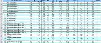
- Before laying electrical cables, as well as after freezing them with alabaster, measure the insulation resistance of the electrical cable. They must match and be within the limits indicated in the table below.
The insulation resistance for apartment electrical wiring is measured using an Ohmmeter with an output Voltage of 500 Volts, at a temperature not lower than +5°. And as can be seen from the table, it should not be less than 0.5 MOhm.
That's all about dividing electrical wiring into groups! Good luck to you in your endeavors!
Especially for the site: Everything about apartment renovation
Methods for routing wires and cables
Choosing a method for distributing wires in a home electrical network is a very serious and responsible undertaking. This largely determines how all the electrical equipment in the apartment will function in the future.
The most popular method of wiring is to connect all components of the electrical network through distribution boxes. This installation diagram provides for an electrical panel installed outside the apartment on the landing. An electric meter and circuit breakers are installed in it. Next, a cable with a certain cross-section is laid from the panel, which is brought into the apartment. From it, using distribution boxes, wires are routed to each room according to a pre-designed diagram.
Another method involves a star connection. With this connection, each point - socket or lighting fixture - is powered from a separate cable line. Each line is connected directly to the panel, in most cases, together with a separate circuit breaker. This type of wiring is characterized by a significant increase in the number of wires and cables, as well as labor costs for their arrangement. Ultimately, the project becomes more expensive. However, if we fully take into account all the positive and negative aspects, we can conclude that such a system is much more reliable than a conventional one and allows you to control every element in the electrical circuit.
The “loopback” system is considered a cheaper connection. It is similar to the “star” option and differs in the ability to connect several consumers to one cable at once. This method is used in accordance with the individual characteristics of the premises and the entire apartment. In any case, each of these methods is rarely used in its pure form. As a rule, combined options are used in the circuits, which allows for the most efficient and safe wiring of home electrical wiring.
Selection of protective automation
I advise you to buy circuit breakers from three manufacturers for installation: LEGRAND, ABB and DEKraft.
Automatic DEK Kraft
Legrand automatic
ABB automatic
All machines are mounted according to the DIN system (mounted on a DIN rail, simply snapped into place) and have a fuse (load current switch) from 10 to 63 Amps. There are also large denominations, but they are not needed in an apartment. Circuit breakers differ in the time they are disconnected from the load and the coating of the clamping contacts.
mounting machines on DIN rail
- ABB automation has all copper clamps, which is excellent in itself; the shutdown time is minimal.
- The LEGRAND automatics have all the clamps copper-plated, which is also not bad, the shutdown time is minimal.
- DEKraft automatics have all metal clamps, the shutdown time is several milliseconds longer than ABB AND LEGRAND.
The choice of automation for protecting lines must be treated with special care. The safety of your home depends on it. Therefore, I advise you to buy circuit breakers in specialized stores. (Read the article HERE and HERE about the installation of the Electrician)
Distribution of consumers by groups
In addition to connections and connections, the distribution of all consumers located in the apartment into separate groups in accordance with their purpose is of great importance. Typically, the wiring diagram is made on different sheets, where each sheet corresponds to one group.
Such a breakdown will be even more effective when each group of consumers is connected to a separate circuit breaker. With this technical solution, in the future it becomes possible to carry out repairs of electrical equipment without completely turning off the power, but only in the part of the apartment where the work will be performed. In addition, separate lines have another important advantage: they do not require a high-power cable that can withstand high loads. Such loads necessarily arise when several consumers are connected to one line at once.
An electrical panel located directly in the apartment makes it possible to connect each consumer to a separate machine. This scheme makes the operation of the network convenient and safe, solving in advance all problems that may arise in the future.
The standard division into groups could be as follows:
- Only lighting for living rooms, kitchens and corridors.
- Connecting power to living rooms.
- Connecting power to the kitchen and hallways.
- Lighting and power supply are separately connected to rooms with high humidity - the bathroom and toilet. This group should be highlighted because increased requirements are placed on it.
- If the kitchen has an electric stove, it must be connected to a separate line.
Additional safety is ensured by installing a separate residual current device (RCD) on each group, which is also known as a residual current switch. These devices must be installed in the kitchen and bathroom lines.
After the groups are formed, the places where the main electricity consumers will be connected are determined. These include electric stoves, washing machines, water heaters, air conditioners, dishwashers and ovens. The installation locations of sockets, switches, lighting fixtures and distribution boxes are marked on the preliminary electrical diagram of the apartment. Next, a conditional connection of the wires is made, and their length in each section is also marked on the diagram.
After preliminary sketches, a final version of the diagram is drawn up. It is applied to a precise floor plan: electrical devices are indicated by special symbols, and wires are marked with multi-colored lines so that power cables, lighting and grounding can be distinguished from each other. The diagram must contain the maximum number of sizes. The area of the rooms, the distances from the wires to the structural elements of the premises, heating and water supply systems are noted. A detailed diagram allows you not only to significantly speed up repairs, but also to calculate all the necessary materials and costs.
Electrical network parameters
It is difficult to accurately calculate wiring indicators. It is impossible to know whether the number of electricity consumers will change over time. The same applies to possible installation locations. However, you can make a rough project. Materials are purchased with a reserve, but it is not advisable to overpay for extra power.
Load calculation
This indicator is easy to calculate. Energy consumption data is available in technical data sheets. Knowing the power consumption, you can calculate the current using the formula I=P/E, where:
- P—power;
- E is voltage.
The permissible total current flowing through one line is 25 A. The circuit breakers through which the branches are connected must have this rating.
To protect lighting networks, 16 A RCDs can be used.
How to form consumer groups
Electrical wiring is divided into groups at the design stage. Before starting this work, it is necessary to mark on the apartment plan the location of sockets, lamps and powerful electrical appliances, indicating the power and current consumption.
In addition to the necessary ones, it is advisable to add several spare sockets. Sooner or later they will definitely be needed. The number of sockets in the rooms should be sufficient to eliminate the use of tees and extension cords. Instead, double sockets or a socket block are installed
Important ! Standard household sockets are rated at 16A, but the total current of electrical appliances connected to a double socket or socket block should not exceed this value. This is due to the cross-section of the supply cables
If there are no electrical installations available, the location of the proposed installation is marked. If this is not done, then when installing new electrical appliances you will have to hollow out the walls and lay additional wiring.
Electrical wiring is divided into groups according to certain rules:
- For sockets, the total current of the devices is calculated. If it exceeds 25A, then such a group should be divided into two and connected with a copper cable with a cross-section of 2.5 mm². The connection to individual sockets is carried out using a 2.5mm² wire.
- Lighting is laid with a wire with a cross-section of 1.5 mm²; a 1.5 mm² cable is also used to connect individual lamps and switches. The rated current of the lighting machine is 10A.
- Electrical appliances with a power of more than 3.5 kW are connected with a separate cable and a circuit breaker. The wire cross-section and rated current of the machine are determined by the power of the device.
- Electrical wiring in the bathroom and other wet rooms should be a separate group. It is connected via an RCD with a response (leakage) current of 10 mA. If there are several such rooms and they are located nearby, then they are connected together.
- For each group, the total current of electrical appliances is calculated and, based on this, circuit breakers and RCDs are selected. The leakage current of RCDs in ordinary premises should be no more than 30 mA.
What is it for?
Firstly, for ease of maintenance. Secondly, for the safety of electrical wiring. If any group fails, it is disabled without affecting the others. For example, with proper distribution of the electrical network, a closed heating element of the heater will not de-energize the entire house and you will not have to touch the cause of the accident in the dark or wander around the apartment or house to the switchboard.
In the old days, when designing housing, the requirements for wiring were different from today, and many electrical appliances that are now common to us were not in use. Therefore, it was considered normal and economically feasible to combine sockets and lighting into one group.
Tags: , automatic, ampere, beat, boiler, sconce, view, water heater, choice, switch, house, , clamp, grounding, sign, cable, like, computer, circuit, , installation, power, load, voltage, nominal, crimp , lighting, transfer, connection, rule, principle, wire, project, laying, start-up, work, calculation, repair, socket, switch, row, light, network, system, twisting, connection, resistance, circuit, ten, type, current, transformer, three-phase, , phase, shield, power supply, electrical panel
What to do with the introductory machine
When designing electrical wiring and dividing consumers into groups, inexperienced electricians ask the following question. If it is necessary to install 4 circuit breakers for 16A sockets and 2 circuit breakers for 10A indoor and outdoor lighting in the electrical panel, the total current of these devices will be 84A, which is much higher than the rated current of the input circuit breaker, which is 40A, and sometimes even 25A.
Maybe when dividing electrical wiring into groups, it is necessary to replace the machine with a more powerful one?
It is impossible to change the input circuit breaker to a more powerful one for several reasons:
- For each apartment or private house, the electric company allocates a certain power, which is limited by the input machine. This is done in order not to overload the supply transformers and input cables, including at the entrance.
- The rated current of the protective devices must correspond to the cross-section of the wires. Replacing these devices with more powerful ones without replacing the input cable can lead to overheating of the wires and an accident.
- In many cases, the electric company installs the input machine in a separate sealed panel. Unauthorized removal of such a seal will lead to problems with the electric company and a large fine.
- When installing electric heating or an electric stove, you must obtain permission to increase power consumption. In this case, the input circuit breaker and cable are replaced.
Information! With a significant increase in power consumption, it is advisable to replace the single-phase 220V input with a three-phase 380V and connect the groups evenly to different phases.
In fact, when dividing electrical appliances into groups, there is no need to change the input circuit breaker. The rated current of circuit breakers of individual groups shows not constant, but the maximum permissible current. For example, a 16A circuit breaker is installed in a group of indoor sockets, and the total current of the TV and mobile phone chargers is less than 1A. Even high-power devices do not work all the time, but intermittently.
Problems may arise when turning on the washing machine and dishwasher at the same time, especially together with an electric oven and electric kettle.
In this case, the total current will reach 2 kW (kettle) + 2.5 kW (dishwasher) + 2.5 kW (washing machine) + 1 kW (electric oven) = 8 kW or, in a 220V network, 36A. When the boiler or air conditioner is running, this will lead to an overload of the network and tripping of the circuit breaker. Therefore, such powerful electrical appliances must be turned on one by one.
Advantages and disadvantages
Dividing consumers into groups has advantages over connecting all devices to one machine:
- reduction of cable cross-section;
- increasing the safety of home residents;
- simplifying repairs;
- in the event of an emergency shutdown of one of the groups, the rest remain in operation;
- no need to make a complete shutdown for repairs.
In addition to advantages, separation has disadvantages:
- the calculation of electrical wiring becomes more complicated;
- the dimensions and cost of the electrical panel increase.
The complication of the input panel and installation of electrical wiring when divided into groups is justified by the convenience of further operation and repair.
Wiring diagram
When drawing up an electrical wiring diagram, it is better to make two versions of the plan: one for placing lamps, the second for sockets. Sources of energy consumption are divided into groups. For each of them, the counter will have a separate machine. The need for such distribution is associated with reducing the load on the cable. Also, if a malfunction occurs, the entire apartment will not be de-energized, but only the room in which the wiring needs to be repaired.
You can make separate groups for:
- Sockets - automatic 25A for both rooms and kitchen with bathroom
- Lighting - use a 10A machine
- For large household appliances (washing machine, electric stove, hoods, etc.) separate circuit breakers for 25A or 32A
Next, you should determine the number of outlets and their location in the apartment. First, the energy consumption points of the main appliances are assigned, then switches, lighting elements and distribution boxes. When arranging sockets and switches, you need to take into account their future comfortable use. For this:
- They should be located to the left of the entrance
- Sockets are installed 40 cm from the floor. The kitchen may have a different height
- Switches – at a height of 90 cm from the floor
When designing a typical electrical wiring, general safety requirements must be taken into account:
- You can install a socket in the bathroom only if there is a transformer
- The grounding of sockets must not be connected to the neutral wire
- An electric stove in the kitchen requires a 63 A circuit breaker.
- The cable laying path must be horizontal and vertical, at right angles
- The distance between the wires should ideally be no less than 0.3 cm, to the floor or ceiling - no less than 1.5 cm, to windows, door jambs - no less than 1 cm
- It is better to install switches and sockets throughout the apartment at the same height
- The wires are connected to sockets from below, and to switches - from above.
- If the shield is located inside the apartment, it must be placed at a height inaccessible to children
DIY wiring
The wiring in the apartment is installed using a hidden method. For this:
- Mark the wall according to the previously drawn up diagram. Indicate the locations of switches, sockets, and lamps.
- The channels are formed using a wall chaser. Lay the wires and fix them with a solution.
- Installing socket boxes. Install all components of the electrical network.
- Seal the grooves with plaster, comparing them with the surface.
When covering walls with sheet materials, gating is not required. The cables remain in the space between the trim and the walls. In this case, be sure to use corrugated sleeves, which are attached to the frame with clamps.
Apartment group circuits
In apartments, it is recommended to divide the electrical wiring circuits into (at least) three groups: a group of plug sockets in the rooms, a group of lights, and a group of sockets in the kitchen and hallway.
If the bathroom has sockets in the third zone, it is necessary to install an RCD with a cut-off current of 30 mA.
For apartments with electric stoves, a separate power supply group for the stove is provided (clause 14.12 SP31.110.2003).
The regulations indicate that in some cases, it is possible to reduce the number of apartment groups to 2 and make a mixed power supply for lighting and sockets, dividing the apartment into living rooms and a kitchen with a corridor.
Drawing up an electrical design for sockets
On a clean apartment plan, draw all the planned sockets. We are not connecting them with lines yet, but simply drawing (schematically) the planned sockets.
Next, the sockets need to be divided into group circuits (groups). You can calculate the wiring and divide it into groups theoretically. But you can use the rules of thumb for dividing electrical wiring into groups.
Practical division of electrical wiring into groups
- The total power of one group of outlets should not exceed 4300 W. This total power will allow the group to be powered using a 3x2.5mm2 (copper) cable. The electrical wiring of each such group must be protected by a 25 Ampere circuit breaker or a 20 Ampere fuse.
- For an electric stove, plan a separate power supply line, 3x6mm2 (with a stove power of up to 7300W), you need to protect the line for the stove with a 40 Ampere circuit breaker or a 32 Ampere fuse. If the stove has a lower power, then a 3x4 mm2 cable is sufficient.
- Taking into account all the stated rules, the sockets marked on the plan are connected into groups. Notes about circuit breakers are written on the plan, for example, group 1 - 25 Ampere - cable 3 × 2.5 mm2, brand VVGng.
If the number of sockets in the apartment is small, and the sockets of different rooms fall into the same group, then you need to plan to install a distribution box between the rooms. This only changes the type of wiring, but does not change the principle of drawing up an electrical project.
Wiring types
There are three types of electrical wiring:
- Using distribution boxes: the electrical panel is located outside the apartment - on the site in the entrance. A counter with several machines is placed on the panel. From the panel the cable goes to the apartment. Each room has its own junction box. They are connected to the network in series. The general scheme looks like this:
- “Star” - the electrical point is located on a separate cable line and is connected directly to a separate circuit breaker in the panel. Unprofitable in terms of labor costs and monetary expenses for laying cables and wires to each element, purchasing a more powerful reader and a large number of machines
- “Loop” - this wiring method is similar to a “star”. The difference is that on a separate cable that comes from the shield there is not one element, but a group. The diagram looks like this:
Usually several types of wiring are used at once.
How to groove the ceiling and walls in concrete and brick walls for hidden electrical wiring
Grooving is the making of grooves in the walls and ceiling for laying electrical cables, as well as hollowing out niches for electrical panels and socket boxes. The grooves can go any way, but it is more professional and practical to make the grooves at right angles. This is done in order to subsequently understand how hidden wires and cables pass and not accidentally damage them by drilling through them. For gating, you need a hammer drill with a power of 800 W or more and a powerful grinder with a diamond blade or a wall chaser.
Pre-marked grooves are cut with a diamond disc; the size of the grooves is made according to the number of cables being laid. The cuts are made along the line of cable routing and short cuts across. We hollow out everything that is not needed with a hammer drill, with attachments in the form of a peak or spatula.
We cut out recesses for sub-walls in brick and block walls with a special crown. In concrete walls, the technology for making niches for military personnel is slightly different. Mark the dimensions of the sockets on the wall. Drill a row of holes around the perimeter with a 14 mm diameter drill to a depth slightly greater than the size of the sub-socket. Hole out everything unnecessary with a hammer drill.
Connecting circuit elements together
Correct drawing up of an electrical wiring diagram in an apartment largely depends on basic knowledge of electrical engineering. Without a certain minimum, it is not recommended to engage in this rather complex work. The best option is to draw up a wiring diagram by a professional electrician. In addition to drawing up a detailed plan, the electrician can eliminate identified faults or replace worn electrical wiring along the way.
Before designing and drawing up a diagram of electrical networks for an apartment, it is necessary to find out what connection methods are used. All elements can be connected to each other in various ways:
- Serial connection. In this scheme, each element follows the previous one; there are no joints in the form of separate nodes. An example is a Christmas tree garland, where all the lighting devices are located in series on one wire. However, if at least one element in the circuit is damaged, then all other light bulbs will also stop working. This feature must be taken into account when drawing up the diagram.
- Parallel connection. In this case, the elements are not connected to each other, but are grouped into separate nodes. If any of the consumers fails, the electrical circuit will continue to function, providing current to other elements of the system.
- Mixed connection method. Parallel and series connections are used simultaneously on the same section of the circuit.