Why do you need to lay cables in trays?
Installation of cable trays is a mandatory component of the installation of protected electrical routes, regardless of their functional purpose. The advantages of placing cables and wires in special protective structures are listed below:
- mounted chains are reliably protected from mechanical damage;
- the service life of cable and wire routes is extended;
- in this case, it is possible to lay the power cable separately in a tray separated from the control (low-current) circuits by a special partition;
- simplifies access to cable products if they need to be repaired.
important:
Laying cables and wires in trays and boxes reduces the likelihood of their destruction in a fire.
In addition, they are partially protected from short circuits in the event of an emergency ingress of moisture into the internal spaces.
The disadvantages of laying cables in a tray include:
- Significant material consumption (compared to open wiring).
- Labor costs are increasing.
- There is no air circulation and dust accumulates (this only applies to products without perforation).
It is easier to prove the feasibility of using trays if you become familiar with the existing types of these structures and their functionality.
Some gasket features
- Wires or electrical cables can be laid in rows individually, in bundles, in bags or in multilayers. When laying wires in rows in one layer, the recommended clearance between adjacent wires is five millimeters. When laying in bunches or packages, the gap increases to 20 mm; when laying in multi-layers, no gap is allowed at all.
- When laying wires in bundles, it is necessary to ensure that there are no more than twelve wires in one bundle, and the diameter of one bundle should not exceed 10 cm.
- When laying wires horizontally on cable trays, it is recommended to tie them into bundles with a pitch of at least 4.5 meters. At the same time, in straight horizontal sections it is allowed not to tie the wires into bundles at all. When laying wires vertically in mounting boxes, the minimum linking step is 1 meter.
- After the metal structure of the cable-supporting route has been assembled and secured to the floors of the building with a special cord, the length of the route is measured for measuring cutting of electrical cables and wires. After cutting, the wires are grouped into bundles, bandaged and equipped with marking tags. After laying the electrical wires in trays and boxes and connecting them into a single circuit, the “phase-zero” continuity is checked and the insulation resistance is monitored with an ohmmeter.
- Laying of wires in cable trays and ducts must be carried out at a certain temperature. At ambient temperatures from -15°C and above, it is permissible to lay cables without preheating them. In the temperature range -40...-15°C, cables and wires must be preheated before laying. At air temperatures of -40°C and below, cable laying is prohibited.
- Electrical cables and wires are laid in electrical boxes with a reserve length necessary to compensate for temperature deformations and possible soil displacements. The electrical cable supply must be laid straight. Laying the stock in rings or coils is not allowed.
- When laying cables and wires openly in plastic or metal cable ducts, their possible heating under the influence of solar radiation should be taken into account. In this case, sun screens are additionally provided.
- Any cable line must be as complete as possible (laid in entire construction lengths), that is, have a minimum number of couplings.
- Electrical cables, regardless of the design of the supports, must be fastened at the end points, at connecting or end couplings and at turns of the highway. It is recommended to fasten straight sections of the cable route in increments of 1.0-1.5 meters. When laying wires in bundles, the fastening pitch can be increased to 8-10 meters.
- Installation of the electrical cable must prevent possible deformations from: • the cable's own weight; • mechanical stresses that arise from cyclic heating and cooling; • magnetic interactions that occur during short circuits.
- When crossing a cable route with a pipeline, the distance between the cable trays and the pipeline must be at least 5 cm. If they are located parallel, the minimum distance increases to 10 cm. If gas or flammable liquid is transported through the pipeline, the shortest distance to the cable tray is taken to be 25 cm .
- When laying electrical wires in a cable tray, for ease of maintenance in future operation, as well as for natural cooling purposes, it is recommended to fill no more than 50% of the volume of the electrical box.
When organizing a cable route using cable trays and ducts, you should ensure that during installation the individual elements have reliable metal contact with each other, since usually only the beginning and end of the cable support system (or one branch) are grounded.- Cable trays and ducts are mounted at a height of at least two meters from the floor or service area. In rooms where only specially trained personnel can work (for example, in electrical rooms), installation of metal trays at any height is allowed.
- The method of installation of electrical boxes and trays must exclude the possibility of moisture accumulation in them. For open laying of cables and wires, boxes with a removable lid are usually used to ensure easy access. For hidden wiring, the use of pipes and “blind” boxes for wires is allowed.
Types of cable trays
Known types of cable management trays differ based on a number of factors, which are listed below:
- The material from which the boxes are made (stainless steel, plastic, galvanized or concrete).
- Place of installation (plinths, floors, cornices, underground, etc.).
- The presence of dividing partitions.
note:
Laying cables in concrete trays is most often used when constructing underground trench routes.
For easy comparison of the characteristics of trays, their main types are presented in table form.
| Material | Advantages | Flaws | Functionality |
| Low carbon steel | Strength, resistance to mechanical deformation | Susceptibility to corrosion, difficulty of installation, significant weight. | Partitions |
| Stainless steel | Same plus corrosion resistance | Expensive | Partitions and perforations |
| Galvanization | Strength, lightness, corrosion resistance | None | Presence of perforations and partitions |
| Plastic | Cheap, light and easy to install | Low resistance to deformation, fragility | Large selection of designs, availability of partitions |
| Concrete | Strength, reliability, resistance to deformation | Significant weight, difficulty of installation, hygroscopicity | Concrete partitions, side brackets |
Additional Information:
The presence of partitions allows, according to the PUE, the laying of power cables in trays separately from low-current (control) lines.
Plastic boxes attract the attention of users with the following properties:
- in residential and work areas they can be installed at any level (near the desktop, for example, or near the baseboard);
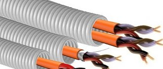
- the insides of the tray are divided by partitions into sections in which wires for various functional purposes are laid (photo on the left);
- The rules for laying cables in trays allow for their installation directly on the floor or ceiling.
Unlike plastic, the choice of placement of steel boxes is significantly limited by safety requirements in terms of electrical safety.
Hidden electrical wiring:
1. With a lining of fireproof materials and subsequent plastering or protection on all sides with a continuous layer of other fireproof materials
2. In pipes and blind boxes made of fireproof materials, steel, copper
These rules apply to a greater extent to all types of wooden houses, including the increasingly popular frame ones.
And as you can see, if in an open way, we still have the opportunity to choose how to lay electrical wires and cables, then hidden, for example, inside hollow walls or floors made of flammable materials, the main permitted method is the use of steel pipes and blind boxes with localization ability.
Localization ability is the ability of a structure to withstand a short circuit in the electrical wiring laid in it without burning through its walls.
A metal corrugated pipe does not have this ability and will not be able to fully protect you from fire in the event of a short circuit (short circuit). Therefore, it is not on the list of those permitted for laying on combustible substrates.
The simplest and most accessible of the permitted methods of laying on flammable substrates, for example, in wooden houses, include open wiring in fire-resistant cable ducts and baseboards.
In addition, there are quite elegant solutions for laying electrical wires on ceramic insulators, which can fit quite harmoniously into the interior of a wooden house.
Hidden, for example, in the walls of a frame house, for laying wires, you can make linings from any fireproof or fire-resistant materials, such as plasterboard, along which the wiring can be carried out.
I highly recommend that you do not deviate from the permitted methods of laying electrical networks for various conditions indicated here, this is your safety, you should not skimp on it.
If you have any questions or comments about what was written, be sure to write in the comments to the article. In addition, I’m really looking forward to your stories about how you do wiring, especially in wooden houses, log houses or frame houses, it will be useful to many.
Expert opinion
It-Technology, Electrical power and electronics specialist
Ask questions to the “Specialist for modernization of energy generation systems”
Typical flow chart (TTK) for laying backbone networks on trays scope - Document The most popular types of cable trays are perforated cable trays, blind cable trays, wire cable trays and ladder-type cable trays. Ask, I'm in touch!
Rules for laying cables in trays - review of standards and documents
The procedure for forming wire routes with the simultaneous installation of cable trays is regulated by the following regulatory documents and standards:
- PUE (clauses 2.1.15 and 2.1.16, clauses 2.3.122-2.3.133).
- SNiP (3.05.06-85), which stipulates the standards for laying cables in trays.
- The same category of regulatory documents includes GOSTs and other standards directly related to cable laying in trays.
important:
Before arranging cable routes, a project is prepared in which all the details of the upcoming work are prescribed.
The design documentation separately specifies the type of trays, as well as how it is allowed to install wire lines. Particular attention is paid to the permissibility of laying cables in a corrugated tray, with single cores or tied in bundles. Taking into account the specifics of the upcoming work is necessary to obtain official permission to carry out installation operations.
Prices in the estimate for laying other types of cables
In addition to the above methods for laying different types of cables, there is also a wide variety of prices for installation work on laying other types of cables. For example, prices in the estimate for a twisted pair cable, prices in the estimate for installing a heating cable, or prices in the estimate for installing an optical cable. Similar prices, as well as the prices in the estimate for laying a low-current cable or the prices in the estimate for laying UTP cable, can be applied on the basis of installation collection 10 called “Communication Equipment” or collection 08 for electrical work. The choice of price in this case must be justified by the method of laying the cable. For example, if it is necessary to apply a price in the estimate for laying a heating cable, it is important to know exactly how the installation work will be carried out and for what purposes the price in the estimate for a self-regulating heating cable should be applied. The fact is that the scope of application of the prices in the estimate for a heating cable, as well as the prices in the estimate for laying twisted pair cables, is quite wide. In this regard, choosing an unambiguously correct price without focusing on the project drawings seems quite difficult. An example of an estimate for laying a heating cable or forms using prices in the estimate for a fire-resistant cable line for specific purposes can be found on estimate forums or websites.
Among other things, when drawing up estimate forms for power lines, it is often necessary to use prices in the estimate for laying a cable along a support, prices in an estimate for laying a cable on a cable, or prices in an estimate for laying a SIP cable. In this case, most often the required prices can be found in the construction collection FER33 on power lines. So, for example, the price in the estimate for the installation of SIP cable can be applied based on table FER33-04-017. The standards in this table take into account the cost in the estimate for laying the cable openly with or without the use of hydraulic lifts.
Also, sometimes, as noted above, it is necessary to use a price in the estimate for a cable on a cable. This type of pricing can be used from table FERm08-02-149. The table contains only two standards, differing in the weight of 1 meter of cable suspended on a cable.
In addition, it should be noted that when installing a cable route, it is often necessary to take into account the price in the estimate for the breakdown of the cable line route. As a rule, the costs for this type of work are included in other prices of the collection 08.
Requirements for electrical installation rules
Taking these criteria into account, to ensure efficient operation of the cable system, it is necessary to perform a preliminary calculation of tray occupancy. To do this, refer to the rules for electrical installations. In particular, it is worth paying attention to paragraph 2.1. It states that cable products can be laid in trays in several layers, both in an ordered and random arrangement. In this case, the sum of the cable cross-section, which also includes outer sheaths and insulation, should be no more than 40% for boxes with openable covers and 35% for solid structures.
Based on the above requirement, the area occupied by one cable is calculated using the formula S = D². The letter S denotes the area of the wires, D is the outer diameter of one cable along with the outer sheath and insulation.