Positioning systems typically use one of two methods: closed-loop and open-loop systems. So what is the difference between these two approaches to positioning?
Closed-loop systems typically use servo motors to control the speed and position of a moving axis. Servo motors work just like any regular motor, when power is applied to them they rotate. This rotation takes on a continuous smooth motion. The job of a servo motor is not only to drive the motor, but also to precisely control the speed. Along with speed, position feedback is also required in a closed-loop system. This is usually provided by an encoder or linear scale. Positional feedback to the machine's controller allows it to move quickly to a target location and then smoothly slow down to settle on the target.
Open loop systems do not have a feedback device to control speed or position. Instead, the distance to be covered from the current location is divided by the machine control system into several precise steps of a certain size. The control system also determines the optimal system speed curve based on predefined parameters. The commands are then sent to the stepper motor in the form of pulses. The job of a stepper motor driver is to convert command pulses into actual motor drive steps, then the stepper motors advance through these steps to achieve the desired result.
Stepper motor operation
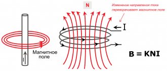
A stepper motor is a multi-winding synchronous brushless motor in which current applied to one of the stator windings causes the rotor to lock. Sequential activation of the motor windings causes angular movements (steps) of the rotor.
Stepper motors have fairly high reliability and a long service life. As the engine speed increases, the rotating torque decreases. Stepper motors produce more vibration along with other types of motors because the discrete step tends to grab the rotor from one position to another. This makes the stepper motor noisier. The vibration can be strong, which can cause the motor to lose torque because the shaft is in a magnetic field and behaves like a spring. Stepper motors operate without feedback, meaning they do not use encoders or resolvers to determine position.
There are four main types of stepper motors:
- Permanent Magnet Stepper Motors
- Hybrid stepper motor
- Variable reluctance motors
- Bipolar and unipolar stepper motors
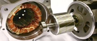
Stepper motors consist of a stator with field windings and a rotor made of soft magnetic or hard magnetic material. Stepper motors with a magnetic rotor allow you to obtain greater torque and provide fixation of the rotor when the windings are de-energized. Depending on the design of the rotor, the following types of stepper motors are distinguished: with permanent magnets (rotor made of hard magnetic material), reluctance (rotor made of soft magnetic material), hybrid. Hybrid motors combine the best features of variable reluctance motors and permanent magnet motors.
In mechanical engineering, high-torque two-phase hybrid stepper motors with angular movement of 1.8°/step (200 steps/revolution) or 0.9°/step (400 steps/revolution) are more common. The accuracy of pitch setting is determined by the quality of machining of the rotor and stator of the electric motor. Stepper electric motors are used in drives of machines and mechanisms operating in start-stop mode or in continuous motion drives, where the control action is set by a sequence of electrical pulses. Unlike servos, stepper drives allow precise positioning without the use of feedback from angle encoders. Stepper motors with permanent magnets can be used as rotation angle sensors due to the generation of EMF on the windings when the rotor rotates.
Operating principle
How a stepper motor works can be seen using a conditional model. In position 1, a voltage of a certain polarity is applied to windings A and B. As a result, an electromagnetic field is formed in the stator. Since different magnetic poles attract, the rotor will take its position along the axis of the magnetic field. Moreover, the magnetic field of the motor will prevent attempts to change the position of the rotor from the outside. In simple terms, the magnetic field of the stator will work to keep the rotor from changing the specified position (for example, under mechanical loads on the shaft).
If voltage of the same polarity is applied to windings D and C, the electromagnetic field will shift. This will cause the permanent magnet rotor to rotate to position 2. In this case, the rotation angle is 90°. This angle will be the rotor rotation step.
Position 3 is achieved by applying a voltage of reverse polarity to windings A and B. In this case, the electromagnetic field will become opposite to position 1, the motor rotor will shift, and the total angle will be 180°.
When voltage of reverse polarity is applied to windings D and C, the rotor will rotate up to 270° relative to the initial position. When positive voltage is connected to windings A and B, the rotor will take its original position - it will complete a rotation of 360°. It should be taken into account that the rotor moves along the shortest path, that is, from position 1 to position 4 clockwise, the rotor will turn only after passing intermediate positions 2 and 3. When connecting the windings after position 1 immediately to position 4, the rotor will rotate counterclockwise.
Advantages of Stepper Motor:
- Stable in operation
- Operates over a wide range of frictional and inertial loads and speeds, the speed is proportional to the frequency of the input pulses.
- No need for feedback
- Much cheaper than other types of engines
- Bearings are the only wear mechanism, due to this they have a long service life.
- Superior torque at low speeds or zero speeds
- Can handle heavy loads without the use of gearboxes
- The motor cannot be damaged by mechanical overload
- Possibility of quick start, stop, reversal
The main advantage of stepper drives is accuracy. When potential is applied to the windings, the stepper motor will rotate strictly at a certain angle. A stepper drive can be equated to an inexpensive alternative to a servo drive; it is best suited for automating individual components and systems where high dynamics are not required.
Advantages The main advantage of stepper drives is accuracy. When potentials are applied to the windings, the stepper motor will rotate strictly at a certain angle. The pleasant aspects include the cost of stepper drives, on average 1.5-2 times cheaper than servos. A stepper drive, as an inexpensive alternative to a servo drive, is best suited for automating individual components and systems where high dynamics are not required. Disadvantages The possibility of rotor slippage is the most well-known problem with these motors. This can happen when the load on the shaft is exceeded, when the control program is incorrectly configured (for example, acceleration of start or braking is not adequate to the moved mass), when the rotation speed approaches the resonant one. The presence of a sensor makes it possible to detect a problem, but it is possible to automatically compensate for it without stopping the production program only in very rare cases. To avoid rotor slippage, one way is to increase the engine power.
Control Features
To control a motor with discrete rotor motion, the following modes are used: full-stepping, half-stepping and microstepping.
Full step mode
With this method, the motor performs alternating phase switching. In this case, the phases are connected alternately to the voltage source without overlapping. The equilibrium points of the rotor with this control coincide with the poles of the stator. The disadvantages of the full-step mode include the fact that at any given time, a bipolar motor uses half of the windings, while a unipolar motor uses only a quarter. If you connect two phases at full pitch, the rotor will be fixed between the stator poles due to the supply of power to all windings. This increases the torque of the stepper motor, and the position of the rotor in the equilibrium state shifts by half a step. The step angle remains unchanged.
Half-step mode
If every second step you turn on one phase, and between that you turn on two at once, you can double the number of movements per revolution. Such commutation, accordingly, reduces the step angle by half. However, it is impossible to achieve full torque in half-step mode. The mode is actively used, as it allows you to double the number of engine steps in a simple way. It is important to consider that when voltage is removed from all phases in full-step and half-step modes, the rotor remains in a free state and can be displaced under mechanical stress. To fix the rotor, it is necessary to generate a holding current in the motor windings. Usually its value is much less than nominal. Due to the ability of the stepper motor to fix the position of the rotor when stopping, there is no need to use a braking system, clamps or other devices.
Microstepping mode
To maximize the number of motor steps, microstepping mode is used. To do this, you need to turn on two phases and distribute the winding current unevenly. When the stator's magnetic field shifts relative to the poles, the rotor itself also shifts. The disproportion of currents between the operating phases of the motor usually exhibits discreteness, which determines the magnitude of the microstep. The number of microsteps per revolution of the stepper motor rotor can be more than 1,000. A device operating in this mode can be positioned as accurately as possible. However, this control method is quite complex.
Working principle of stepper motor
Using the variable reluctance stepper motor example above, the motor consists of a central rotor and is surrounded by four electromagnetic coils labeled A, B, C and D. All coils with the same letter are connected together, so that when power is applied to, say, the coils, labeled A, the magnetic rotor aligns with this set of coils.
By applying power to each set of coils in turn, the rotor can be made to rotate or "move" from one position to another at an angle determined by the design of its pitch angle, and as the coils are energized in succession, the rotor will produce rotation (motion).
The stepper motor driver controls both the step angle and the speed of the motor by energizing the field coils in a set sequence, for example, “ADCB, ADCB, ADCB, A...” etc., the rotor will rotate in one direction (forward) and through changing the pulse sequence to "ABCD, ABCD, ABCD, A...", etc., the rotor will rotate in the opposite direction (backward).
So in our simple example above, the stepper motor has four coils, making it a 4-phase motor with the number of stator poles being eight (2 x 4), which are spaced at 45° intervals. The number of teeth on the rotor is six, which are located at a distance of 60° from each other.
There are then 24 (6 teeth x 4 coils) possible positions or “steps” for the rotor to make one full revolution. Therefore, the above pitch angle is: 360° / 24 = 15°.
Obviously, the more rotor teeth and/or stator coils, the better the control and the smaller the pitch angle. In addition, full, half and micro-step angles are possible by connecting the motor's electrical coils in various configurations. However, to achieve microjunction, the stepper motor must be driven by a (quasi) sinusoidal current, which is expensive to implement.
It is also possible to control the rotation speed of a stepper motor by changing the time delay between the digital pulses applied to the coils (frequency), the longer the delay, the slower the speed for one full revolution. By applying a fixed number of pulses to the motor, the motor shaft rotates at a given angle.
The advantage of using a time-delayed pulse is that no additional feedback is required, since by counting the number of pulses applied to the motor, the final position of the rotor will be known exactly. This response to a given number of digital input pulses allows the stepper motor to operate in an "open loop system", making it easier and cheaper to control.
For example, let's say our stepper motor has a pitch angle of 3.6° per step. To turn the motor through an angle of, say, 216° and then stop again at the desired position, it would only take: 216°/(3.6°/step) = 80 pulses applied to the stator coils.
There are many stepper motor controller ICs that can control the step speed, rotation speed and direction of the motor. One such controller is the SAA1027, which has all the necessary counters and code converters built in and can automatically connect 4 fully controlled bridge outputs to the motor in the correct sequence.
The direction of rotation can also be selected along with single-step mode or continuous (stepless) rotation in the selected direction, but this imposes some load on the controller. When using an 8-bit digital controller, 256 microsteps per step are also possible.
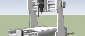
Operating principle of a 3D printer stepper motor
The motor's step angle can reach 90 degrees, which means the motor will rotate 360 degrees in four steps. However, a more typical pitch angle for 3D printer motors is 1.8 degrees, which means it takes 200 steps (360 / 1.8) to complete a full rotation.
The pitch angle is determined by the placement of the motor coils and the design of the magnetic poles in the rotor.
If it is known that it takes 200 steps to rotate the motor 360 degrees, and the motor is connected to a lead screw with 1 mm pitches (1 mm of travel for each rotation), then each step of the motor moves the axis forward by 0.005 mm. In this way, the number of steps required to reach the exact location can be easily calculated.
The calculation of the number of steps required is controlled by the controller (stepper motor driver.
Design and principle of operation
Stepper motors are widely used in household appliances, vehicles, milling and grinding machines and other manufacturing machinery.
The device is a direct current motor, one revolution of which is divided into several identical steps (this is ensured thanks to the controller). Its main difference from other types of motors is the absence of a brush mechanism.
The stepper motor is equipped with a control unit (dashboard), transmitters and signaling devices.
What does a stepper motor consist of?
How does a stepper motor work?
Knowing the operating principle of a stepper motor, you can install or repair it yourself. It functions as follows:
- After voltage is applied to the terminals, continuous rotation of the special brushes begins. Input pulses set the drive shaft to a position that is predetermined.
- Under the influence of impulses, the shaft moves at a fixed angle.
- An external control circuit, most often represented by a microcontroller, excites gear-type electromagnets. One of them (the one to which energy is applied) attracts the gear teeth to itself, as a result of which the engine shaft turns.
- Once aligned with the leading electromagnet, the remaining magnets move towards the next magnetic part.
- The rotation of the gear is ensured by turning off the first electromagnet and turning on the next one.
- The gear is aligned with the previous wheel, after which the entire process is repeated as many times as necessary.
These rotations are a constant step. To determine the speed of the motor, you need to count the number of steps required to complete its revolution. Accuracy of operation is ensured thanks to microprocessor control systems for stepper motors.
Characteristics
From the point of view of mechanics and electrical engineering, a stepper motor is a very complex device that has many mechanical and electrical parameters. I will give a breakdown of the main technical parameters that are used in practice:
- The number of complete steps per revolution. The main parameter of the engine, which determines its accuracy, resolution, and smoothness of movement. On FL57 series engines this parameter is 200 and 400 steps per revolution.
- Full pitch angle. Representation in a different form of the previous parameter. Shows the angle the shaft will rotate during one full step. Can be counted as 360° / number of complete steps per revolution. For FL57 series engines it is 1.8° and 0.9°.
- Rated current. Main electrical parameter. The highest permissible current at which the electric motor can operate for an indefinitely long time. The mechanical parameters of the motor are specified for this current.
- Rated voltage. Permissible DC voltage on the motor winding in static mode. Often this parameter is not provided. Calculated according to Ohm's law through the rated current and winding resistance.
- Phase winding resistance. DC motor winding resistance. The parameter, together with the rated current, shows what voltage can be applied to the motor winding.
- Phase inductance. The parameter becomes important at significant rotation speeds. The rate of current rise in the winding depends on it. At high phase switching frequencies, it is necessary to increase the voltage so that the current increases faster.
- Torque. Main mechanical parameter. Shows the maximum torque that the engine is capable of producing. Sometimes a mechanical characteristic is given in the form of a dependence of torque on rotational speed.
- Rotor moment of inertia. Characterizes the mechanical inertia of the engine rotor. The smaller this parameter, the faster the engine accelerates.
- Holding moment. This is the torque when the engine is stopped. In this case, the motor must be powered by two phases with rated current.
- Stopping point. The torque required to turn the motor shaft when there is no supply voltage.
- Insulation resistance. Like all electrical devices, there is resistance between the body and the windings.
- Breakdown voltage. The minimum voltage at which insulation breakdown occurs between the windings and the housing. Parameter from the electrical safety section.
Stepper Motor Driver
A stepper motor driver is an electronic power device that, based on digital control signals, controls the high current/high voltage windings of a stepper motor and allows the stepper motor to take steps (rotate). The control standard is STEP/DIR/ENABLE signals. STEP is the step signal, DIR is the rotation direction signal, ENABLE is the driver enable signal.
Controlling a stepper motor is more difficult than a conventional brushed motor; you need to switch the voltages in the windings in a certain sequence while simultaneously controlling the current. Therefore, special devices called drivers were developed to control stepper motors. They allow you to control the rotation of the rotor in accordance with control signals and in a certain way divide the physical step into smaller discretes.
The driver is connected to a power supply, a stepper motor, and control signals from the controller board. The standard for control signals is the control of STEP/DIR or CW/CCW signals and the ENABLE signal.
STEP/DIR protocol:
STEP signal - Timing signal, step signal. One pulse causes the motor rotor to rotate one step (not the physical step of the motor, but the step set on the driver - 1:1, 1:8, 1:16, etc.). Typically, the driver executes a step on the leading or falling edge of a pulse.
DIR signal - Potential signal, direction signal. Logical one - the motor rotates clockwise, zero - the motor rotates counterclockwise, or vice versa. You can usually invert the DIR signal either from the control program or swap the connection of the motor phases in the connection connector in the driver.
CW/CCW protocol:
CW signal - Timing signal, step signal. One pulse causes the motor rotor to rotate one step (not the physical step of the motor, but the step set on the driver - 1:1, 1:8, 1:16, etc.) clockwise. Typically, the driver executes a step on the leading or falling edge of a pulse.
CW signal - Timing signal, step signal. One pulse causes the motor rotor to rotate one step (not the physical step of the motor, but the step set on the driver - 1:1, 1:8, 1:16, etc.) counterclockwise. Typically, the driver executes a step on the leading or falling edge of a pulse.
Signal ENABLE - Potential signal, signal to turn on/off the driver. Usually the logic of operation is as follows: logical one (5V is applied to the input) - the stepper driver is turned off and the stepper windings are de-energized, zero (nothing is supplied or 0V is supplied to the input) - the stepper driver is turned on and the stepper windings are energized.
Stepper motor drivers may have additional features:
- Overcurrent control.
- Control of excess supply voltage, protection against the effect of back EMF from the motor. When the rotation slows down, the motor produces a voltage that adds up to the supply voltage and briefly increases it. With faster deceleration, the back EMF voltage is larger and the supply voltage surge is larger. This surge in supply voltage can lead to failure of the driver, so the driver is protected against surges in supply voltage. When the supply voltage threshold is exceeded, the driver is turned off.
- Polarity reversal control when connecting control signals and supply voltages.
- Mode of automatic reduction of winding current when idle (no STEP signal) to reduce motor heating and current consumption (AUTO-SLEEP mode).
- Automatic compensator of mid-frequency resonance SD. Resonance usually appears in the range of 6-12 rps, the motor starts to hum and the rotor stops. The onset and strength of resonance strongly depends on the parameters of the motor and its mechanical load. An automatic mid-frequency resonance compensator allows you to completely eliminate the resonance of the motor and make its rotation uniform and stable over the entire frequency range.
- Scheme for changing the shape of phase currents with increasing frequency (morphing, transition from microstep mode to step mode with increasing frequency). The stepper motor is capable of delivering the torque declared in the technical specifications only in full step mode, therefore, in a conventional stepper motor driver without morphing, when using a microstep, the stepper motor operates at 70% of the maximum power. A stepper motor driver with morphing allows you to get maximum torque output from the stepper motor over the entire frequency range.
- Built-in STEP frequency generator is a convenient function for test running the driver without connecting to a PC or other external STEP frequency generator. The generator will also be useful for building simple movement systems without the use of a PC.
Stepper motor drivers vary in complexity. Modern drivers can be combined with many different types of stepper motors. Engine-specific settings are typically configured by the user during installation. But in general, stepper motor drivers are relatively simple devices.
The illustration above shows the A4988 driver. The components' job is to respond to pulsed step commands coming from the machine controller and convert them into the correct on-off circuit needed to drive the stepper motor. This circuit activates the phases in the correct order to move the motor step by step in one direction or another.
An important point to note here is that there is very little intelligence in a stepper motor driver. This function is provided to the 3D printer controller. In fact, the driver performs only two main functions: phase ordering and phase current control.
Drivers can be supplied as a separate component or together with controller boards for 3D printers, such as Creality 4.2.7.
DIY stepper motor controller
The task is simple: using the ready-made circuit and program of Pavel Bakhtinov from this forum, lay out a printed circuit board, assemble and debug a controller for controlling stepper motors installed in the mount of an astronomical telescope. Next, you need to make a decent case and control panel.
It all starts with the details (Murphy’s law immediately comes to mind: “No talent could survive the passion for details”):
Working on the diagram:
We lay out the printed circuit board:
The photo template is ready:
Here I need to say a few words about my KNOW-HOW in making photo masks for transferring a design onto a printed circuit board.
Usually I print them on a printer - often on an inkjet, less often on a laser, because... The thermal film shrinks unexpectedly after heat treatment in the laser (and templates are needed for both sides), so it was impossible to align the two templates with sufficient accuracy (up to 0.15 mm).
The inkjet printer reproduces the dimensions well, but does not fill the paths with black densely enough; in some places they are still visible. A solution to this problem was soon found: we print not with pure black, but a little lighter towards yellow - the printer begins to add yellow (opaque to UV radiation) and tracks to the black ink, although they look more transparent, after photo transfer they turn out denser, practically without Izyanov.
The main thing is to choose the exposure:
The process of etching the printed circuit board is in progress:
Fully etched:
We drill holes with a diameter of 0.7mm to 1.5mm using a homemade drilling machine:
The soldering iron is old and remote:
We stuff the board with details:
All parts are sealed:
The reverse side of the board, the debugging process has begun:
This is how we will place the heating elements (those above in the figure on this side of the board are an integrated stabilizer and two microcircuits - motor drivers) on such beautiful radiators:
At this time, work has begun on the remote control. The main thing in the control panel, I think, is ergonomics, as far as it is appropriate to apply this to the box that will be obtained after assembly on domestic LARGE but reliable microbuttons.
... And so, after a long break, I continued working on this project again.
I played a little with different remote control design options and this is what I came up with:
What drivers for 3D printer stepper motors can you buy?
1. TMC2208, TMC2130, TMC2100. Output current per winding with additional cooling is up to 2 A, peak output current 2.5 A. Power supply voltage: 4.75 - 36 V. Step crushing: 1/2, 1/4, ⅛ and 1/16 with the possibility of interpolation up to 1/256. It is used to reduce noise when working with 8-bit microcontrollers. It can be used in devices with low-power operating modes, as well as in equipment where high energy efficiency of motors is in demand. The TMC2208 is built on a chip from Trinamic and is capable of delivering up to 2.5 A per winding, which is enough for use in 3D printers and CNC. At the same time, the problem of noisy operation of stepper motors is solved due to effective algorithms for generating control pulses (StealthChop2™) and current control.
Quiet drivers, we recommend installing them. It costs more than the others, about $15.
2. A4988 Permissible output current per winding with additional cooling - up to 2 A, without cooling - up to 1 A. Power supply voltage: 8-35 V. Advantages of the A4988 driver - the presence of protection against overloads and overheating, the ability to adjust the current and several options microstepping. Step crushing: 1, 1/2, 1/4, 1/8, 1/16. 9V is significantly quieter than 12V, without loss of torque. A sharp increase in sound occurs from 11V to 12V. Cost about 6 $.
4. DRV8825 Permissible output current per winding with additional cooling – up to 2 A. Power supply voltage: 8-45 V. Electrical and mechanical compatibility with the A4988 driver. Step crushing: 1, 1/2, 1/4, 1/8, 1/16, 1/32. According to reviews, they have a design flaw that results in the appearance of defects on the surface of the print in the form of vertical stripes (zebra stripes). The disadvantage can be eliminated by installing TL-Smoother, but it will be much more cost-effective to buy TMC2208 instead. Cost about 6 $.
Types of control
In addition to the modes already discussed - full-, half- and micro-, there are others that determine how signals are supplied to the poles and, accordingly, how the stepper motor works. Let's consider two fundamentally different types of them.
Without controller
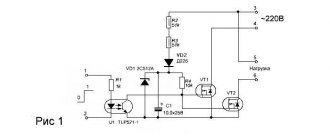
It is implemented thanks to the H-bridge (often called exactly that), which allows you to almost instantly switch the polarity and provide fast reverse. The system is built on transistors and/or microcircuits: the selected ERE guarantee the logical chain along which the keys move. Suitable for brushless models.
According to this diagram, voltage goes from the power source to the bridge. The contacts are switched on in pairs (S1-S4 and S3-S2), due to which current passes through the windings, starting rotation in the desired direction.
With controller
Let's take a closer look at it, because it determines how a stepper motor works and what it is: it is an electronic unit that generates a sequence of signals and sends them to the stator coils. To prevent it from malfunctioning in the event of an emergency (for example, during a short circuit), the drive terminals are equipped with diodes that do not allow reverse pulses to pass through. Makes it possible to implement a variety of modes.
Popular control schemes
We bring to your attention two interesting options:
The key advantage here is noise immunity. Both the direct and inverse signals are connected to their respective poles directly. When implementing it, it is necessary to take care of shielding the signal connector. Suitable when you plan to use a stepper motor with low power: the operating principles will be followed even under high loads.
Another decent solution:
The key feature is the combination of inputs connected to the positive pole. If at the same time a power supply exceeding 9 V is supplied, it will be necessary to supplement the circuit with a current limiting resistor. In general, it is very convenient in that it provides the ability to strictly and accurately set the speed and number of movements during a revolution.
If a logical 1 is applied to one of its D-pins and the others are left at 0, the transistor will open, which will ensure the passage of the signal to the coil. This is a simple way to carry out discrete movement.
We advise you to see in practice what a stepper motor is, the purpose of the device and the principle of operation - try to give it some commands yourself. Taking the latest development as a basis, it is not a problem to make a printed circuit board, to order or even on your own, by soldering the necessary electronic components into it (almost all diodes, transistors, resistors can be removed from used equipment). Control can be carried out from a regular computer.
Smoothing device TL-Smoother
A board that connects the stepper driver and stepper motor, reducing noise and vibration in your 3D printer, reducing the risk of zebra stripe defects.
This small board has eight rectifier diodes that improve the stepper motor waveform, particularly for older, cheaper stepper drivers such as the DRV8825 and A4988. Improving the waveform reduces engine noise by reducing vibration. Since vibrations are reduced, print quality also improves. Just install the board between the driver and the stepper motor, the orientation doesn't matter. For convenience, the kit includes a small 4-wire connector, 20 cm long, to connect the board to the electronics. Cost about 7 $
Zebra stripe or moire defect
How TL-Smoother works
TL-Smoother circuit
The origins of TL smoothing technology back to 2015 when user Schrodinger Z blogged about the jerky movements of the stepper motor and investigated what was happening. As it turns out, the DRV8825 stepper drivers he was using did not generate smooth sine waves for the motors. Upon further inspection, it was discovered that the drivers could not output signals properly at low currents because they were in what is known as a “dead zone.”
The TLs were created to address a specific design flaw in the DRV8825 drivers.
Control Modes
Now let's look at different ways to supply current to the windings and see how the motor shaft rotates as a result.
Wave control or full step control of one winding
This method is described above and is called wave control of one winding. This means that only one winding has electrical current flowing through it. This method is rarely used. Basically, it is used to reduce energy consumption. This method allows you to obtain less than half the motor torque, therefore, the motor load cannot be significant.
This motor will have 4 steps per revolution, which is the nominal number of steps.
Full step control mode
The second and most commonly used method is the full step method. To implement this method, voltage is applied to the windings in pairs. Depending on the method of connecting the windings (series or parallel), the motor will require double the voltage or double the current to operate relative to that required when exciting one winding. In this case, the motor will produce 100% of the rated torque.
Such a motor has 4 steps per full revolution, which is the nominal number of steps for it.
Half-step mode
This is a very interesting way to get double the accuracy of a positioning system without changing anything in the hardware! To implement this method, all pairs of windings can be energized simultaneously, causing the rotor to turn half its normal pitch. This method can also be implemented using one or two windings. Below is how it works.
Single winding mode
Double winding mode
Using this method, the same motor will be able to produce twice the number of steps per revolution, which means double the precision for the positioning system. For example, this motor will give 8 steps per revolution!
Microstepping mode
Microstepping mode is the most commonly used method of controlling stepper motors today. The idea of a microstep is to supply power to the motor windings not with pulses, but with a signal resembling a sine wave in its shape. This method of changing position from one step to the next allows for smoother movement, making stepper motors widely used in applications such as positioning systems in CNC machines. In addition, the jerks of various parts connected to the motor, as well as the shocks of the motor itself, are significantly reduced. In microstepping mode, the stepper motor can rotate as smoothly as conventional DC motors.
The shape of the current flowing through the winding is similar to a sine wave. Digital waveforms may also be used. Here are some examples:
The microstepping method is actually a method of powering the motor, not a method of controlling the windings. Therefore, microstepping can be used in both wave control and full-step control mode. The following demonstrates how this method works:
Although microstepping appears to make the steps larger, this actually does not happen. Trapezoidal gears are often used to improve accuracy. This method is used to ensure smooth movement.
EQUIPMENT TECHNOLOGY DEVELOPMENT
As a rule, the logical signals for controlling the stepper motor are generated by a microcontroller. The resources of modern microcontrollers are quite enough for this even in the most “heavy” mode – microstepping.
To connect stepper motors via low-current logic signals of microcontrollers, signal amplifiers - drivers are needed.
Driver features include:
- ensuring the required current and voltage on the phase windings of the motor;
- winding switching; inclusion;
- shutdown;
- polarity change;
This article is about simple drivers that are sufficient for most applications. There are drivers with much greater capabilities:
- ensuring a rapid increase in current when turned on and a rapid decrease when turned off;
- reducing the current to fix the position of a stopped engine;
- protective functions;
- generation of winding current and voltage for microstepping mode;
- and many others.
The circuitry of such drivers is quite complex, and these functions are not necessary in most applications.
According to the connection diagram, stepper motors are divided into unipolar and bipolar. The drivers for these two engine options are fundamentally different.
- Unipolar stepper motor driver.
- Unipolar stepper motor driver circuit.
- Bipolar stepper motor driver.
- Bipolar stepper motor driver circuit.
- L298N bipolar stepper motor driver.
- Characteristics of the L298N chip in Russian.
- L298N driver connection diagram.
Unipolar stepper motor driver.
Motors with the following winding configurations can operate in unipolar mode.
Let me remind you of the principle of controlling a unipolar stepper motor. Four windings with a common wire connected to one pole of the power source. If the other terminals of the windings are connected in series to the other pole of the source, the motor rotor will rotate.
To switch the windings in this way, only four keys are enough to connect the windings to ground. The switching diagrams for the windings of the two previous engine options look like this.
If you close keys 1, 2, 3, 4 in sequence, the engine rotor will rotate.
Unipolar stepper motor driver circuit.
In practice, switches can be made using bipolar transistors, but it is preferable to use low-threshold MOSFET transistors. I use IRF7341 transistors. These are MOSFET transistors with the following parameters:
- maximum permissible current 4 A;
- maximum voltage 55 V;
- open resistance 0.05 Ohm;
- switching threshold 1 V;
- made in a miniature SO-8 case;
- There are two transistors in the housing.
An extremely convenient option for use in a unipolar stepper motor driver.
- There is no need for key cooling radiators;
- very low voltage drop across an open transistor;
- small sizes;
- only two 8-pin packages for a two-phase stepper motor driver.
It is impossible to create switches with such parameters on bipolar transistors. There are many other options for MOSFET transistors for switches, for example IRF7313 (6 A, 30 V, 0.029 Ohm).
The switch circuit on a MOSFET transistor for one phase looks like this.
The key is controlled directly from the microcontroller by logical levels KMOP or TTL (0 / +5 V). When the control signal is high (+5 V), the switch is open and current flows through the phase winding. The diode bypasses the motor winding in the opposite direction. It is necessary to protect the transistor from self-induction voltage surges when a phase is turned off. To control motors at significant rotation speeds, it is better to use high-frequency diodes, for example, FR207.
Here is a fragment of a diagram for connecting a unipolar stepper motor to a microcontroller.
There is no protection against short circuits in this circuit. Implementing protection significantly complicates the driver. And short circuits in the windings of stepper motors practically never happen. I have not encountered such a phenomenon. And against the backdrop of troubles about a burnt-out expensive engine, replacing the transistor does not look like a problem.
By the way, mechanical jamming of the stepper motor shaft does not cause unacceptable currents in the driver keys and does not require protection.
And this is an image of a controller board for a unipolar stepper motor with a PIC controller from Microchip.
A simple board with an eight-bit PIC18F2520 microcontroller controls:
- two stepper motors with phase current up to 3 A;
- two PWM keys for electromagnets;
- reads the status of 4 sensors;
- exchanges data over the network with the central controller.
This controller is used as part of the stepper motor control system in almost all ROST packaging equipment.
Despite the simplicity of the controller, the following control modes are implemented:
- full-step, one phase per full step;
- full-step, two phases per full step;
- half-step;
- fixing the engine position when stopping.
The advantages of controlling a stepper motor in unipolar mode include:
- simple, cheap, reliable driver.
Disadvantages:
- in unipolar mode the torque is approximately 40% less compared to bipolar mode.
An example of a practical circuit for a simple unipolar stepper motor controller.
An article about connecting a unipolar stepper motor to an Arduino board.
Bipolar stepper motor driver.
Motors with any winding configuration can operate in bipolar mode.
A bipolar motor has one winding for each phase. Usually there are two windings AB and CD. In the first two options, four windings are connected so that two windings are obtained. The windings are connected in turn to the power source in one polarity, then in the other.
The bipolar motor driver must provide complex switching. Each winding:
- connected in direct polarity to the voltage source;
- disconnected from the voltage source;
- connected with opposite polarity.
The switching diagram of one winding of a bipolar motor looks like this.
To provide two polar switchings from one power source, 4 switches are required. When switches 1 and 2 are closed, the winding is connected to the power source in straight polarity. Closing switches 3 and 4 supplies the winding with reverse voltage polarity.
The complexity of the bipolar stepper motor driver is caused not only by the large number of switches (4 keys per winding, 8 keys per motor), but also:
- complex control of the upper keys (1 and 4) from logical signals “tied” to ground;
- problems with through currents when simultaneously opening the keys of one arm (1.3 or 2.4).
Through currents can arise due to different speeds of the lower and upper switches. For example, the lower key has already opened, but the upper key has not had time to close.
Bipolar stepper motor driver circuit.
It is quite difficult to implement a bipolar stepper motor driver circuit using discrete elements. I can show you my circuit that connects a bipolar motor to a unipolar driver. This circuit is used to control bipolar motors from the controller given as an example in the previous chapter.
The scheme is quite simple. The problem of through currents is solved by using 0.22 Ohm resistors in switched circuits. At the moment of commutation of MOSFET transistors, the upper and lower switches are simultaneously open for a short time. These resistors limit the through current. Unfortunately, they also limit the operating current of the motor. Therefore, despite the powerful transistors, a driver according to this circuit can be used for switching currents of no more than 2 A. The circuit does not require diodes to protect against the self-induction emf of the windings, because these diodes are integrated into MOSFET transistors.
It is much more convenient and practical to use integrated bipolar stepper motor drivers. The most common of them is the L298N chip.
L298N bipolar stepper motor driver.
There is practically no description of this microcircuit in Russian. Therefore, I present the parameters of the L298N in sufficient detail, according to the official materials of the manufacturer of this chip - STMicroelectronics (datasheet l298n.pdf).
The L298N is a full bridge driver for driving bidirectional loads up to 2A and 46V.
- The driver is designed to control components with inductive loads such as electromagnets, relays, stepper motors.
- Control signals are TTL compatible levels.
- Two enable inputs make it possible to turn off the load regardless of the input signals of the microcircuit.
- It is possible to connect external current sensors to protect and control the current of each bridge.
- The logic power supply and the L298N load are separated. This allows the load to be supplied with a voltage of a different value than the power supply to the microcircuit.
- The microcircuit has overheating protection at + 70 °C.
The block diagram of the L298N looks like this.
The microcircuit is made in a 15-pin package with the ability to attach a cooling radiator.
L298N pin assignments.
| 1 | Sense A | Resistors are connected between these terminals and the ground - current sensors to monitor the load current. If current control is not used, they are connected to ground. |
| 15 | Sense B | |
| 2 | Out 1 | Bridge A outputs. |
| 3 | Out 2 | |
| 4 | Vs | Load power supply. A low-impedance capacitor of at least 100 nF must be connected between this pin and ground. |
| 5 | In 1 | Bridge control inputs A. TTL compatible levels. |
| 7 | In 2 | |
| 6 | En A | Bridge operation permission inputs. TTL compatible levels. Low signal level prohibits bridge operation. |
| 11 | En B | |
| 8 | GND | General conclusion. |
| 9 | Vss | Power supply for the logical part of the microcircuit (+ 5 V). A low-impedance capacitor of at least 100 nF must be connected between this pin and ground. |
| 10 | In 3 | Bridge control inputs B. TTL compatible levels. |
| 12 | In 4 | |
| 13 | Out 3 | Bridge B outputs. |
| 14 | Out 4 |
Maximum permissible parameters L298N.
| Designation | Parameter | Meaning |
| Vs | Supply voltage | 50 V |
| Vss | Logic supply voltage | 7 V |
| Vi,Ven | Logic input voltage | -0.3…7 V |
| Io | Output current (per channel)
| 3 A 2.5 A 2 A |
| Vsens | Voltage current sensors | -1…2.3 V |
| Ptot | Power dissipation (case temperature 75°C) | 25 W |
| Top | Operating temperature of the crystal | -25…130 °C |
| Tstg | Storage temperature | -40…150 °C |
Parameters for calculating thermal conditions.
| Designation | Parameter | Meaning |
| Tth j-case | Thermal resistance crystal-case | 3 ºC/W |
| Tth j-amb | Thermal resistance crystal-environment | 35 ºC/W |
Electrical characteristics of the L298N driver.
| Designation | Parameter | Meaning |
| Vs | Supply voltage (pin 4) | Vih+2.5 …46 V |
| Vss | Logic power | 4.5…5…7 V |
| Is | Quiescent current consumption (pin 4)
| 13 … 22 mA 50 … 70 mA 4 mA |
| Iss | Quiescent current consumption (pin 9)
| 24 … 36 mA 7 … 12 mA 6 mA |
| Vil | Input voltage low (pins 5, 7, 10, 12, 6, 11) | -0.3…1.5 V |
| Vih | High level input voltage (pins 5, 7, 10, 12, 6, 11) | 2.3…Vss V |
| Iil | Low level input current (pins 5, 7, 10, 12, 6, 11) | -10 µA |
| IIh | High level input current (pins 5, 7, 10, 12, 6, 11) | 30 … 100 µA |
| Vce sat(h) | Upper switch saturation voltage
| 0.95…1.35…1.7 V 2…2.7 V |
| Vce sat(l) | Lower key saturation voltage
| 0.85…1.2…1.6 V 1.7…2.3 V |
| Vce sat | Total voltage drop across public switches
| 1.8 ... 3.2 V 1.8 ... 4.9 V |
| Vsens | Current sensor voltage (pins 1, 15) | -1…2 V |
| Fc | Switching frequency | 25 … 40 kHz |
Connection diagram of a stepper motor to a microcontroller using the L298N driver.
The operation diagram of this circuit in full-step mode looks like this.
If enabling inputs and current sensors are not used, the circuit looks like this.
And here is a fragment of the bipolar stepper motor controller circuit.
In terms of functions, this is an analogue of the controller described in the chapter on unipolar motors, only for bipolar ones. It is also assembled on a Microchip PIC controller and controls two bipolar stepper motors with a phase current of up to 2 A. The functionality and motor control modes are the same.
The advantages of controlling a stepper motor in bipolar mode include:
- the torque is approximately 40% greater compared to unipolar mode.
- You can connect stepper motors with any winding configuration.
Disadvantages:
- complex driver.
Another stepper motor controller circuit.
Support the project
0
Author of the publication
offline 15 hours
Edward
236
Comments: 1790Publications: 183Registration: 13-12-2015