The unpretentiousness and relative physical stability of posistors allows them to be used as a sensor for self-stabilizing systems, as well as to implement overload protection. The principle of operation of these elements is that their resistance increases when heated (unlike thermistors, where it decreases). Accordingly, when checking posistors for performance with a tester or multimeter, it is necessary to take into account temperature correlation.
PTC posistor C831
Considering the inscription “RTS”, we can state that this element is a posistor “C831”. Having generated a request in a search engine (for example, “RTS C831 datasheet”), we find the specification (datasheet). From it we learn the name (B59831-C135-A70) and series (B598*1) of the part, as well as the main parameters (see Fig. 3) and purpose. The latter indicates that the element can play the role of a self-restoring fuse, protecting the circuit from short-circuit protection and overcurrent.
Where is it used (scope of application)
Thermistors are actively used in various fields closely related to electronics.
They are especially important when implementing processes that depend on the correct temperature settings. This approach is relevant for computer technologies, information transmission devices, high-precision industrial equipment, etc.
A common way to use thermistors is to limit the currents that arise during the startup of devices.
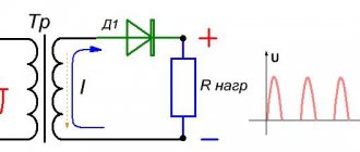
When voltage is applied to the power supply, the capacitor quickly gains capacity, which leads to increased current flow. If you do not limit this parameter, there is a high risk of damage (breakdown) to the diode bridge.
To protect an expensive component, a thermistor is used - an element that limits the current in case of sudden heating. After the mode is normalized, the temperature drops to a safe level and the thermistor resistance returns to its original level.
What is a resistor
The simplest definition looks like this: a resistor is an element of an electrical circuit that resists the current flowing through it. The name of the element comes from the Latin word “resisto” - “I resist”; radio amateurs often call this part “resistance”.
Let's look at what resistors are and what resistors are needed for. Answers to these questions imply familiarity with the physical meaning of the basic concepts of electrical engineering.
To explain the principle of operation of a resistor, you can use an analogy with water pipes. If you somehow impede the flow of water in a pipe (for example, by reducing its diameter), an increase in internal pressure will occur. By removing the obstacle, we reduce the pressure. In electrical engineering, this pressure corresponds to voltage - by making it difficult for the flow of electric current, we increase the voltage in the circuit, reducing the resistance, we also lower the voltage.
By changing the diameter of the pipe, you can change the speed of water flow; in electrical circuits, by changing the resistance, you can regulate the current strength. The amount of resistance is inversely proportional to the conductivity of the element.
The properties of resistive elements can be used for the following purposes:
- converting current into voltage and vice versa;
- limiting the flowing current to obtain its specified value;
- creation of voltage dividers (for example, in measuring instruments);
- solving other special problems (for example, reducing radio interference).
You can use the following example to explain what a resistor is and why it is needed. The familiar LED glows at low current, but its own resistance is so low that if the LED is placed directly in the circuit, then even at a voltage of 5 V the current flowing through it will exceed the permissible parameters of the part. From such a load the LED will immediately fail. Therefore, a resistor is included in the circuit, the purpose of which in this case is to limit the current to a given value.
Watch this video on YouTube
All resistive elements belong to passive components of electrical circuits; unlike active ones, they do not release energy into the system, but only consume it.
Having understood what resistors are, it is necessary to consider their types, designation and markings.
How to determine the health of SMD resistors
SMD resistors are surface-mount components, the main difference of which is the absence of holes in the board. The components are installed on the current-carrying contacts of the printed circuit board. The advantage of SMD components is their small dimensions , which makes it possible to reduce the weight and size of printed circuit boards.
Testing SMD resistors with a multimeter becomes more difficult due to the small size of the components and their labels. The resistance value on SMD components is indicated as a code in special tables, for example, the designation 100 or 10R0 corresponds to 10 Ohms, 102 indicates 1 kOhm. Four-digit designations may occur, for example 7920, where 792 is the value and 0 is the multiplier, which corresponds to 792 ohms.
A surface mount resistor can be checked with a multimeter by completely desoldering it from the circuit, leaving one end soldered on the board and lifting the other with tweezers. After this, a measurement is carried out.
Problems with temperature control on your unit may indicate problems with the thermostat, the resistance of which can be checked using a multimeter.
Read also: Connecting the connector to the Internet cable
I connected and set up this multimeter according to the instructions and turned the knob to the lowest ohms range. The working thermostat shows a resistance of zero or close to zero. This thermostat has a reading of 1.4, which means it is working. If there are no readings on the device, then the thermostat is faulty and needs to be replaced.
A posistor is one of the parts of the system that is responsible for demagnetization. With high magnetization, the TV image is distorted or stripes appear. Their appearance means that the device has failed. It is necessary to check its functionality. If necessary, the posistor is repaired or replaced.
How to connect, diagrams
Let's look at the basic connection diagrams for a PTC resistor, depending on the purpose for which it is used. Most often, the elements are connected in series, but sometimes they can also be connected in parallel, for example, to a start relay.
Scheme for thermal fire detectors:
PTC as fuse:
Examples of other circuits for posistors:
As a temperature sensor, temperature compensation
Below is the principle of temperature compensation: when biasing the transistor, R of the posistor is used. If the first one overheats, the t° on the second one also increases, and when the value overcomes the Curie point, the TR switches to the powerful resistance mode, the circuit shifts, and the transistor turns off.
If the PTC acts as an overheat detector when temperature compensation is required, the device does not change the input resistance like an NTC thermistor, given the series connection to the input circuit. This is excellent for variants of the latter that require the described nuance: for impulse lines, regional amplifiers, measuring devices.
Several posistors in the circuit
Two or more PTCs can serve several active segments of the comparator. Below is a diagram for sequentially connecting an increased number of TRs: when at least one of the microcircuits is detected by the comparator, a sharp value of temperature resistance is demonstrated. Such a circuit will allow you to easily change the number of PTCs or measure t° on the entire basic circuit.
Engine overheat protection
PTC is used to monitor overheating of electric motors, transformer windings, bearing structures, and power transistors. Below is an example of a PTC that detects excessive heating of the motor, which triggers the relay to turn it off.
Directly with a posistor, circuits with small regular currents can be blocked, but if they are large and constant, a relay or thyristor can be connected to the line.
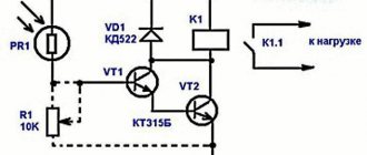
Control Component
PTC, as an electronic component of current control, is shown in the simplest solution below:
When the set temperature is exceeded, the diode lights up. If the current limit value is violated, the thermistor will react and immediately implement protection.
The delay option can be implemented through the dynamic properties of the TP, there are two methods: connecting in parallel or in series with a relay. It is also possible to control starting currents with a posistor, for example, on switching power supplies, which, as a rule, have a significant value at the first start.
PTC can be used instead of NTC or a simple resistor as an inrush current limiter. The part is heated by current overloads when a relay or thyristor fails and it is triggered at high resistance, the flow of current is blocked instantly.
In addition to the above, it is practical to use PTC for a motor starting circuit as a contactless starter, for example, for a compressor for refrigerators, air conditioners and the like.
On Arduino
A programmable base in the form of an Arduino controller is used for various homemade products and mini-robots.
In this case, it is necessary to connect the PTC to the specified platform to read the indicators, an LCD display showing them will also be included there.
Description of the example (with a thermistor rating when it is hot at 10 kOhm):
- there is a ceramic heating part of the soldering iron with low-resistance PTC, how to connect it to Arduino;
- This is the solution. The order of the circuit is: “ground - PTC - resistor of about 10 kOhm - +5V (positive contact). That is, from the PTC connection with the resistor, pull the wire to the Arduino input. If the latter is analog, then with cold PTC there is about 0, with hot 500 Ohms, if digital, then LOW and HIGH. If you need to configure exactly when to turn it on. HIGH, experiment with a resistor - the higher its value, the later (with a hotter TR) this value turns on.
Below is the same thing in slightly different words. For a basic assembly, let's take a circuit board, 3 wires, PTC, a 10 kOhm resistor (this is the main resistance of the circuit). The output of the latter is connected to the PTC pin, to which there is also a wire connected to, in our case, the analog pin A0 of the Arduino. That is, one PTC contact is to 5V, and the second, connected to the leg of the 10 kOhm resistor, is to A0. The remaining leg of the latter goes to the ground pin. The diagram below shows the order clearly.
You can learn more about working with various components on some online simulator.
PTC resistors (PTC resistors) as a type of thermistors
For electronics, temperature is one of the factors that requires constant monitoring, since abnormal heating indicates a change in current parameters and unsafe phenomena (overheating up to burnout).
On instrument boards, the most basic standard elements, radio components that measure t°, monitoring its values and protecting the circuit, are thermistors. The parts react in a special way: their resistance (R) changes at different temperatures, and accordingly, currents of a certain power are passed or not passed, this is how the protection of the microcircuit and devices is realized.
Thermal resistors (TR) are semiconductor electronic parts made from alloys with a high thermal transformation coefficient.
Determining serviceability by appearance
Unlike other radio components (for example, such as a transistor or diode), a failed RTS resistor can often be identified by its appearance. This is due to the fact that due to exceeding the permissible dissipation power, the integrity of the housing is compromised. Having found a posistor on the board with such a deviation from the norm, you can safely unsolder it and start looking for a replacement, without bothering yourself with the testing procedure with a multimeter.
If the external examination does not produce results, we proceed to testing.
PTC resistors (PTC resistors) as a type of thermistors
For electronics, temperature is one of the factors that requires constant monitoring, since abnormal heating indicates a change in current parameters and unsafe phenomena (overheating up to burnout).
On instrument boards, the most basic standard elements, radio components that measure t°, monitoring its values and protecting the circuit, are thermistors. The parts react in a special way: their resistance (R) changes at different temperatures, and accordingly, currents of a certain power are passed or not passed, this is how the protection of the microcircuit and devices is realized.
Thermal resistors (TR) are semiconductor electronic parts made from alloys with a high thermal transformation coefficient.
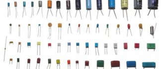
Types of resistors
A resistor is an electronic component that has a constant or variable resistance value. Externally, the resistor is a cylinder made of a special material, which determines its resistance. Some resistors are made by winding very thin wire onto a dielectric base. There are two terminals at the ends of the cylinder, which are used for soldering the radio component to the board. Resistors can be divided into two groups:
- Constant - the resistance value is set during production and cannot be changed.
- Variables, or trimmers - the maximum resistance value is unchanged, but they have a third output. This pin is connected to a mechanical assembly that moves a slider along the surface of the resistor. By moving this slider, you can change the resistance between the fixed and moving contacts from zero to its maximum value.
How PTC works from a physico-chemical point of view
A PTC thermistor increases its resistance (denoted in diagrams by R, in Ohms) as t° increases; The NTC thermistor has the same algorithm, but vice versa: as the first value increases, the second value decreases.
The main feature of the thermistor is the maximum sensitivity R of the material to changes in t°. If there is no heating, then the atoms are arranged evenly, arranged in long lines. As heat increases, the number of charge transporters becomes larger, and the more, the better the conductivity.
The t°/R curve is nonlinear; the properties are most pronounced at −90…+130° C.
TR properties are created by comparing the t° mode with the characteristics of the alloys used in the part, which are semiconductors. They use compounds that are extremely temperature sensitive.
When current passes, an electric field appears, pushing the electrons hitting the atoms, so they are slowed down. At high temperatures, the movement of atoms is more intense, the initial particle interacts faster, creating additional resistance. After cooling, the valence levels of electrons will become low, go into a quiet state, the particles will move less, and will no longer increase the Ohm number.
Deciphering the specifications of a specific model
These were the main parameters of the series, now let’s look at the specification for C831 (see Fig. 5).
B598 Series Model Specification*1
Brief transcript:
The current value for normal operation, for our part is almost half an ampere, namely 470 mA (0.47 A). This parameter indicates the current at which the resistance value begins to change significantly upward. That is, when a current of 970 mA flows through C831, the “protection” of the device is triggered. It should be noted that this parameter is associated with the temperature transition point, since the passing current leads to heating of the element. The maximum permissible current value for switching to the “protective” mode, for C831 it is 7 A
Please note that the column indicates the maximum voltage, therefore, you can calculate the permissible amount of power dissipation, exceeding which will most likely lead to destruction of the part. The response time for the C831 at a voltage of 265 volts and a current of 7 amperes will be less than 8 seconds. The amount of residual current required to maintain the protective mode of the radio component in question is 0.02 A. It follows from this that a power of 5.3 W (Ir x Vmax) is required to maintain the triggered state. Device resistance at a temperature of 25°C (3.7 Ohm for our model)
Note that by measuring this parameter with a multimeter, checking the posistor for serviceability begins. The minimum resistance value for the C831 model is 2.6 Ohms. To complete the picture, we will once again present a graph of the temperature dependence, where the nominal and minimum values of R will be marked (see Fig. 6).
Figure 6. Temperature correlation plot for B59831, RN and Rmin values marked in red
Read also: How to set the ignition on Java to 6 volts
Please note that at the initial stage of heating the radio component, its parameter R decreases slightly, that is, in a certain temperature range, our model begins to exhibit NTS properties. This feature, to one degree or another, is characteristic of all posistors.
- Full model name (we have B59831-C135-A70), this information may be useful for searching for analogues.
Now, knowing the specification, you can move on to testing for functionality.
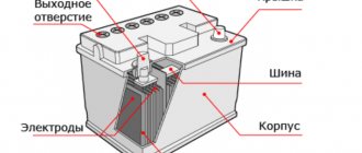
A posistor: how to check for serviceability?
The picture tubes of most TVs use demagnetization systems that have a posistor built into them. Owners who want to carry out repairs themselves need to know how to check such a chain if it fails. The element has physical properties that can be checked with a regular ohmmeter.
Element properties
It is worth studying what a posistor is, how to check it in a circuit - it will become clear later. This element is capable of changing properties depending on temperature. Its physical value resistance is measured. At room temperature, the ohmmeter readings show units or tens of ohms.
When heated in operation, the resistance begins to change upward. The ohmmeter values already show hundreds of kilo-ohms, which indicates the normal state of the element - such a posistor is working. How to check if there is a suspicion of a faulty circuit? Below are ways to resolve this issue.
Due to their properties, posistors are widely used in microelectronics for various purposes:
- Protection of power circuits. With increased current consumption, the element heats up and increases the resistance to a maximum when a current cutoff is observed.
- In heating circuits. Thanks to posistors, an automatic heating control system is implemented.
- In thermal sensor circuits.
Internal structure of the element
A resistor changes its resistance with heating, just like a posistor. How to check the first element? This one is simple. The resistor values fluctuate within insignificant limits. A posistor is capable of completely blocking the current passing through it, just like a themistor. Only the latter exhibits an inverse dependence on temperature.
To know how to check the serviceability of a posistor, you should determine its main operating characteristics. These include:
- nominal resistance at normal ambient temperature (usually 20-25 degrees);
- The switching resistance is determined at the point of the resistance versus temperature characteristic when the first parameter increases by 2 times compared to the nominal value;
- the maximum voltage that the element can withstand without failure;
- current load values: rated, switching, maximum possible and stalling; For testing, these parameters are important only if the posistor will be used in high-precision circuits.
How to check with a multimeter
An important issue when operating thermistors is knowledge of the principles for testing them. When assessing serviceability, you need to understand that there are two types of thermistors - with positive and negative temperature coefficients (this was mentioned above). Consequently, the resistance of the part decreases or decreases with increasing temperature.
Taking into account this fact, to check the thermistor you only need two elements - a heating soldering iron and a multimeter.
Algorithm of actions:
- Switching the device to resistance measurement mode.
- Connecting the probes to the thermistor terminals (location does not matter).
- Fixing the resistance on paper and bringing the heated soldering iron to the part.
- Resistance control (it rises or falls depending on the type of thermistor).
- If the resistance decreases or increases, the semiconductor is working correctly.
For example, you can use an NTC thermistor type MF 72. In normal mode, it shows a resistance of 6.9 ohms at normal temperature.
After bringing the soldering iron close to the product, the situation changed - the resistance went downward and stopped at two ohms. Based on this check, we can conclude that the thermistor is working properly.
If the resistance changes sharply or does not move at all, we can talk about the failure of the part.
It is worth considering that such a test is very rough. For accurate control, you need to check the temperature and resistance of the thermistor, and then compare the data with the official parameters.
Dependence of resistance and temperature
The resistance of ideal semiconductors (the number of holes and charge carriers are the same) depending on temperature can be represented by the following formula
R(T) = A exp(b/T)
where A, b are constants depending on the properties of the material and geometric dimensions.
However, the complex composition and non-ideal charge distribution in a thermistor semiconductor does not allow direct use of the theoretical dependence and requires an empirical approach. For NTC thermistors, the Steinhart and Hart approximation is used
1/T = a+b(lnR)+c(lnR)3
where T is temperature in K;
R – resistance in Ohm;
a,b,c – thermistor constants determined during calibration at three temperature points spaced from each other by at least 10 C.
Glass thermistor.
A typical 10 kOhm thermistor has coefficients in the range of 0-100 C close to the following values:
- a = 1.03 10-3
- b = 2.93 10-4
- c = 1.57 10-7
Disc thermistors can be interchangeable, i.e. all sensors of a certain type will have the same characteristic within the tolerance specified by the manufacturer. The best possible tolerance is generally ±0.05 C over the range 0 to 70 C. Bead thermistors are not interchangeable and require individual calibration.
Thermistors can be calibrated in liquid thermostats. It is necessary to seal the thermistors by immersing them in glass test tubes. Usually, for calibration and calculation of constants, the thermistor is compared with a standard platinum thermometer.
In the range from 0 to 100 C, comparison is carried out at points with an interval of 20 C. The interpolation error usually does not exceed 1–5 mK when using the modified Steinhart and Hart equation:
1/T = a+b(lnR)+c(lnR)2 + d(lnR)3
Reference points can also be used: the triple point of water (0.01 C), the melting point of gallium (29.7646 C), phase transition points of eutectics and organic materials.
To calibrate several thermistors, they can be connected in series so that the same current passes through them
When calibrating and using thermistors, it is important to take into account the heating effect of the measuring current. For a 10 kOhm thermistor, it is recommended to select currents from 10 μA (error 0.1 mK) to 100 μA (error 10 mK)
To begin with, let's define this type of radio components as thermistors (or, as they are also called, thermistors). They are a semiconductor element whose resistance changes depending on temperature. This dependency could be:
- Direct (the higher the temperature, the higher the resistance) is the PTC type (from the English Positive Temperature Coefficient, that is, positive/positive temperature coefficient). An alternative name is “posistors”.
- Reverse (resistance increases as temperature decreases and vice versa) is the NTC type (from the English Negative Temperature Coefficient, that is, negative/negative temperature coefficient).
Thermistors are often divided according to operating temperature ranges:
- Low temperature (below 170 K);
- Medium temperature (170-510 K);
- High temperature (over 510 K).
The thermistor designation is shown in the figure below.
Thermistor device.
Calibration tables of resistance thermometers
Calibration tables are a summary grid from which you can easily determine at what temperature the thermometer will have a certain resistance. Such tables help instrumentation and automation workers estimate the value of the measured temperature based on a certain resistance value.
Within this table there are special vehicle designations. You can see them in the top line. The number means the resistance value of the sensor at 0°C, and the letter means the metal from which it is made.
To designate metal use:
- P or Pt – platinum;
- M – copper;
- N – nickel.
For example, 50M is a copper TC with a resistance of 50 Ohms at 0 °C.
Below is a fragment of the thermometer calibration table.
| 50M (Ohm) | 100M (Ohm) | 50P (Ohm) | 100P (Ohm) | 500P (Ohm) | |
| -50 °C | 39.3 | 78.6 | 40.01 | 80.01 | 401.57 |
| 0 °C | 50 | 100 | 50 | 100 | 500 |
| 50 °C | 60.7 | 121.4 | 59.7 | 119.4 | 1193.95 |
| 100 °C | 71.4 | 142.8 | 69.25 | 138.5 | 1385 |
| 150 °C | 82.1 | 164.2 | 78.66 | 157.31 | 1573.15 |
Graphic designation
In UGO thermistor diagrams, the thermistors may differ slightly, but the main sign of thermal resistance is the symbol t next to the rectangle symbolizing the resistor. Without this symbol, it is impossible to determine what the resistance depends on - for example, varistors have similar UGO (resistance is determined by the applied voltage) and other elements.
Sometimes an additional designation is applied to the UGO, which determines the category of the thermistor:
- NTC for elements with negative TCS;
- PTC for posistors.
This characteristic is sometimes indicated by arrows:
- unidirectional for PTC;
- multi-directional for NTC.
The letter designation can be different - R, RK, TH, etc.
How to fix it yourself
Finding the device is not difficult; it is located behind the back cover, next to the plug, which includes a demagnetization loop.
If the reason is magnetization of the device, it must be demagnetized. To do this, the device is unsoldered from the TV and connected to a demagnetization system.
But in most cases, damage to the device requires its replacement. You need to unsolder the old one and solder in a new one with similar characteristics. If we select the wrong device, it will not work.
More about the scope
With proper configuration and installation of the thermistor, it can become an element for checking the temperature conditions outdoors or indoors. You can use it to track any changes. Of course, we are not talking about such accurate measurements as is required in production areas. A step of one degree will be enough. The part is also often used in the engine protection system against overheating. In this case, the specialist connects it to the relay. If a heating hazard occurs that violates all acceptable safety precautions, the engine is switched off. If you have experience, you can include a thermistor in the on-board PC system. This allows you to track indicators on the monitor, which is a very convenient solution in practice.
All thermistors are produced in housings with protective properties, which eliminates the influence of moisture on them. This has a positive effect on the service life of the element. If a specialist selects the thermistor correctly, he can count on long-term use of the element and the equipment in which it will be installed.
Decoding the main characteristics
Let's briefly look at the data shown in the table in Figure 3 (for convenience, the lines are numbered).
Figure 3. Table with the main characteristics of the B598 series*1
Short description:
- a value characterizing the maximum level of operating voltage when the device is heated to 60°C, in this case it corresponds to 265 V. Considering that there is no definition of DC/AC, it can be stated that the element operates with both alternating and direct voltage.
- The nominal level, that is, the voltage in normal operation, is 230 volts.
- The estimated number of element operation cycles guaranteed by the manufacturer, in our case there are 100.
- A value describing the value of the reference temperature, after which a significant increase in the resistance level occurs. For clarity, we present a graph (see Fig. 4) of temperature correlation.
Rice. 4. Dependence of resistance on temperature, the temperature transition point (reference temperature) for C831 is highlighted in red
As can be seen in the graph, R increases sharply in the range from 130°C to 170°C, respectively, the reference temperature will be 130°C.
- Compliance with the nominal R value (that is, tolerance) is indicated as a percentage, namely 25%.
- Operating temperature range for minimum (-40°C to 125°C) and maximum (0-60°C) voltage.
How does it work
A thermistor is a semiconductor element with varying characteristics (resistance) depending on temperature. The product was invented in 1930, and the famous scientist Samuel Ruben is considered its creator. Since its appearance, the thermistor has become widespread in radio electronics and is successfully used in many related fields.
The part is manufactured using materials with a high temperature coefficient (TC). They are based on special semiconductors whose characteristics are superior to the purest metals and their alloys.
When preparing the main resistive element, oxides of certain metals, halides and chalcogenides are used. Copper, nickel, manganese, cobalt, germanium, silicon and other substances are used for manufacturing. During the manufacturing process, the semiconductor will have to be shaped differently. On sale you can find thermistors in the form of thin tubes, large washers, thin plates or small round elements. Some parts have dimensions of several microns.
A thermistor is a resistor with a high temperature coefficient of resistance (TCR). When the temperature of the thermistor's conductive material changes, its electrical resistance changes significantly. Thermistors can be either positive or negative TCS. Thermistors with a positive TCS are called PTC thermistors or posistors, and those with a negative TCS are called NTC thermistors. When a PTC thermistor (posistor) heats up, its resistance increases. When an NTC thermistor heats up, its resistance decreases.
Basic parameters and characteristics of thermistors with negative TCS.
The resistance of the posistor corresponds to the nominal Rн specified in the reference documentation, usually at a temperature of 25 degrees. Celsius, less often at 20. At the beginning of heating of the PTC thermistor, its resistance will decrease slightly to a certain minimum value Rmin. With further heating to a certain temperature Tref, the resistance of the posistor will increase slightly.
Further heating in the temperature range from Tref to the maximum permissible value entails a rapid increase in resistance. In this case, the difference in resistance can reach several orders of magnitude.
Types of thermistors and their testing
Separately, we need to talk about what a posistor and thermistor are, and how to check them with a multimeter.
A thermistor is a radio component made from semiconductor materials. The resistance of these elements is not constant and depends on temperature. Thermistors are divided into two groups:
- A thermistor is an element with a negative temperature coefficient of resistance. This means that when heated, its resistance decreases.
- A posistor has a positive temperature coefficient of resistance, that is, when heated, its resistance increases.
As with conventional resistors, before starting the test it is necessary to find out the nominal value of the sample being tested. This can be done using reference data based on the thermistor markings.
But there is one peculiarity, since the resistance depends on temperature, reference books can give a whole table of temperatures and the corresponding resistances. In this case, you need to focus on the resistance value at a temperature close to the ambient temperature.
If the data indicates only one resistance value, then, as a rule, it corresponds to a temperature of 25 degrees.
In practice, it is difficult to accurately maintain a certain temperature, so the resistance of a working thermistor will differ slightly from the nominal data, and this must be taken into account when measuring.
Let's take a step-by-step look at how to check a posistor with a multimeter, then checking the thermistor will not cause you any difficulties. In addition to the tester, you will need a heat source, such as a soldering iron or hair dryer. A working posistor must pass all three tests:
- We measure the resistance value of the posistor in an unheated state. If the resistance corresponds to the nominal value, then you can continue testing. Otherwise the item is defective.
- During this test step we will need to heat the element, so plan in advance how you will take measurements, for example, install clamps on the probes. After you have connected the tester to the posistor, bring a heated soldering iron to it. As it heats up, the resistance value should increase; if the device readings do not change, the radio component is damaged.
- Stop heating the posistor and wait until it cools down to room temperature. Measure its resistance, it should return to the original value measured in the first point.
Checking the thermistor is carried out in the same way as checking the posistor, with the only difference being that in the second point, when heated, the resistance value should decrease.
PTC
There are also PTC thermistors whose TCS is positive.
What does this mean?
When a part heats up, its internal resistance increases. Such products could often be found in old color television receivers with picture tubes.
Today, two types of RTS parts can be distinguished - with two or three terminals.
For products with three contacts, the main difference is that they have two positrons in the form of “pills” enclosed in one housing.
Externally, these two elements look almost identical. But this is a misleading impression.
They differ in both size and resistance.
In the first case, the operating range is from 1.4 to 3.7 kOhm, and in the second option - 17–25 Ohms.
Double-lead parts are most often produced with the addition of silicon (Si). They look like a small tablet with a pair of pins.
RTC elements are most often used to protect power equipment from overloads and overheating. And to maintain the correct temperature within safely stable ranges.
What pharmacist malfunctions can you encounter?
You can determine if there is a fault in an element by seeing a distorted image on the screen. This means that the element is highly magnetized. This problem can be resolved by connecting the grid in series with the device. The mesh is the outer loop that covers the inside surface of the screen.
Read also: Why the soldering iron does not heat up
A posistor is often soldered to the screen. Therefore, it becomes very difficult to check it without disconnecting it from the TV. To take measurements, you need to unsolder at least one part of the device from the grid. But the best solution would be to completely remove the device from the system.
You can heat the posistor with a simple hairdryer. To check the functionality of the device without heating it externally, you need to assemble an electrical circuit. This will help determine the device type. The instructions should state at what voltage the element operates and what temperature it can withstand.
You can determine if the device is working properly by heating it with a hairdryer. If an increase in resistance is noticed, then the element is working. But this method of verification has a drawback - the results may be erroneous. The problem is that the resistance of the parts of the assembled circuit can change over time, and therefore they begin to work unstable.
Another way to determine a posistor malfunction is image distortion. It may ripple, or extra stripes may appear. You can determine the performance of the element using a multimeter. It is recommended that the posistor be cold, since resistance increases when heated.
Another problem is that the contacts have fallen off. With constant heating of the posistor, they begin to wear out, and as a result they fall off. The contacts may look normal on the outside but not work. You can determine their performance using an ohmmeter.
If the posistor is broken or shorted, the fuse will blow the first time you turn on the TV. If there is no short circuit in the network, you need to disconnect the posistor and check its functionality.
Attention! It is possible that it is not the posistor itself that is damaged, but the element responsible for cooling it. We are checking.
What are PTC thermistors (posistors), how do they differ from thermistors (NTC)
There are 2 types of thermal resistors, the operating principle is similar, only the direction of the temp is different. coefficient (TCS):
- posistors - positive. Resistance follows temperature. They are also often called positive TCS thermistors or PTC thermistors;
- thermistors (NTC) - negative. The Ohm number moves against the direction of t° (as it increases, it falls). Often both are called by this term, but if there is no specification, then this word by default means exactly the element with Negative temp. Coef, that is, a distinction is made between thermistors/posistors.
Often PTC (posistors) and thermistors (NTC) are similar in appearance, so you need to read the specification and the inscriptions on the cases:
Designation on the diagrams:
Schematic drawings for different spare parts may be similar, so you need to read them carefully:
TP icons may differ slightly, but t° is necessarily present in them; posistors almost always have alphanumeric designations R1, TH1 or RK1. Thus, you can unmistakably recognize these elements in the drawings.
For PTC, two arrows point up; “−” near t° is set for NTC, since it has a negative coefficient.
Visual explanation of the work
The principle of operation is based on the interconnected change of 2 parameters: the temperature of the external environment or the element itself and its resistance (number of Ohms).
SMD thermistor:
If you take any thermal resistor and use a multimeter to measure the resistance on it at normal room temperature and when it is cooled/heated, the number of Ohms will be different. In PTC, as the temperature increases, the R value will increase.
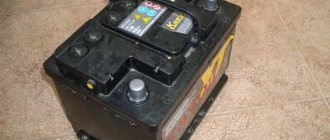
Element in the cooler circuit
If the back of the refrigerator - the radiator - does not heat up, then for self-repair you need to familiarize yourself with how to check the posistor. Two types of starters can be used in the refrigerator: with posistors and with electromagnetic relays. The former spend part of the energy on heat loss in the resistance of the element, the latter are less reliable, but do not heat up.
Most posistors in refrigerators should have a resistance of about 20–30 ohms. When heated, there may be several kiloohms. If the values significantly exceed those given, the element must be replaced. It is important to let the posistor cool to room temperature before taking measurements.
Date: 09.12.2015 //
Thermistors are divided into two types: posistors and thermistors . They all change their resistance depending on their temperature. For posistors, the resistance increases depending on temperature, while for thermistors, on the contrary, it decreases . Thermistors find their application in many components of various equipment and equipment, ranging from temperature sensors to inrush current limiters in energy-saving lamps, power supplies or motors.