History of invention
In 1873, the English scientist Frederick Guthrie developed the operating principle of directly heated vacuum tube diodes.
A year later, in Germany, physicist Karl Ferdinand Braun suggested similar properties in solid-state materials and invented a point rectifier. In early 1904, John Fleming created the first complete tube diode. He used copper oxide as the material for its manufacture. Diodes have begun to be widely used in radio frequency detectors. The study of semiconductors led to the invention of the crystal detector in 1906 by Greenleaf Witter Pickard.
In the mid-30s of the 20th century, the main research of physicists was aimed at studying the phenomena occurring at the metal-semiconductor contact boundary. Their result was the production of a silicon ingot with two types of conductivity. While studying it, in 1939, the American scientist Russell Ohl discovered a phenomenon later called the pn transition. He found that depending on the impurities existing at the interface of two semiconductors, the reducibility changes. In the early 50s, Bell Telephone Labs engineers developed planar diodes, and five years later, germanium-based diodes with a transition of less than 3 cm appeared in the USSR.
The inventor of the rectifier bridge circuit is considered to be an electrical engineer from Poland, Karol Pollak. Later, the results of Leo Graetz’s research were published in the journal Elektronische Zeitung, so in the literature one can also find another name for a diode bridge - circuit or Graetz bridge.
Operating principle
What is a welding rectifier
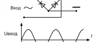
The simplest rectifier circuit consists of a diode connected between the power source and the load. The operation of the circuit is based on the property of the diode to conduct current in one direction and not pass it in the opposite direction. The output produces a voltage consisting of only positive half-waves, and, accordingly, a rectified current. If the diode is connected in the opposite direction, the signal will consist of negative half-waves.
The simplest rectification circuit
Half-wave rectification
After rectification, the current flows in one direction, alternating a positive half-wave with zero voltage values. The quantitative indicator of this changing voltage will be equal to the equivalent constant voltage of 0.318 U, where U is the maximum value of the input sinusoidal signal.
Disadvantages of the scheme:
- Since the load voltage is only present during the positive half of the cycle (50% of the input signal), this results in a low average DC current delivered to the load;
Important! Sometimes this feature is used in circuits for limiting the power of resistive loads, for example, with two-level lighting control.
- Changing the rectified output creates a waveform that has a lot of ripple, which is undesirable.
Sometimes a capacitor is used to smooth out pulsations. But there are restrictions on the cost and size of the capacitors used. In practice, half-wave rectification is rarely used and only for powering low-power circuits.
Full wave rectification
Almost all circuits require a steady and smooth DC voltage. One way to achieve this is to use every half cycle of the input voltage.
Full-wave rectifiers have fundamental advantages over their half-wave counterparts:
- the average output voltage is higher than for a half-wave signal;
- The output of a full-wave rectifier has much less ripple.
Full-wave rectification circuit with transformer
The circuit uses two diodes, one for each half of the cycle. The other main component is the transformer, the secondary winding of which is divided into two halves with a common central connection. This configuration causes each diode to conduct its half-wave current when its anode terminal is positive relative to the center point of the transformer, and produces an output across the load during both half-cycles.
As a result, the current flowing through the load flows in the same direction for both half cycles, and the output voltage represents the sum frequency of the two signals. This type of circuit is known as two-phase.
The average output voltage through the load resistor is now twice as large and equal to 0.637 U, where U is the maximum input voltage, or 0.9 U of the rms value.
Important! To obtain a different output voltage, different transformation ratios can be used.
The main disadvantage of the circuit is that it requires a large transformer for a given output power with two separate but identical secondary windings, which makes it expensive compared to a full-wave bridge.
Bridge circuit
This type of single-phase rectifier uses four individual diodes connected in a closed-loop bridge configuration to produce the desired output.
The main advantage of the bridge circuit is that a special main shut-off transformer is not required. A single secondary winding is connected to one side of the diode bridge, and the load is connected to the other.
Diode bridge circuit
Features of the diode bridge:
- During the positive half-cycle, one pair of diodes in the opposite arms of the bridge is open, the other is locked. The current signal passes through the load unidirectionally;
- When a negative half-cycle occurs, another pair of diodes opens, and the first pair closes. At the output, the current flows in a similar direction;
- The output voltage is constant and is 0.637 of the maximum amplitude value;
Important! In reality, there is also some voltage drop across the diodes themselves (2 x 0.7 = 1.4V for silicon). But this drawback is significant only in low voltage circuits.
- The ripple frequency of the rectified signal is twice the supply frequency. For 50 Hz the output is 100 Hz.
In practical implementation of these circuits, four separate diodes can be used, but ready-made bridge rectifier components are also available for sale in different voltages and currents. The beveled corner indicates that the nearest output terminal is positive (+), the one opposite is negative (-), and the other two terminals are for AC input voltage from the transformer secondary winding.
Diode bridge
Smoothing capacitor
It is possible to improve the average DC output voltage of the rectifier while adding smoothness to the signal by using smoothing capacitors that are connected in parallel with the load.
The capacitor is charged to the peak voltage of the output pulse. But when the voltage drops to zero, it cannot discharge instantly due to the time constant of the RC circuit. The capacitor only discharges to a certain point, maintaining the voltage across the load until it charges again at the next peak. Thus, the voltage changes are small, but the smoothing can be further increased by increasing the capacitor value.
Diode bridge circuit with capacitor
Typically, for DC power circuits, an aluminum or electrolytic type capacitor with a capacity of 100 μF or more is used.
When choosing a smoothing capacitor, the following are taken into account:
- Operating voltage of the element, which must be higher than the output value of the rectifier without load;
- Capacitance that determines the amount of ripple. If it is too low, it will have little effect on the output signal.
Important! With a large capacitance and low load current, an almost pure constant signal can be obtained.
The maximum ripple voltage in the presence of a smoothing capacitor depends on the frequency and load current and is determined by the formula:
U = I / fx C, where f is the frequency of the input voltage.
Three-phase rectification circuit
The advantage of the bridge rectifier device is its easy transformation into a three-phase version. The wire of each phase is connected between two diodes. Once the full-phase current signal is rectified, the phase-shifted pulses overlap each other, resulting in a much smoother DC output. This is a decisive advantage in powerful rectifier circuits, in which the physical dimensions of the filter components will be prohibitively large with such parameters, but the equipment requires a constant current signal with the most smooth pulsation.
Three-phase rectification circuit
Single-phase controlled rectifiers
In partially controlled circuits, two diodes and two thyristors are installed in the bridge arms. In a fully controlled circuit, all diodes are replaced by thyristors. When control current is applied to the thyristors immediately as soon as the anode is energized with a positive half-wave voltage, it operates similarly to a diode. If the opening signal is delayed, the thyristor begins to pass current later. Accordingly, the average voltage decreases.
Thyristor rectifier circuit
This type of rectifier circuit is widely used to control the speed of DC motors.
These are only the basic circuits of rectifiers for various purposes: from PC power supplies and radio-electronic circuits to the supply of direct current to the contact network of electric transport, electrolysis installations and welding machines.
Design and structure of the rectifier
To smooth out the received rectified voltage pulses, a leveling filter consisting of capacitors, chokes and resistances is connected after the output of the rectifier. To equalize and regulate the resulting current and voltage, a stabilizer circuit is connected to the output of the smoothing filter. Such devices are often connected to alternating current at the input of the device.
The operating modes and properties of the individual components of the rectifier, stabilizer, regulator and filter are coordinated with the specific operating conditions of the consumer load. Therefore, the main task when designing rectification devices is to calculate relationships that make it possible to determine the electrical properties and parameters of the stabilizer components and other parts based on the consumer’s operating mode. Next, you need to calculate these elements and select them from the catalog in the retail chain.
Comparison of single-phase and three-phase devices
When comparing three-phase rectification circuits with single-phase analogues, it is important to note the following points:
- the first are used only in 380 Volt power networks, and the second type can be installed in both single-phase and three-phase circuits (one for each phase);
- 380 Volt rectifiers allow you to convert high power and develop significant currents in the load;
- on the other hand, making a three-phase rectifier yourself is somewhat more difficult, since it consists of a larger number of components.
The calculation of a three-phase rectifier will also be more difficult, since in this case the vector components of the effective currents and voltages are taken into account. This is explained by the fact that in 380 Volt circuits the phase parameters are shifted relative to each other by 120 degrees.
What types of rectifiers are there?
The construction of devices that rectify alternating current is based on the function of the final unit. If it is only necessary to equalize vibrations, assembly on printed circuit boards is carried out using uncontrolled semiconductor elements - diodes. This is how the simplest leveling elements are built.
If it is necessary to change the level of power that is transmitted to the receiving equipment, the device is assembled using controlled valves (thyristors). These rectifiers are required to operate some electrically powered motors. By adjusting the supplied voltage, the rotation speed of the rotor changes.
N-phase rectifiers
Such devices have more than 3 phases for current rectification. Other design features vary. A multiphase rectifier can consist of either a full bridge or a quarter and half bridge. Based on the number of inputs and parallelization, they are divided into separate ones, united by stars or rings. In addition, there are sequential types.
Classification by purpose and device
AC generator
AC rectifiers are divided into several different types, depending on the characteristics, the use of alternating current periods, circuits, the number of phases and the type of transmitting element. In general, the classification is as follows:
- By the number of periods involved in the work (one- and two-half-wave, as well as with full and incomplete use of the wave);
- By type, devices are divided into those that include an electronic bridge, voltage multipliers, with or without transformers;
- Based on the number of phases, they are divided into single-phase, two-phase, three-phase and N-phase;
- According to the type of device that transmits a sine wave, they are divided into semiconductor diode and thyristor, mechanical and vacuum, mercury;
- Based on the type of transmitted waves, they are divided into pulsed, analog and digital.
What is a rectifier
AC rectifiers are circuits that use semiconductor elements to convert AC power into unidirectional DC power. This transformation process is also called rectification.
Scope of application of rectifiers:
- contact network of electrified transport;
- electric drives operating on direct current;
- computer power supplies;
- chargers for electronic devices, etc.
Usually a diode is used as a rectifying element. The second part used is a thyristor. The choice of rectifier depends on the load requirements. This takes into account the characteristics of the components of the current rectifier circuit: breakdown voltage, rated current, instantaneous current, temperature ranges, installation requirements, etc.
Straightening devices are classified according to different criteria.
By number of phases:
- single-phase;
- three-phase.
In terms of controllability:
- uncontrolled with diodes;
- thyristor-controlled (if both AC rectification and voltage control are required);
- partially controlled using diodes and thyristors in the circuit.
By power value:
- power;
- signal rectifiers in low power devices.
Operating principle of a half-wave rectifier
In this example, resistance RL represents the load, although in reality the load could be any element or group of elements that could cause a voltage drop.
Half-wave rectifier circuit
During the first half of the AC cycle, diode D1 is in a direct-connected state—a positive electrical potential is applied to its anode and a negative potential is applied to its cathode. When D1 is in the direct-connected state, current flows from the negative side of the transformer secondary, through the load resistance, through the diode, back to the positive side of the secondary. As current flows through the load resistance, a voltage drop occurs across it; The current leaving the rectifier circuit appears as a positive half-wave across the load resistance.
The current path through the half-wave is in the direct connection state D1
During the second half of the AC cycle, diode D1 is in a reverse-connected state—its anode is exposed to a negative electrical potential and a positive electrical potential is exposed to its cathode. This diode does not conduct, so no voltage is present in the load resistance RL.
We recommend reading: Connecting an electric motor from 380 to 220: diagrams and methods of connecting an electric motor with photos and videos
Half-wave rectifier in reverse conduction state D1
As can be seen from the shape of the curve, half-wave rectifiers have only one half-wave of DC output for each full cycle of AC input. For this reason, equipment usually does not use half-wave rectifiers; When used, they are usually installed in equipment or circuits where low voltage current is required and where voltage fluctuations are not a cause for concern.
Full Wave Rectifier Output Waveform
Semiconductor circuits
Any rectifier is a circuit. It includes a secondary winding of the transformer, a rectifying element, an electrical filter and a load. In this case, it is possible to obtain voltage multiplication. Rectified voltage is the sum of DC and AC voltages. A variable component is an undesirable component that is reduced in one way or another. But since half-waves of alternating voltage are used, it cannot be otherwise.
It can be reduced in two ways:
- improving the efficiency of the electrical filter;
- improving the parameters of rectified alternating voltage.
The simplest half-wave rectifier. It cuts off one of the half-waves of alternating voltage. Therefore, the ripple coefficient in such a circuit is the largest. But if a three-phase voltage is rectified with one diode in each phase, as well as the same filter, the ripple factor will be three times lower. However, full-wave rectifiers have the best characteristics.
You can use both half-waves of alternating voltage in two ways:
- according to the bridge diagram;
- according to a circuit with a midpoint of the winding (Mitkevich circuit).
Let's compare both of these circuits for the same value of rectified voltage. The bridge circuit uses fewer turns of the transformer secondary winding, which is an advantage. But at the same time, four diodes are needed in a single-phase rectifier bridge. The midpoint circuit requires twice as many turns of the midpoint secondary winding, which is a disadvantage. Another disadvantage of this scheme is the need for symmetry of the winding parts relative to the midpoint.
Voltage stabilizer circuit diagram
Asymmetry will be an additional source of pulsations. But this circuit only needs two diodes, which is an advantage. When rectifying, there is voltage across the diode. Its value almost does not change depending on the current flowing through this diode. Therefore, the power dissipated by a semiconductor diode increases as the rectified current increases.
This is very noticeable at high current levels, and therefore semiconductor diodes are placed on cooling radiators and, if necessary, are blown.
When rectifying high current, two diodes of a midpoint circuit will be more economical and more compact compared to four diodes of a rectifier bridge. Rectifier circuits did not appear out of nowhere back in the day. They were invented by engineers. Therefore, rectifier circuits in the literature are sometimes named in connection with the names of their discoverers. The bridge circuit is referred to as a “full Graetz bridge”. A circuit with a midpoint is a “Mitkevich rectifier”.
Power transformer
This device is designed to match the voltages at the input and output of the rectifier device. In other words, the transformer separates the load network and the power network. There are various options for connecting the windings of this transformer, the choice of which depends on the type of rectification circuit of the device. The value of the output voltage of transformer U2 is influenced by the voltage value at the output of the rectifier bridge Un.
The transformer is capable of galvanic isolation of frequency f1 from the power supply network U1, I1, and the load circuit from Un, In simultaneously. Currently, it is possible to design and produce high-voltage inverters that operate at higher frequencies and rectify voltage. For this purpose, transformerless rectification schemes are used, in which the valve block is connected directly to the primary power supply network.
Power transformer
Diode bridge
This block performs the main function in the rectifier device, converting alternating current into direct current. The block most often uses elements in the form of diodes. At the output of the valve block, a constant voltage is removed, which has an increased pulse level, which depends on the number of phases of the power supply network and the rectifier circuit.
Diode bridge
Filtration device
The filtering part of the rectifier provides the required level of voltage ripple at the output of the rectifier in accordance with the load requirements. The filter device circuit uses a smoothing choke or resistor connected in series and capacitors connected in parallel with the power output.
However, most often filters are made according to somewhat more complex schemes. In low-power rectifiers there is no need to use a choke and resistor. In rectifier circuits for three-phase networks, the magnitude of the pulses is smaller, thereby making the operating conditions of the filter easier.
Electrical parameters
Each type of diode has its own operating and maximum permissible parameters, according to which they are selected for operation in a particular circuit:
- Irev – constant reverse current, µA;
- Upr – constant forward voltage, V;
- Ipr max – maximum permissible forward current, A;
- Urev max – maximum permissible reverse voltage, V;
- Р max – maximum permissible power dissipated by the diode;
- Operating frequency, kHz;
- Operating temperature, C.
Not all diode parameters are given here, but, as a rule, if you need to find a replacement, then these parameters are sufficient.
Circuit of a simple AC rectifier using one diode
We will apply AC mains voltage to the input of the rectifier, in which positive half-cycles are highlighted in red and negative half-cycles are highlighted in blue. We will connect a load (Rн) to the output of the rectifier, and a diode (VD) will perform the function of the rectifying element. With positive half-cycles of voltage applied to the anode of the diode, the diode opens.
At these moments of time, a forward diode current Ipr flows through the diode, and therefore through the load (Rн), powered by the rectifier (the half-cycle wave is shown in red in the right graph). With negative half-cycles of voltage supplied to the anode of the diode, the diode closes, and a slight reverse diode current (Irev) will flow throughout the entire circuit. Here, the diode seems to cut off the negative half-wave of the alternating current (in the right graph, such a half-wave is shown by a blue dotted line).
As a result, it turns out that through the load (Rн), connected to the network through a diode (VD), it is no longer alternating current, since this current flows only in positive half-cycles, and the pulsating current is a current of one direction. This is AC rectification. But this voltage can only power a low-power load that is powered by an AC mains and does not have any special power requirements, for example, an incandescent lamp.
Voltage will only pass through the lamp during positive half-waves (pulses), so the lamp will flicker faintly at a frequency of 50 Hz. However, due to thermal inertia, the filament will not have time to cool down in the intervals between pulses, and therefore the flickering will be faintly noticeable. If we power a receiver or power amplifier with this voltage, then in the loudspeaker or speakers we will hear a low-pitched hum with a frequency of 50 Hz, called AC hum. This will happen because the pulsating current, passing through the load, creates a pulsating voltage in it, which is the source of the background.
This drawback can be partially eliminated if a high-capacity filtering electrolytic capacitor (Cf) is connected in parallel with the load. Charging with current pulses during positive half-cycles, the capacitor (Cf) during negative half-cycles is discharged through the load (Rн)
. If the capacitor is of sufficiently large capacity, then during the time between current pulses it will not have time to completely discharge, which means that the load (Rн) will continuously maintain current both during positive and negative half-cycles. The current maintained by charging the capacitor is shown in the right graph as a solid wavy red line.
Power rectifier diode But even with such a somewhat smoothed current, it is also impossible to power a receiver or amplifier because they will “phon”, since the level of pulsation (Upulse) is still very noticeable. In the rectifier, the operation of which we have become acquainted with, the energy of only half of the alternating current waves is usefully used, therefore more than half of the input voltage is lost on it and therefore such rectification of alternating current is called half-wave, and rectifiers are called half-wave rectifiers. These shortcomings are eliminated in rectifiers using a diode bridge.
Operating principle of the current rectifier
The main function of a current rectifier is to convert alternating voltage to direct voltage. The operating principle of these devices is based on the properties of alternating current, the magnitude and direction of which change over time.
According to the standard value, the change in direction of current in the network is 50 times within one second. This oscillation is a frequency and is 50 hertz or cycles. That is, the value of the electric current reaches zero during a certain period, and then gradually gains a maximum value. This process is constantly repeated and occurs in a periodic form. The current value is constantly changing in accordance with the sinusoidal law.
The main task of the rectifier is to obtain a stable constant voltage that does not change its magnitude and direction. The rectification process itself involves the operation of a valve that allows current to flow in only one direction. As a result of the one-way conductivity of the valve, the passage of current through it occurs exclusively in positive half-cycles. During negative periods there is no current in the circuit.
In the presence of a positive half-wave, the resistance in the valve is minimal, which ensures the free passage of current. The negative half-wave is subject to significant resistance, is delayed and does not pass through the valve. As a result of connecting the valve to the circuit, alternating current will be completely absent. Changes in the current remaining in the circuit will affect only its magnitude, and the direction will remain unchanged. This is the so-called primary or pulsating current. It can be used to charge the battery, but it is not suitable for powering, for example, electronic equipment. It is necessary to perform a smoothing procedure so that the pulsating current turns into a constant one. For this purpose, a special filter is used.
Application of diodes
One should not think that diodes are used only as rectifiers and detectors. In addition, you can highlight many more of their professions. The current-voltage characteristics of diodes allow their use where nonlinear processing of analog signals is required. These are frequency converters, logarithmic amplifiers, detectors and other devices. Diodes in such devices are used either directly as a converter or form the characteristics of the device when included in the feedback circuit. Diodes are widely used in stabilized power supplies, as reference voltage sources (zener diodes), or as switching elements of storage inductors (pulse voltage stabilizers).
Rectifier diodes.
We recommend reading: Thyristors: principle of operation, testing and characteristics
Using diodes it is very easy to create signal limiters: two diodes connected back-to-back - in parallel serve as excellent protection for the input of an amplifier, for example, a microphone, from supplying an increased signal level. In addition to the listed devices, diodes are very often used in signal switches, as well as in logic devices. It is enough to recall the logical operations AND, OR and their combinations. One type of diode is LED. Once upon a time they were used only as indicators in various devices. Now they are everywhere, from the simplest flashlights to TVs with LED backlighting, it is simply impossible not to notice them.
Diode bridge circuit
One of the most important parts of electronic devices powered by a 220 volt AC network is the so-called diode bridge. A diode bridge is one of the circuit solutions on the basis of which the AC rectification function is performed.
As you know, most devices require direct current rather than alternating current to operate. Therefore, there is a need for rectification of alternating current.
For example, the power supply, which has already been discussed on the pages of the site, contains a single-phase full-bridge rectifier - a diode bridge. In the circuit diagram, the diode bridge is depicted as follows.
Diode bridge circuit
This is a so-called single-phase bridge rectifier, one of several types of rectifiers that are actively used in electronics. It is used to produce full-wave rectification of alternating current.
In hardware it looks like this.
Diode bridge made of individual diodes S1J37
This circuit was invented by the German physicist Leo Graetz, therefore this circuit solution is sometimes called the “Graetz circuit” or “Graetz bridge”. In electronics, this circuit is currently used everywhere. With the advent of cheap semiconductor diodes, this circuit began to be used more and more often. Now you won’t surprise anyone with it, but in the era of radio tubes the “Graetz bridge” was ignored, since it required the use of as many as 4 tube diodes, which were quite expensive at that time.
Calculation of a bridge rectification circuit
The specified or known values are the voltage at the load (Uav.set, current through the load Iav, ripple factor of the rectified voltage Kp.set at the output, voltage and frequency of the supply network.
The calculated values are determined by the formulas:
A valve with permissible reverse voltage is selected from the directory
Urev ≥ 1.6 Uav.r
and current through the valve
I'avg ≥ 0.6Iavg
Next, the electrical quantities characterizing the secondary winding of the transformer are calculated:
UII=(1.1÷1.3)Uav.r III = 0.8Iav; PII=UIIII
In order to obtain a flat external characteristic, it is advisable to choose a filter starting with inductance.
Voltage ripple coefficient at the filter input
Kp.in = 0.67.
Smoothing factor
At a load current of up to 200 mA, the capacitance value of the filter link does not exceed 8–12 μF. Having specified the filter link capacitance Cf, we can determine the inductance of the filter choke
(208)
The capacitance of capacitor C1 shunting the inductor is calculated by the formula
(209)
Capacitor C1 must be designed for operating voltage
Uwork = 4πƒLдрIср
In conclusion, you need to determine the calculated (overall) power of the power transformer using the formula
\main\r.l. designs\ power supplies\…AC voltage rectifiers.
Rectifiers are used in power supplies for electronic devices to convert alternating voltage to direct voltage. The circuit of any rectifier contains 3 main elements:
- Power transformer is a device for lowering or increasing the voltage of the supply network and galvanic isolation of the network from the equipment.
- A rectifier element (valve) with one-way conductivity - to convert alternating voltage into pulsating voltage.
- Filter – to smooth out pulsating voltage.
Rectifiers can be classified according to a number of characteristics:
- according to the rectification circuit - half-wave, full-wave, bridge, with voltage doubling (multiplying), multiphase, etc.
- By type of rectifier element - tube (kenotron), semiconductor, gastronic, etc.
- By the magnitude of the rectified voltage - low voltage and high.
- Intended purpose: for powering anode circuits, shielding grid circuits, control grid circuits, collector circuits of transistors, for charging batteries, etc.
Main characteristics of rectifiers:
The main characteristics of rectifiers are:
- Rated DC voltage is the average value of the rectified voltage specified by the technical requirements. Usually the voltage before the filter U0 and the voltage after the filter (or its individual units - U) are indicated. It is determined by the voltage value required for the devices powered by the rectifier.
- Rated rectified current I0 – the average value of the rectified current, i.e. its constant component, specified by technical requirements. It is determined by the resulting current of all circuits fed by the rectifier.
- Mains voltage Umains is the voltage of the alternating current mains supplying the rectifier. The standard value of this voltage for a household network is 220 volts with permissible deviations of no more than 10%.
- Ripple is an alternating component of voltage or current at the output of the rectifier. This is a quality indicator of the rectifier.
- Ripple frequency is the frequency of the most pronounced harmonic component of the voltage or current at the output of the rectifier. For the simplest half-wave rectifier circuit, the ripple frequency is equal to the frequency of the supply network. Full-wave, bridge, and voltage-doubling circuits produce ripples whose frequency is equal to twice the mains frequency. Multiphase rectification circuits have a ripple frequency that depends on the rectifier circuit and the number of phases.
- Ripple coefficient is the ratio of the amplitude of the most pronounced harmonic component of the voltage or current at the output of the rectifier to the average value of the voltage or current. A distinction is made between the ripple factor at the filter input (p0%) and the ripple factor at the filter output (p%). The permissible values of the ripple coefficient at the filter output are determined by the nature of the load.
- Filtering coefficient (smoothing coefficient) – the ratio of the ripple coefficient at the filter input to the ripple coefficient at the filter output k c = p0 / p. For multi-link filters, the filtration coefficient is equal to the product of the filtration coefficients of individual links.
- Voltage fluctuations (instability) at the rectifier output – a change in DC voltage relative to the rated one. In the absence of voltage stabilizers, they are determined by network voltage deviations.
Rectifier circuits.
Rectifiers used for single-phase household networks are made according to 4 main circuits: half-wave, full-wave with a zero point (or simply full-wave), full-wave bridge (or simply bridge, less commonly called a “Graetz circuit”), and a voltage doubling (multiplying) circuit (Latour's scheme). For multiphase industrial networks, two types of circuits are used: Half-wave polyphase and Larionov circuit.
Three-phase rectifier circuits are most often used.
The main indicators characterizing rectifier circuits can be divided into 3 groups:
- Relating to the entire rectifier as a whole: U0 is the DC voltage before the filter, I0 is the average value of the rectified current, p0 is the ripple factor at the filter input.
- Determining the choice of a rectifying element (valve): Urev - reverse voltage (voltage on the rectifying element (valve) in the non-conducting part of the period), Imax - maximum current passing through the rectifying element (valve) in the conducting part of the period.
- Determining the choice of transformer: U2 is the effective value of the voltage on the secondary winding of the transformer, I2 is the effective value of the current in the secondary winding of the transformer, Ptr is the calculated power of the transformer.
Main characteristics of various rectification circuits.
A comparison of rectification circuits and an approximate calculation of the rectifier can be made using the data from the table.
| Circuit type | Uarr | I max | I 2 | U 2 | C0* | P0% | U C0 |
| Half-wave | 3 U0 | 7 I 0 | 2 I 0 | 0.75U0 | 60 I 0/U0 | 600 I0¯¯¯¯¯¯U0 *C0 | 1.2U0 |
| Full wave | 3 U0 | 3.5 I 0 | I 0 | 0.75U0 | 30 I 0/U0 | 300 I0¯¯¯¯¯¯ U0 *C0 | 1.2U0 |
| Pavement | 1.5 U0 | 3.5 I 0 | 1.41 I 0 | 0.75U0 | 30 I 0/U0 | 300 I0¯¯¯¯¯¯ U0 *C0 | 1.2U0 |
| Voltage doubling | 1.5 U0 | 7 I 0 | 2.8 I 0 | 0.38U0 | 125 I 0/U0 | 1250 I0¯¯¯¯¯¯ U0 *C0 | 0.6U0 |
* Capacitor value calculated for P0% = 10%
By setting the value of the voltage at the output of the rectifier U0 and the value of the rated current in the load (average value of the rectified current) I 0, you can easily determine the voltage of the secondary winding of the transformer, the current in the secondary winding, the maximum permissible current of the valves, the reverse voltage on the valves, as well as the operating voltage filter capacitor. Having specified the required ripple coefficient, you can calculate the capacitance value at the output of the rectifier.
Half-wave rectifier.
The schematic diagram and voltage oscillograms at various points of the rectifier are shown in the figure.
U2 - Voltage on the secondary winding of the transformer
Un – Load voltage.
Un0 – Voltage across the load in the absence of a capacitor.
As can be seen in the oscillograms, the voltage from the secondary winding of the transformer passes through the valve to the load only during positive half-cycles of the alternating voltage. During negative half-cycles, the valve is closed and voltage is supplied to the load only from the capacitor charged in the previous half-cycle. In the absence of a capacitor, the ripple of the rectified voltage is quite significant.
The disadvantages of this rectification circuit are: High level of ripple of the rectified voltage, low efficiency, much greater than in other circuits, the weight of the transformer and the irrational use of copper and steel in the transformer.
This rectifier circuit is used extremely rarely and only in cases where the rectifier is used to power circuits with low current consumption.
Full-wave rectifier with zero point.
The schematic diagram and voltage oscillograms at various points of the rectifier are shown in the figure.
U2 - Voltage on one half of the secondary winding of the transformer
Un – Load voltage.
Un0 – Voltage across the load in the absence of a capacitor.
This rectifier uses two valves having a common load and two identical secondary windings of the transformer (or one with a midpoint).
In practice, the circuit consists of two half-wave rectifiers, having two different sources and a common load. In one half-cycle of alternating voltage, the current flows into the load from one half of the secondary winding through one valve, in the other half-cycle - from the other half of the winding, through another valve.
Advantage: This rectifier circuit has half the ripple compared to a half-wave rectifier circuit. The capacitance of the capacitor, with the same ripple coefficient as the half-wave circuit, can be 2 times less.
Disadvantages: More complex design of the transformer and irrational use of copper and steel in the transformer.
Bridge rectifier circuit.
The schematic diagram and voltage oscillograms at various points of the rectifier are shown in the figure
U2 - Voltage of the secondary winding of the transformer
Un – Load voltage.
Un0 – Voltage across the load in the absence of a capacitor.
The main feature of this circuit is the use of one transformer winding to rectify both half-cycles of alternating voltage.
When rectifying the positive half-cycle of an alternating voltage, the current passes through the following circuit: Upper terminal of the secondary winding - valve V2 - upper terminal of the load - load - lower terminal of the load - valve V3 - lower terminal of the secondary winding - winding.
When rectifying the negative half-cycle of an alternating voltage, the current passes through the following circuit: Lower terminal of the secondary winding - valve V4 - upper terminal of the load - load - lower terminal of the load - valve V1 - upper terminal of the secondary winding - winding.
As we can see, in both cases the direction of the current through the load (in italics) is the same.
Advantages: Compared to a half-wave circuit, a bridge circuit has a 2-fold lower ripple level, higher efficiency, more rational use of the transformer and a reduction in its design power. Compared to the full-wave circuit, the bridge circuit has a simpler transformer design with the same ripple level. The reverse voltage of the valves can be significantly lower than in the first two circuits.
Disadvantages: Increase in the number of valves and the need to bypass the valves to equalize the reverse voltage on each of them.
This rectifier circuit is most often used in a wide variety of devices. Based on this circuit, if there is a middle terminal from the secondary winding of the transformer, two more options for rectification circuits can be obtained:
In the left diagram, a tap from the middle of the secondary winding allows you to get another voltage, 2 times less than the main one. Thus, the main voltage is obtained from a bridge rectification circuit, and the additional voltage is obtained from a full-wave rectification circuit.
In the right circuit, a bipolar voltage is obtained with an amplitude 2 times less than that obtained in the main circuit. Both voltages are obtained using full-wave rectification circuits.
Voltage doubling circuit.
The schematic diagram and voltage oscillograms at various points of the rectifier are shown in the figure.
U2 - Voltage of the secondary winding of the transformer
Un – Load voltage.
A distinctive feature of this circuit is that in one half-cycle of alternating voltage one capacitor is “charged” from the secondary winding of the transformer, and in the second half-cycle another is charged from the same winding. Since the capacitors are connected in series, the resulting voltage across both capacitors (at the load) is twice as high as what can be obtained from the same secondary winding in a circuit with a half-wave rectifier.
Advantages: The secondary winding of the transformer can be designed for significantly lower voltage.
Disadvantages: Significant currents through the rectifier valves, The level of ripple is much higher than in full-wave rectifier circuits.
The same scheme can be used in two more options:
The left circuit is designed to obtain two supply voltages of the same polarity, the right circuit is designed to obtain a bipolar voltage with a common point.
In the second version of the circuit, the characteristics of the rectifier correspond to the characteristics of a half-wave rectifier.
Multiphase rectifiers.
Multiphase rectifiers are usually used only in industrial and special equipment.
Typically, industrial equipment uses three-phase rectifiers of two types - a three-phase rectifier and a Larionov rectifier.
Three-phase rectifier.
The schematic diagram and voltage oscillograms at various points of the rectifier are shown in the figure.
FA, FS, PV – voltages on the secondary windings of a three-phase transformer.
U va Uvb Uvc voltage at the load received from the corresponding valve.
Un – Total voltage across the load.
The rectifier is a half wave rectifier for each of the three phase secondary windings. All three valves have a common load.
If we consider the oscillograms of the voltage across the load with the capacitor disconnected for each of the three phases, we can see that the voltage across the load has the same level of ripple as in the half-wave rectification circuit. The phase shift (i.e., time shift) of the voltages of the rectifiers among themselves will result in a 3 times lower level of ripple than in a single-phase half-wave rectification circuit.
Advantages: Low level of rectified voltage ripple.
Disadvantages: As in the single-phase half-wave rectification circuit, low efficiency, irrational use of the transformer. This rectifier is not applicable to a conventional single-phase network.
Larionov's scheme.
The schematic diagram and voltage oscillograms at various points of the rectifier are shown in the figure.
This rectifier is a bridge rectifier for each pair of three-phase windings operating on a common load. Combining the advantages of a bridge rectifier and three-phase power supply, it has such a low ripple level that it allows operation with almost no smoothing capacitor or with a small capacitance.
Disadvantages: Increased number of valves. The rectifier also cannot be used for operation in a single-phase household network.
Rectifiers for transformerless power supply of equipment.
Transformerless rectifiers are the simplest non-autonomous direct current sources. They are used at voltages close to the mains voltage or exceeding it by 1.5 - 2.5 times and currents up to several tens of milliamps.
The limited use of transformerless rectifiers is explained primarily by safety requirements, since both poles of the rectified voltage are galvanically connected to the network. The second disadvantage of such rectifiers is the lack of flexibility when choosing the rectified voltage. For radio equipment, rectifiers can be used as transformerless rectifiers: Half-wave, bridge, voltage doubling. The main characteristics are the same as in the case of transformer power supply. The mains voltage is connected to the connection points of the secondary windings of the transformers (instead of the transformer).
Transformerless circuits are dangerous to use!
To power small-sized portable equipment with currents up to 15-20 milliamps, you can use half-wave or bridge circuits with quenching capacitors.
In this circuit, the capacitor Cgas plays the role of a “watt-free” reactance, forming a kind of voltage divider with the active resistance of the load.
The reactance of the quenching capacitor is given in the formula.
This circuit can be used for charging small-sized batteries of radios, radio stations and radiotelephones.
Care must also be taken when constructing and operating the rectifier!
Some recommendations for working with rectifiers.
The secondary windings of transformers must always be protected with fuses. In this case, a short circuit in the load circuit will not lead to such consequences as failure of the transformer, and even more so will not lead to a fire in the equipment.
Often when designing rectifiers, it turns out that there are no necessary valves (diodes) or capacitors with the required characteristics. In this case, you can use a parallel or series connection of valves or capacitors.
What do you need to remember?
If the available valves (diodes) have a permissible current less than the calculated maximum current, you can use a parallel connection of such diodes, multiplying their permissible current by the number of diodes in the “bundle”.
If the permissible reverse voltage of the valves (diodes) is less than the calculated value, you can use their series connection by connecting shunt resistors in parallel with each diode, which will equalize the reverse voltage between the diodes. The shunt resistance value is calculated using the formula:
Rsh = 700 * Urev / N for diodes with Urev less than 200 V and Imax = 1 - 10 Amperes
Or
Rsh = 150 * Urev / N for diodes with Urev more than 200 V and Imax less than 0.3 Ampere
If the capacitance of the capacitor is less than the design value, you can use parallel connection of several capacitors having an operating voltage not less than the design voltage.
If the operating voltage of the capacitors is less than permissible for a particular circuit, you can use series connection of capacitors, not forgetting that the total capacitance in this case will decrease as many times as the number of capacitors will be included in the series circuit.
Such a circuit can only be used as a last resort, since in such a circuit a breakdown (short circuit) of one capacitor will cause a “chain reaction”, since a greater voltage will be applied to the remaining capacitors in operation than was before the short circuit of one of them. Shunting capacitors with resistors in this case does not save the equipment from sequential failure of capacitors in the entire chain. It is better to use a series connection of several rectifiers designed for lower voltage. Then, if one of the capacitors breaks down, the output voltage will simply decrease.
This article provides only brief information on rectifier circuits. You can read more about the calculation of rectifiers in a variety of literature.
The following literature was used in preparing the article:
V.Ya. Bruskin “Nomograms for radio amateurs” MRB 1972.
B. Bogdanovich, E. Vakser “Brief radio engineering reference book” Belarus 1968.
All the best!
73! N. Filenko (UA9XBI)
| Voice of the people |
| 02/25/2015 01:28 thank you! but I’ve known this for a long time since 1967... - 11/10/2014 11:57 diagram... - 10/11/2013 19:01 DOUBLEING THE TENSION ACCORDING TO THE TRONFOMATOR SCHEME... - ayub 09/02/2013 11:58 Thank you, I’m new to electronics and this one the article clarified a lot for me... - Slavik 03/10/2013 18:53 THANK YOU, GOOD ARTICLE. PARALLEL AND SERIES DIAGRAMS... - Gennady 02/14/2013 09:40 If I decided to engage in education, I would withstand the alphabet... - VAK 12/26/2012 02:02 In a three-phase network, the shift between any phases is 120 degrees. And... - ABC 02/08/2012 06:27 I assembled a charger for car batteries thanks to... - 02/08/2012 06:27 I assembled a charger for car batteries thanks to... - 11/22/2011 15:40 Author 5+well done my friend!!! I've been looking for similar diagrams for a long time. Pomnits... - turbine 10/11/2011 00:50 Wonderful article) really only a guide. Thanks... - Nonamerz 10/11/2011 00:50 Wonderful article) really only a guide. thanks... - Nonamerz 06/09/2011 20:05 tell me where to find the circuit diagram of the airfield rectifier VA-2x750-... - topor 05/07/2011 16:28 Hello, I have a current question: is it possible to use a UBP 400 rectifier with... - Alexander K... 04/13/2011 09:05 Good, suitable, kosher article. Thank you!... - Vasily 03/01/2011 11:21 Aftar - kill yourself up the wall! Variable is current and not voltage... - Tranced, first... 12/16/2010 20:19 Thank you. They didn’t even help, but saved... — Sanya Dyak 12/16/2010 20:19 Thank you. They didn’t even help, but saved... - Sanya Dyak 06/29/2010 20:51 I need a schematic diagram of a full-wave AC rectifier with two... - 06/12/2010 15:20 BAD... - VASYA 02/20/2010 10:05 I need a circuit diagram of VDM 1202... - tnv50 01/13/2010 16:27 Cool article... - Ira 07/07/2009 20:31 Thank you very much for the information. If possible, the circuit can be straightened... - Andrey 05/26/2009 23:40 Hello, dear N. Filenko! I have a question about yes... - Evgeny 04/16/2009 19:26 Input to the voltage rectifier (2-phase AC) 220... - Natalia 07/02/2008 22:14 Actually, I don’t see the calculation itself... - Yunnat 05/26/2008 16:47 Dear N. Filenko (UA9XBI), in the section “Larionov Rectifier” V... - 02/11/2008 16:33 In the section “Three-phase rectifiers” the “three-phase” rectifiers are not described... - Andrey 12/10/2007 23:20 Little information about voltage doubling circuits... — Miss 17.11.2007 17:22 The computer power supply uses a pulse generator. R... - Pro 08.11.2007 01:04 Thanks, dude.... - Comrade 07/21/2007 22:46 it’s just clear and for whom this is useless, look for benefits in another m... - 05/06/2007 21:25 I have a question: how can I make it easier to switch the load from... - Rognier 01/31/2007 20:30 button accordion... ... - “Master of Pyupe... 12/17/2006 05:48 Awesome, great for insta, the author is incredibly grateful... - Vovka 10/30/2006 17:34 Drinking yadu)))) son........ - Devils Dance... 04/01/2006 17 :22 I DON’T KNOW, I HAVEN’T READ... - I 03/31/2006 08:20 A useless article that carries virtually no useful information... - Bill Gates 09/29/2005 11:18 Indeed, the publication is useful. However, in the section on doublers... - Vladimir 03/24. 2005 15:23 I have a question. I have a rectifier from an old computer. At 200 in... - ZiRO 08.26.2004 19:08 Excellent article, everything is simple and clear!!! :)… — Sashko |
Bridge Circuit Operation
Understanding electrical measuring instruments
The device consists of four semiconductor gates combined into a bridge. In this case, the secondary winding of the transforming device is combined with the opposite arms of the diode bridge. The load resistors will be connected via other shoulders. In this case, the output characteristics are significantly higher than those of two-period ones, due to the flow of the entire wave of alternating current voltages through the device.
During the positive half-wave, the signal moves from the negative part of the secondary winding of the transforming device through the valves and load resistor to the positive part of the set of turns of the transforming device. With a negative half-wave, the process occurs in the reverse order.
Simple rectifier circuit
Sinusoidal voltage is a periodic signal that varies over time. From a mathematical point of view, it is described by a function in which the origin corresponds to time equal to zero. The signal consists of two half-waves. The half-wave located in the upper part of the coordinates relative to zero is called a positive half-cycle, and in the lower part - negative.
When an alternating voltage is applied to the diode through a load connected to its terminals, current begins to flow. This current is due to the fact that at the moment the positive half-cycle of the input signal arrives, the diode opens. In this case, a positive potential is applied to the anode and a negative potential to the cathode. When the wave changes to a negative half-cycle, the diode is turned off, as the polarity of the signal at its terminals changes.
Thus, it turns out that the diode, as it were, cuts off the negative half-wave, without passing it to the load, and a pulsating current of only one polarity appears on it. Depending on the frequency of the applied voltage, and for industrial networks it is 50 Hz, the distance between the pulses also changes. This type of current is called rectified, and the process itself is called half-wave rectification.
By rectifying the signal using a single diode, you can power a load that does not have special requirements for voltage quality. For example, a filament. But if you power up, for example, a receiver, a low-frequency hum will appear, the source of which will be the gap that occurs between the pulses. To some extent, to get rid of the disadvantages of half-wave rectification, a capacitor connected in parallel with the load is used together with a diode. This capacitor will charge when pulses arrive and discharge when there are no pulses to the load. This means that the larger the capacitance value of the capacitor, the smoother the current across the load will be.
But the highest signal quality can be achieved if two half-waves are used simultaneously for rectification. The device that allows this to be realized is called a diode bridge, or in other words, a rectifier bridge.
Full-wave rectifier with midpoint
Full-wave rectifier circuit with midpoint
This circuit requires a transformer with two secondary windings. The voltage across the diodes is twice as high as when switching on a circuit with a half-wave rectifier or when switching on a bridge circuit. In this scheme, both half-cycles operate alternately. During the positive half-cycle, one part of the circuit, designated B1 ; during the negative half-cycle, the second part of the circuit, designated B2, . This circuit is less economical than a bridge circuit, in particular it has a lower transformer utilization. In this circuit, after the diodes, a pulsating voltage is also obtained, but the ripple frequency is twice as high. This is what we can see in the following graph:
Full Wave Rectifier Graph
Purpose and practical use
The scope of use of a bridge made of diodes is quite wide. These can be power supplies and control units. It is installed in all devices powered by a 220 volt industrial network. For example, TVs, receivers, chargers, dishwashers, LED lamps.
We recommend reading: Frequency converter: design, principle of operation
Cars cannot do without it either. After starting the engine, the generator starts working, producing alternating current. Since the on-board network is all powered by constant voltage, a rectifier bridge is installed through which rectified voltage is supplied. The same constant signal also recharges the battery.
The rectifier device is used to operate the welding machine. True, it uses powerful devices that can withstand currents of more than 200 amperes. The use of diode assembly in devices provides a number of advantages compared to a simple diode. This straightening allows you to:
- increase the ripple frequency, which can then simply be smoothed out using an electrolytic capacitor;
- when working together with a transformer, get rid of the bias current, which makes it possible to more efficiently use the overall power of the converter;
- pass more power with less heat, thereby increasing efficiency.
But it is also worth noting the drawback due to which in some cases the bridge is not used. First of all, this is a double voltage drop, which is especially sensitive in low-voltage circuits. And also, when some of the diodes burn out, the device begins to operate in half-wave mode, which is why parasitic harmonics penetrate into the circuit, which can damage sensitive radioelements.
power unit
Not a single modern power supply can do without a rectifier. High-quality sources are manufactured using bridge rectifiers. The classic scheme consists of only three parts:
- A step-down transformer.
- Rectifier bridge.
- Filter.
A sinusoidal signal with an amplitude of 220 volts is supplied to the primary winding of the transformer. Due to the phenomenon of electromagnetic induction, an electromotive force is induced in its secondary winding and current begins to flow. Depending on the type of transformer, the voltage value is reduced by a certain value due to the transformation ratio.
An alternating signal with reduced amplitude appears between the terminals of the secondary winding. In accordance with the diode bridge connection diagram, this voltage is supplied to its input. Passing through the diode assembly, the alternating signal is converted into a pulsating one.
This form is often considered unacceptable, for example, for sound equipment or lighting sources. Therefore, a capacitor connected in parallel with the output of the rectifier is used for smoothing.
Three-phase rectifier
In production and in places where a three-phase network is used, a three-phase rectifier is used. It consists of six diodes, one pair for each phase. Using this type of device allows you to obtain a higher current value with low ripple. This, in turn, reduces the requirements for the output filter.
The most popular options for connecting three-phase rectifiers are the Mitkevich and Larionov circuits. In this case, not only six diodes can be used simultaneously, but also 12 or even 24. Three-phase bridges are used in diesel locomotives, electric vehicles, on drilling rigs, and in industrial gas and water purification plants.
Thus, the use of bridge rectifiers makes it possible to convert alternating current into direct current, which powers all electronic equipment. Making a diode bridge yourself is not difficult. At the same time, its use allows you to obtain not only a high-quality signal, but also increase the reliability of the device as a whole.
Electronic rectifiers and stabilizers
Purpose, classification.
According to their functional tasks, semiconductor devices can be divided into three groups: converters, including rectifiers; amplification and pulse, including logic.
Conversion devices
convert the voltage and current of the energy source into the voltage and current required by the energy receiver.
Rectifier devices
are used to convert sinusoidal voltages and currents into direct ones.
The inverse conversion is implemented by inverters, and the change in the values of direct voltage and frequency of sinusoidal current is carried out by voltage and frequency converters. Converting devices are widely used in electric drives, electric welding devices, electrothermy, etc. In amplifying devices
, certain signal parameters are increased to the values necessary for the operation of actuators.
Using pulse and logic devices,
various control systems are created. The former provide the necessary time program, and the latter provide the necessary logical program for the joint operation of individual parts of the control object.
Note that the division of semiconductor devices according to their functional purpose is to a certain extent arbitrary. Real semiconductor devices often contain elements of several groups, as well as sine wave generators, voltage stabilizers, etc.
In the general case, the block diagram of a rectifier device (Fig. 1) contains a transformer T, a rectifier B, a smoothing filter F and a rectified voltage stabilizer St. The transformer serves to change the sinusoidal voltage of network C to the required level, which is then rectified. The smoothing filter reduces the ripple of the rectified voltage. The stabilizer maintains the voltage at the receiver P constant when the network voltage changes. Individual components of the rectifier device may be missing, depending on operating conditions.
Rice. 1
In the future, instead of the term “rectifier device” we will use the abbreviated term “rectifier”. According to the number of phases of the source of rectified sinusoidal voltage, single-phase and multiphase (usually three-phase) rectifiers are distinguished; according to the circuit design - with the output of the transformer zero point and bridge ones; according to the possibilities of regulating the rectified voltage - uncontrolled and controlled.
Uncontrolled rectifiers.
In uncontrolled rectifiers, diodes, i.e., uncontrolled valves, are turned on to rectify the sinusoidal voltage, and capacitive filters are usually used to smooth out the rectified voltage.
To simplify the calculations, we assume that the receiver is a resistive two-terminal network with a load resistance, and the diodes are ideal switches, i.e., they short-circuit the circuit for current in the forward direction and break it for current in the reverse direction.
Single-phase rectifiers: circuits, principle of operation, main parameters
In a single-phase rectifier with a zero terminal of the transformer
the receiver is connected to the terminal from the middle of the secondary winding of the transformer (Fig. 2). Let us first consider the operation of the rectifier without a smoothing filter (switch K is open). If in each half of the secondary winding with the number of turns w2 the direction of the current in which the corresponding diode is open is considered positive, then the current in each half of the winding and in each diode will be sinusoidal during the positive (for this half) half-cycle and equal to zero during the negative half period (Fig. 3 a). In the receiver, the positive directions of both currents coincide, i.e. (Fig. 3 b).
Rice. 2
With an ideal transformer, the constant component of the load current
and its actual meaning
equal to the values of the corresponding values of the sinusoidal current of the same amplitude.
Rice. 3
The current in the primary winding of a transformer with the number of turns w1 is sinusoidal
and is in phase with the sinusoidal network voltage (Fig. 3 c)
.
Let's consider how the operation of the rectifier will change after turning on the smoothing filter (switch K is closed). According to Kirchhoff's first law for node 1 of the circuit, the forward current of the diode VD1
or
Where
And
- voltage across the filter capacitor and current in it.
Substituting the current value i1 = 0 into this equation, we determine the moment of time t1 of the diode closing
where
Starting from time t1, the voltage at the receiver will change according to an exponential law:
,
as shown in fig. 4 a with a dashed line.
Rice. 4
At time t2, the voltage at the capacitor and at the rectifier input will be equal and the diode VD2 will open. Further, the process in the chain will be repeated periodically. The filter capacitor is periodically charged with current from the energy source and its subsequent discharge to the receiver circuit (Fig. 4 b).
Enabling the smoothing filter increases the DC component and reduces the percentage of harmonic components in the rectified voltage waveform.
Rice. 5
The dependence of the average value of the rectified voltage on the average value of the rectified current is called the external characteristic of the rectifier
. In Fig. Figure 5 shows the external characteristics of a single-phase rectifier without a smoothing filter (curve 1) and with a smoothing filter (curve 2). The decrease in voltage with a decrease in the resistance of the load circuit and an increase in the rectified current is explained by an increase in the voltage drop across a real diode with a nonlinear I-V characteristic, and in the second case, also by a faster discharge of the capacitor.
Rice. 6
Rice. 7
In a single-phase bridge circuit
rectification (Fig. 6), four diodes form four arms of the rectifier bridge. For one half of the period, two diodes in the opposite arms of the bridge conduct current, and the other two diodes are closed. The second half of the period, the other two diodes conduct current, and the first two diodes are locked (Fig. 7 a). For a bridge circuit, all the relationships obtained above for a rectifier with a transformer zero terminal are valid. The load current is rectified (Fig. 7 b), and the source current is sinusoidal (Fig. 7 a).
Three-phase rectifiers: circuits, operating principle, main parameters.
Multiphase rectification makes it possible to significantly reduce the ripple of the rectified voltage. In Fig. Figure 8 shows a diagram of a three-phase rectifier with a zero terminal of the transformer. At any given moment in time, current is conducted only by the diode whose anode is connected to the terminal of the secondary winding of a three-phase transformer (a, b or c), the voltage on which ( , , or ) is positive and greatest (Fig. 9 a).
Rice. 8
Rice. 9
For an ideal transformer, the currents of the secondary windings, and represent three sequences of pulses with a repetition period, duration and amplitude each, shifted relative to each other by 1/3 of the period (Fig. 9 b), the currents of the primary windings are equal
, ,
the load current has a constant component, and the rectified voltage coincides with the envelope of the positive half-waves of the voltages of the secondary windings (Fig. 9 c). Note that the currents in the secondary and primary windings of the transformer have constant components and , and the magnetic flux in its magnetic core is variable.
In a three-phase bridge circuit
a rectifier, the zero terminal of the secondary winding of a three-phase transformer is not needed, so its secondary windings can be connected either by a star or a triangle, or, if operating conditions allow, a three-phase transformer may be absent altogether. In the absence of a three-phase transformer, the rectifier is connected to a three-phase source, for example, as shown in Fig. 10. Half of the rectifier diodes (VD1, VD3 and VD5) form a group in which all cathode terminals are connected, and the second half of the diodes (VD2, VD4 and VD6) have all anode terminals connected.
Rice. 10
Let us take the value of the neutral point potential N of the three-phase source. In this case, the potentials of its terminals are respectively equal
;
;
,
as shown in Fig. 11 a. At any given moment of time, the diode of the first group is working, whose anode terminal has the greatest positive potential relative to the potential of the neutral point N. And along with it, the diode of the second group, whose cathode terminal has the greatest absolute value negative potential relative to the potential of the same point . To trace the order of switching of diodes, we divide one period T of the circuit into six equal time intervals, as shown in Fig. 11 a. In table 1 for each time interval shows the values with the highest positive potential of the anodes of the diodes of the first group and with the largest absolute value of the negative potential of the cathodes of the diodes of the second group, as well as the numbers of open diodes of each group. During one period, six switchings occur, i.e. 2 times the number of phases m=3.
Rice. eleven
Table 1
The operation of the rectifier is illustrated by time-aligned curves of the currents of the diodes of the first group i1, i3 and i5 (Fig. 11 b), the currents of the diodes of the second group i2, i4 and i6 (Fig. 11 c), load current and rectified voltage (Fig. 11 d) and alternating phase currents of a three-phase source, and (Fig. 11 d). Note that the maximum value of the rectified voltage is equal to the amplitude of the sinusoidal linear voltage of the three-phase source, and the maximum value of the rectified current is .
The power of multiphase uncontrolled rectifiers is usually medium or large (from tens to hundreds of kilowatts and more at currents up to 100,000 A). The power of single-phase uncontrolled rectifiers is low or medium (from units to tens of kilowatts). The efficiency of uncontrolled rectifiers reaches 98%.
Electrical filters.
In a circuit of periodic non-sinusoidal current, for various harmonic components of this current, the inductive reactances of the coils and the capacitive reactances of the capacitors depend on the number of the harmonic component.
of electrical filters is based on the dependence of inductive and capacitive reactances on frequency
- devices with the help of which the harmonic components of currents and voltages of a certain frequency or within a certain frequency band are significantly reduced.
Smoothing filters are devices designed to reduce rectified voltage ripple. Depending on the purpose of the electronic unit, the supply voltage ripple factor should not exceed certain values. For example, for amplification stages, Kp should not exceed 10-2 - 10-4%, and for self-oscillators - 10-3 - 10-4%.
The main elements of anti-aliasing filters are capacitors, inductors, resistors, and transistors. For direct current, the resistance of the capacitor tends to infinity, and the resistance of the inductor is very small and is determined by its active resistance. To quantify the effect of the filter, a filtration coefficient is introduced
,
where is the pulsation coefficient without a filter, and is the pulsation coefficient after the filter.
For example, for a capacitive filter.
Smoothing filters serve to reduce the percentage of harmonic components of the rectified voltage at the load resistance or reduce the percentage of higher harmonics in the alternating voltage curve.
The physical essence of the work of a capacitor and inductor (coil) in a filter is that a capacitor (usually of large capacity), connected in parallel with the load, is charged as the rectified voltage pulses increase and discharges as they decrease, thereby smoothing out its ripples. The choke, on the contrary, when the rectified current pulses increase as a result of the action of the self-induction emf, delays the current increase, and when the pulses decrease, it delays its decrease, smoothing out the current ripples in the load circuit. On the other hand, the capacitor and inductor can be considered as some kind of energy reservoirs. They store it when the current in the load circuit exceeds the average value, and release it when the current tends to decrease below the average value. This leads to smoothing of pulsations.
Let's consider the operation of the simplest smoothing filter (Fig. 12), which is a passive linear two-port network, to the output terminals of which a receiver with load resistance R2n is connected. The voltage transfer coefficient of the filter, the circuit of which, together with the receiver, is a circuit with a mixed connection of branches, is equal to
.
Rice. 12
Corresponding amplitude-frequency response of the filter
shown in Fig. 13.
Rice. 13
The higher the frequency of the harmonic voltage at the input and filter, the lower its percentage in the voltage at its output (Fig. 14).
Rice. 14
The angular frequency at which the amplitude of the sinusoidal voltage between terminals 2-2' is several times less than its value at an angular frequency equal to zero and a constant amplitude between terminals 1-1' is called the boundary angular frequency
, and the range of angular frequencies is
the passband
of the smoothing filter. Often, instead of angular frequencies, the corresponding cyclic frequencies are used.
A passive four-port network (Fig. 15 a) with its corresponding amplitude-frequency characteristics (Fig. 15 b) with an open load circuit ( ) also has the properties of a smoothing filter.
Rice. 15
The most common smoothing filters in rectifiers for electronic devices are U-shaped LC filters (Fig. 16 a). In them, the direct component of the rectified current, freely passing through the inductor Dr, then enters the load and is closed through the transformer. Variable components, being closed through large capacitors C1 and C2, do not pass into the load.
At small load currents, an L-shaped filter works successfully (Fig. 16 b), and at low load currents, it is enough to turn on a capacitor as a smoothing filter (Fig. 16 c), which is what is done in portable radios and radio tape recorders. In many cases, the inductor is replaced with a resistor, which somewhat reduces the quality of filtration, but significantly reduces the cost of the filter (Fig. 16 d, e). In the most critical cases, the anti-aliasing filter is made multi-section, consisting of several U-shaped or L-shaped LC or RC filters (Fig. 16 f).
Rice. 16
Resonant filters. Resonant filters use the phenomena of voltage and current resonances in electrical circuits to highlight or exclude a certain frequency band in the voltage waveform at the receiver. The corresponding filters are called bandpass filters
and
barrage
.
Rice. 17
In Fig. 17a shows a diagram of the simplest bandpass filter
based on the phenomenon of voltage resonance, and in Fig. 17 b - its amplitude-frequency characteristic, found by the formula:
.
The frequency bandwidth allocated by the filter is lower, the higher the quality factor of the circuit.
Rice. 18
In the barrier filter
according to the diagram in Fig. 18a uses the phenomenon of current resonance. Its amplitude-frequency characteristic
shown in Fig. 18 b. The bandwidth of frequencies blocked by the filter is determined at the level.
Combinations of voltage and current resonance phenomena in various filter branches make it possible to create high-quality bandpass and stop-band filters.
Selective RC filters. Filters containing only resistors and capacitors are called RC filters
.
The absence of inductive elements in them makes them attractive for implementation in the form of integrated circuits. An example of a bandpass RC filter is a four-port network (Fig. 19 a), called a Wien bridge
, with a voltage transfer coefficient when the load circuit is open
,
where and are complex resistances.
Rice. 19
The amplitude-frequency and phase-frequency characteristics of the Wien bridge are shown in Fig. 19 b. The maximum value of the amplitude-frequency characteristic is 1/3 and is achieved at the angular frequency
.
In this case, the phase-frequency characteristic crosses the abscissa axis, i.e. .
Rice. 20
A barrier RC filter can be implemented using a double T-shaped bridge (Fig. 20). When the load circuit is open, the minimum of its amplitude-frequency characteristic corresponds to the angular frequency.
Other circuit solutions for selective RC filters are also possible.
Thyristor rectifiers. Adjustment characteristic/
The principles of constructing controlled single-phase and multi-phase rectifiers are the same as the uncontrolled rectifiers of the same name, but diodes, i.e. uncontrolled valves, are replaced by thyristors, i.e. controlled valves. The program for turning on the latter is set by the corresponding sequence of control system voltage control pulses.
Let's consider the operation of a single-phase controlled rectifier with a transformer zero terminal
(Fig. 21). The operating mode of the rectifier generally depends on the values of the load circuit parameters. The most common are two cases. The load circuit equivalent circuit contains:
1) a resistive element with resistance;
2) series connection of resistive and inductive elements.
Rice. 21
To simplify the analysis, let us assume that a transformer with the number of turns of the primary and each half of the secondary windings is ideal with voltages on the halves of the secondary winding and (Fig. 22 a).
In the absence of load circuit inductance, the two arms of the rectifier operate independently of one another (Fig. 22 c) as single-phase, half-wave controlled rectifiers, the sequences of control voltage pulses coming from the control system control system (see Fig. 21) are shifted relative to each other by half period (Fig. 22 b). At the control angle, the current in the primary winding of the transformer is not sinusoidal (Fig. 22 d), and the current in the load circuit is a sequence of pulses with a duration and repetition period (Fig. 22 d).
The presence of inductance in the load circuit (Fig. 23) changes the nature of the process in the rectifier. After opening the thyristor VS1 or VS2, the current in it and in the load circuit smoothly increases and energy is stored in the magnetic field of the inductive element. Due to this energy, the current in the corresponding thyristor and in the load circuit will not decrease to zero when the polarity of the supply voltage changes. Consequently, the open state intervals of thyristors VS1 and VS2 will increase the more, the greater the inductance value. At a certain value of inductance, the current in the load circuit becomes continuous, and at a certain value it becomes constant. Switching of thyristors under the accepted assumptions occurs instantly.
Rice. 22
Rice. 23
Let us consider the operation of the rectifier in more detail, assuming that the inductance and at time t=0 the thyristor VS1 was closed and the thyristor VS2 was open. The first control pulse after time t=0 opens the thyristor VS1 and the voltage between its anode and cathode becomes zero ( ). At the value of the control angle (Fig. 24 a), the voltage between the anode and cathode of the previously conducting thyristor, as follows from Kirchhoff’s second law for circuit 1 of the circuit (Fig. 23), will have a negative value ( ), which leads to its blocking. At the same time, the positive voltage u1 > 0 (Fig. 24 a), acting in circuit 2 of the circuit, determines the current in the open thyristor VS1 and in the load circuit.
Rice. 24
After 1/2 of the period after turning on the thyristor VS1 and turning off the thyristor VS2, under the action of a control pulse (Fig. 24 b), the thyristor VS2 will open. The voltage between the anode and cathode of the thyristor VS1 will become negative ( ) (Fig. 24 a) and it is locked. Next, the process of switching thyristors is periodically repeated, so that the currents in them represent a sequence of rectangular pulses with amplitude and duration T/2 (Fig. 24 c), the load current is constant ( ) (Fig. 24 d), and the current in the primary winding of the transformer is obtained in the form of a sequence of pulses of different signs with amplitude (Fig. 24 d). Its first harmonic, shown by the dashed line, is out of phase with the sinusoidal network voltage u by the control angle α. This means that the inductive reactive power of the rectifier is different from zero.
In the absence of natural inductance of the load circuit, a similar mode of operation of the rectifier will occur when a smoothing filter in the form of a coil with inductance is connected in series to the load circuit.
Regulating characteristics of the rectifier according to the diagram in Fig. 21 is determined by dependency
,
and the rectifier according to the diagram in Fig. 23 with - addiction
(*)
and is shown in Fig. 25 a. Adjustment characteristics for and limit the location of the adjustment characteristics for intermediate values.
Rice. 25
In Fig. Figure 25 b shows the external characteristics of a controlled single-phase full-wave rectifier at various values of the control angle, taking into account the voltage drop across a real thyristor.
Note that due to the leakage inductance of the windings of a real transformer and the inertia of the processes of turning on and off the thyristors, the latter do not switch instantly.
Multiphase controlled rectifiers, as a rule, have high power (hundreds of kilowatts or more) and are used in electric drives with DC machines, in DC power lines, for operating electrolytic baths, etc.
Single-phase controlled rectifiers have low and medium power (from units to tens of kilowatts) and are used in welding devices, electric vibrators, and for charging batteries. In the latter case, the battery is connected to the load circuit in series with a smoothing filter (Fig. 26, where E and rW are constant emf and internal resistance of the battery). If we assume that the inductance of the smoothing filter is , then the processes in the rectifier coincide with those presented in Fig. 24. Changing the average value of the rectified voltage according to the adjustment characteristic (*)
You can control the battery charging current
.
Rice. 26
Inverters. Frequency converters. Inverter power supplies.
Inversion is the process reverse to rectification, i.e., converting direct current into alternating current, and inverters are devices that implement this process.
There are grid-driven inverters and stand-alone inverters. The former serve to transfer energy to a network with alternating current of a given frequency, which determines the required conversion frequency. The latter serve to power autonomous receivers, and the conversion frequency is set by the inverter control system.
Grid driven inverters . For a single-phase rectifier with a zero terminal of the transformer for charging the battery (Fig. 26), the control angle is 0 < α < 90° (see Fig. 24), the constant EMF E and the current in = I0 of the battery are directed in the opposite direction, which corresponds to the transfer of energy from the AC network current into a DC circuit.
If you increase the control angle 90° < α < 180° and change the direction of the constant EMF E of the battery to the opposite, then the latter may not consume energy and transfer it to the AC network, i.e. the rectification process will change to inversion.
Rice. 27
Let us consider the conditions for the occurrence of a steady-state inversion process in more detail, keeping in the inverter circuit (Fig. 27) the designations and directions of currents and voltages adopted for the rectifier of the same name (see Fig. 26).
In steady state, the current in the branch with the battery is constant (in = I0), since it is assumed that the smoothing filter has inductance . Note that while in the rectifier there may be no smoothing filter (see Fig. 21), in the inverter it determines the principle of its operation.
Rice. 28
The process of switching thyristors in an inverter is similar to their switching in a rectifier in Fig. 24. Let us assume that at time t = 0 (Fig. 28 a) thyristor VS2 was open, and thyristor VS1 was closed. Subsequent switching of the thyristors is set by two sequences of control pulses uп1 and uуп2 with a repetition period shifted relative to each other by half the period T/2 (Fig. 28 b). The first control pulse uup1 after the moment of time t = 0 opens the thyristor VS1, and the voltage between its anode and cathode will become zero uVS1 = 0. If in this case the control angle α < 180°, then the voltage between the anode and the cathode of the previously conducting thyristor, as follows from Kirchhoff's second law, compiled for circuit 1 of the circuit, will have a negative value ( ), which will lead to its blocking. At the same time, the positive voltage u1 + E > 0, acting in circuit 2 of the circuit, determines the current in the open thyristor VS1 and the battery i1 = in = I0.
When the control angle α > 180°, the voltage between the anode and cathode of the previously conducting thyristor VS2 will have a positive value ( ), and it will not be turned off. This phenomenon is called inverter stall or inverter stall.
The turning off of the previously conducting thyristor under the influence of a reverse voltage equal to the AC mains voltage transformed on the secondary winding of the transformer determines the name of the inverter - mains driven .
Half a period after turning on the thyristor VS1 and turning off the thyristor VS2, under the action of the control pulse uup2, the thyristor VS2 will open. At the same time, the voltage between the anode and cathode of thyristor VS1 will become negative ( ) and it will turn off. Next, the process of switching the thyristors is periodically repeated so that the currents in them represent two sequences of rectangular pulses of duration T/2 and amplitude I0, shifted relative to each other by 1/2 of a period (Fig. 28 c). In this case, the current in the battery circuit iн = i1 + i2 = I0 is constant (Fig. 28 d), and in the primary winding of the transformer i = w2/w1(i1 -i2) consists of a sequence of pulses of different signs (Fig. 28 d). The voltage on the branch with a series connection of the battery and the smoothing filter is equal to the voltage on the secondary winding of the transformer un = u1 in the time intervals when the thyristor VS1 is open and the thyristor VS2 is closed, and un = u2 in the time intervals when the thyristor VS2 is open and the thyristor VS1 is closed (Fig. 28 d). The variable component determines the voltage on the smoothing filter, and its constant component determines the voltage on the battery
. (1)
From this formula it can be seen that the battery current
has a positive value if the condition E + U0 > 0 is satisfied or taking into account the relation
. (2)
This condition and the limitation α < 180° determine the value of the control angle in inverting mode
90° < α < 180°. (*)
In this case, the voltage (U0 < 0 and the power developed by the battery has a positive value, and the power of the circuit of the primary winding of the transformer, to calculate which it is necessary to determine the first harmonic of the current (shown in Fig. 28d with a dashed line), is a negative value, i.e. the network AC is the receiver and the battery is the energy source.
If the control angle value
0 < α < 90°,
then the voltage U0 > 0. In this case, both the power developed by the battery and the power of the primary circuit of the transformer have positive values. The energy coming from the AC mains and the battery is converted into thermal energy, which is dissipated in the internal resistance of the latter.
Transformer circuit with double winding and common terminal
The principle of operation is that during the positive half-wave the same voltage is generated. At this time, the lower valve remains closed under the influence of a negative signal, while the upper valve opens. Thus, electric current flows from it.
During the negative part of the half-wave, the upper gate diode is in the closed state due to the voltage flowing to the cathode from the lower valve, which is open due to the positive signal arriving at the anode. In this case, both half-waves work.