Hello, dear friends! Today we’ll talk about the types of transformers, consider their general structure and operating principle, and find out where they are used. So…
In energy and electrical engineering there is a constant need to convert current from one state to another. Various types of transformers, which are electromagnetic static devices without any moving parts, actively participate in these processes. Their action is based on electromagnetic induction, through which alternating current of one voltage is converted into alternating current of another voltage. At the same time, the frequency remains unchanged, and power losses are quite insignificant.
What is a transformer?
In short, this is a stationary device used to convert alternating voltage while maintaining the frequency of the current. The operation of the transformer is based on the properties of electromagnetic induction.
Some historical facts
The operation of the transformer was based on the phenomenon of magnetic induction, discovered by M. Faraday in 1831. The physicist, working with direct electric current, noticed a deflection of the needle of a galvanometer connected to one of two coils wound on the core. Moreover, the galvanometer reacted only at the moments of switching the first coil.
Since the experiments were carried out from a direct current source, Faraday could not explain the discovered phenomenon.
The prototype of the transformer appeared only in 1848. It was invented by the German mechanic G. Ruhmkorff, calling the device an induction coil of a special design. However, Ruhmkorf did not notice the transformation of the output voltages. The date of birth of the first transformer is considered to be the day the patent was issued to P. N. Yablochkov for the invention of a device with an open core. This happened on November 30, 1876.
Types of devices with closed cores appeared in 1884. They were created by the Englishmen John and Edward Hopkinson.
By and large, the technical interest of electromechanics in alternating current arose only thanks to the invention of the transformer. The ideas of the Russian electrical engineer M. O. Dolivo-Dobrovolsky and the world famous Nikola Tesla won the debate about the advantages of alternating voltages precisely because of the possibility of current transformation.
With the victory of the ideas of these great electrical engineers, the need for transformers increased sharply, which led to their improvement and the creation of new types of devices.
Step-up transformer assembly
A feature of a step-up transformer is the larger cross-section of the cores of the primary winding of the transformer in relation to the secondary. A striking example is any unit that increases the supply voltage of 220 Volts to 400, 500, 1000 V, etc., accordingly, the insulation class of the transformer is selected according to the rating of the secondary winding, as in network transformers.
Please note that a large cross-sectional conductor cannot be wound with a homemade machine, since you will not be able to produce enough force. This is quite easy to determine - if the first turns move freely along the coil frame, or worse, you see a clear gap between the core and the frame, proceed to manual winding.
To assemble you will need to perform the following sequence of actions:
- Assemble the base from a dielectric material; to do this, you can cut it according to a cardboard pattern. The frame is assembled overlapping using glue.
Rice. 2: Make a frame for the transformer
If you have a ready-made sample, you can move on to the next step.
- Make holes in the cheek of the coil for the leads to the electrical network and to the consumer. Thread the conclusions through them.
Rice. 3: thread the primary winding lead - Place the first layer of insulation under the primary.
Rice. 4: Apply a layer of insulation to the coil - Wind the primary winding of the transformer - if thickness allows, use a machine, otherwise, do it by hand. When winding, every 4-5 turns, check the rigidity of the fixation and the tightness of the fit.
Rice. 5: wind the primary
If there are visible gaps, it is recommended to press down the coils with a wooden press die or nail them through the die with a hammer.
- Count the number of turns, it should correspond to the calculated one, insert the leads into the holes. Place a layer of insulation on the primary.
- After the insulation layer, wind the secondary, since a thinner wire will be used here; this procedure is easier to perform on the machine. Rice. 6: wind the secondary winding
Periodically check the tightness of the turns and their fixation on the rod. A good fixation should not sag or deform when pressed with your fingers.
- If all the turns do not fit in one layer, they are laid out in several, then it is important to maintain the same number of turns in each of them. The layers are layered with dielectric material; note that the thickness of the insulation should not significantly affect the overall dimensions of the coils.
Rice. 7: Insulate the first layer - Bring the ends of the secondary winding to the cheek of the frame.
- Place the magnetic core in the window of the frame, the core is assembled alternately on each side, otherwise the losses will be too large. Then the core expands for tight fixation.
Rice. 8: Place the coils on the core
Powerful transformers with high voltage ratings are additionally impregnated with paraffin insulation. This procedure leads to increased capacitive losses, but creates additional protection against electric current.
General structure and principle of operation
Let's consider the design of a simple transformer with two coils mounted on a closed magnetic circuit (see Fig. 2). The coil that receives current will be called the primary coil, and the output coil will be called the secondary coil.
Figure 2. Transformer design
Virtually all types of transformers use electromagnetic induction to convert the voltage entering the primary winding circuit. In this case, the output voltage is removed from the secondary windings. They differ only in shape, magnetic core materials and methods of winding the coils.
Ferromagnetic cores are used in low-frequency models. The following materials are used for such cores:
- steel;
- permalloy;
- ferrite.
In some high-frequency models, magnetic cores may be absent, and in some products materials made from high-frequency ferrite or alsifer are used.
Due to the fact that the characteristics of ferromagnets are characterized by nonlinear magnetization, the cores are assembled from sheet materials onto which windings are placed. Nonlinear inductance leads to hysteresis, to reduce which the method of lamination of magnetic circuits is used.
The core shape can be W-shaped or toroidal.
Basic principles of operation
When a sinusoidal current is supplied to the terminals of the primary windings, it creates an alternating magnetic field in the second coil that penetrates the magnetic circuit. In turn, a change in the magnetic flux provokes the induction of an emf in the coils. In this case, the magnitude of the EMF voltage in the windings is proportional to the number of turns and the frequency of the current. The ratio of the number of turns in the primary winding circuit to the number of turns of the secondary coil is called the transformation ratio: k = W1 / W2, where the symbols W1 and W2 indicate the number of turns in the coils.
If k > 1, then the transformer is step-up, and if 0 < k < 1, then the transformer is step-down. For example, when the number of turns that make up the primary winding is three times less than the number of secondary turns, then k = 1/3, then U2 = 1/3 U1.
Transformers on diagrams
The transformer is designated on the schematic diagrams as follows:
Transformer designation on diagrams
The following figure shows a transformer with multiple secondary windings:
Transformer with two secondary windings
The number “1” indicates the primary winding (on the left), numbers 2 and 3 indicate the secondary windings (on the right).
Operating modes
The characteristics of transformers are determined by operating conditions, where the load resistance plays a key role. The following modes are used as a basis:
- Idle move. The outputs of the secondary circuit are in an open state, the load resistance is equal to infinity. Measuring the magnetizing current flowing in the primary winding makes it possible to calculate the efficiency of the transformer. Using this mode, the transformation ratio is calculated, as well as losses in the core;
- Under load (working). The secondary circuit is loaded with a certain resistance. The parameters of the current flowing through it are directly related to the ratio of the turns of the coils.
- Short circuit. The ends of the secondary winding are short-circuited, the load resistance is zero. The mode informs about losses that are caused by heating of the windings, which in professional language is referred to as “copper losses”.
Short circuit mode
Information about the behavior of the transformer in various modes is obtained experimentally using equivalent circuits.
Idling speed (XX)
This operating procedure is implemented by opening the secondary network, after which the flow of electric current in it stops. An no-load current flows in the primary winding; its component element is the magnetizing current.
When the secondary current is zero, the electromotive force of induction in the primary winding completely compensates for the voltage of the supply source, and therefore, when the load currents disappear, the current passing through the primary winding corresponds in its value to the magnetizing current.
The functional purpose of idle operation of transformers is to determine their most important parameters:
- efficiency;
- transformation indicator;
- losses in the magnetic circuit.
Load mode
The mode is characterized by the operation of the device when voltage is applied to the inputs of the primary circuit and a load is connected to the secondary circuit. The loading current flows through the “secondary”, and in the primary - the total load current and the no-load current. This operating mode is considered predominant for the device.
The question of how a transformer operates in the main mode is answered by the basic law of induced emf. The principle is this: applying a load to the secondary winding causes the formation of a magnetic flux in the secondary circuit, which forms a loading electric current in the core. It is directed in the direction opposite to its flow, created by the primary winding. In the primary circuit, the parity of the electromotive forces of the electricity supplier and induction is not respected; in the primary winding, the electric current is increased until the magnetic flux returns to its original value.
Short circuit (SC)
The device switches to this mode when the secondary circuit is briefly closed. A short circuit is a special type of load, the applied load - the resistance of the secondary winding - is the only one.
The principle of operation of a transformer in short-circuit mode is as follows: a slight alternating voltage comes to the primary winding, the terminals of the secondary are short-circuited. The input voltage is set so that the value of the closing current corresponds to the value of the rated electric current of the device. The voltage value determines the energy losses due to heating of the windings, as well as active resistance.
This mode is typical for measuring type devices.
Based on the variety of devices and types of purposes of transformers, we can confidently say that today they are indispensable devices used almost everywhere, thanks to which stability is ensured and the voltage values required by the consumer are achieved, both in civil networks and industrial networks.
Application
Voltage booster equipment belongs to the class of electric vehicles with variable transformation rates. It is connected by its secondary winding to the secondary circuit of the main device, which serves as a source of electricity supply to consumers. Be sure to connect in a serial manner.
The main purpose of the device is to regulate voltages when it comes to one specific line or entire groups of lines. At the same time, you need to understand that it is rational to use devices only in networks that use a main transformer without the ability to adjust under load.
In fact, the use of a transformer of this type equalizes the voltage in the network due to its action - this is the main positive point. Additionally, using the device, you can eliminate some asymmetry that occurs in a section of the circuit, or reduce the effect of burning the neutral conductor and some other aspects. Application features differ when it comes to distribution networks or compensating devices.
In distribution networks
According to the latest data, distribution devices in the country have already served at least two terms, while more than half of them are worn out and require repair or complete replacement with new ones. The fact is that power consumption increases every day and old devices cannot cope with it. The process is not controlled by the services, and it is impossible to say unequivocally which of the distribution networks is experiencing the greatest problems. But according to reviews from electricians, the greatest negative pressure is observed on power lines of networks with indicators of 0.4 kV.
It is logical to solve this problem by building a network branch with minimal feeder lengths. But reconstruction is impossible due to the high cost of specialist work and the resources used. As a result of the lack of scheduled repair work, significant losses in power characteristics, voltage drops and other troubles occur. The problem can be solved by installing a voltage booster transformer with the required performance at the end of the power transmission line.
The use of equipment in addition to a standard transformer on the line will improve the quality of service to consumers. Especially when it comes to small settlements where power lines are located in remote areas. Operation is justified due to the following characteristics:
- the impossibility of reconstructing the power line due to non-standard terrain, seasonal loads, and the impossibility for other reasons of significant modernization of the structure;
- the need to increase the voltage at a low threshold value if the power line is over one kilometer long.
Advantages
The use of a booster transformer in distribution networks provides many advantages. Including:
- minimal cash costs for commissioning additional equipment;
- the presence of regulation devices, including recovery options when compensating for liquidation or switching on emergency mode;
- activation of emergency operation mode.
The magnetic principle by which booster equipment operates makes it possible to eliminate power-type semiconductors and replace the moving parts of equipment with monolithic ones. This increases the reliability of the device and significantly reduces the number of breakdowns.
But, according to electricians, this is only a small list of the productivity of a booster vehicle. There are other not obvious advantages that the device is equipped with:
- minimizing negative consequences when changing a contact or interrupting the neutral conductor signal;
- reducing the severity of problems that may arise during power surges in the network and the operation of trigger mechanisms;
- increasing the protection of long power lines by changing the power indicators of single-phase short circuits;
- elimination of voltage surges and asymmetry of indicators as a result of poor and irregular phase load distribution.
The not obvious advantage of using this category of equipment is that it can be used more than once. Owners of the organization can use the device if necessary and when carrying out and modernizing power lines, remove it and use it on another. The reconstruction plan is being followed, but it is worth noting that the installation of a transformer of this type is carried out in several hours (up to 4-5).
Compensating devices
The use of this type of transformers as compensating devices is economically justified. The fact is that the devices make it possible to obtain a continuous and stable performance without requiring large amounts of energy consumption.
Voltage booster equipment, if the compensation is longitudinal, allows you to change the voltage. We are not necessarily talking about increasing the indicator. Phase voltage changes characteristics if the transformer has transverse compensation installed.
This feature allows the devices to be used not only for distribution networks, although it must be recognized that this area is most in demand. They are used in systems in closed circuits, due to which reactive and active energy is redistributed between system elements.
Principle of operation
The operating principle of the transformer is based on the effect of mutual induction. The supply of a variable frequency current from a third-party electricity supplier to the inputs of the primary winding forms a magnetic field in the core with a variable flux passing through the secondary winding and inducing the formation of an electromotive force in it. Short-circuiting the secondary winding at the electricity receiver causes an electric current to pass through the receiver due to the influence of the electromotive force, and at the same time a load current is generated in the primary winding.
The purpose of the transformer is to move converted electrical energy (without changing its frequency) to the secondary winding from the primary with a voltage suitable for the functioning of consumers.
Design
The transformer design assumes the presence of one or more individual coils (tape or wire), located under a single magnetic flux, wound on a core made of a ferromagnet.
The most important structural parts are as follows:
- winding;
- frame;
- magnetic circuit (core);
- cooling system;
- insulation system;
- additional parts necessary for protective purposes, for installation, to provide access to the output parts.
In devices you can most often see two types of winding: the primary, which receives electric current from an external power source, and the secondary, from which the voltage is removed.
The core provides improved return contact of the windings and has reduced magnetic flux resistance.
Some types of devices operating at ultrahigh and high frequencies are produced without a core.
The production of devices is established in three basic winding concepts:
- armored;
- toroidal;
- core.
The design of core transformers involves winding the winding onto the core strictly horizontally. In armor-type devices it is enclosed in a magnetic circuit and placed horizontally or vertically.
Reliability, operational features, design and principle of operation of the transformer are taken without any influence from the principle of its manufacture.
Features and design
Boost transformers are designed to ensure power quality in accordance with the accepted requirements for a particular installation. The main purpose is to stabilize and balance the voltage level. Models can also act as a compensator for asymmetric loads.
The equipment is mounted on a line break and is an outdoor type installation. Depending on the type of vehicle, they differ in climatic conditions. But most booster models are designed to be installed no more than a thousand meters above sea level, outside an environment that carries conductive dust and is potentially explosive. When operating any vehicle of this type, shaking and vibration should be avoided, impacts and chipping should be avoided. The operating temperature should not exceed 40 degrees and drop below -45 degrees.
The main technical characteristics and other features are indicated for a specific transformer model in the technical data sheet of the device. It also contains information about the installation and overall dimensions of the equipment.
The simplest boost transformer consists of an active and structural part. The latter includes a tank with a lid and a compartment for the electronic control unit. The tank is usually made in a rectangular shape, but there may be exceptions. It is assembled from corrugated steel sheet with high rigidity and corrosion resistance. The tank is additionally equipped with grounding terminals and is covered by a lid made in the form of a box and also serving as a compartment for the control unit.
The inputs of the primary and secondary windings are transmitted through the covers. The frame is attached to the transformer cover. In most cases, the leads and inputs are removable, so they can be easily replaced in the event of normal wear or breakage. The structural part of the voltage booster equipment is made of metal with an anti-corrosion coating to prevent the occurrence of reactions. If we are talking about an oil-based vehicle, then the container is filled with oil with a certain breakdown indicator.
Design features of transformers
The design of the device is based on secondary and primary windings and a core made of a ferromagnetic alloy (usually a closed type). The windings are placed on a magnetic wire and are connected to each other inductively. Thanks to the presence of a magnetic drive, a significant part of the magnetic field is accumulated, and the efficiency of the device increases. The magnetic circuit itself is a complex of metal plates covered with insulation. Insulation is needed to prevent stray currents from appearing in the core.
Types of transformers
In order to solve the problems of voltage transformation in various circuits, transformers of various designs have been invented. Manufacturers choose their own magnetic core concepts (see Fig. 4), which do not affect the operation and parameters of devices:
- rod type (mainly used for three-phase structures);
- armor type (three-phase devices);
- The toroidal core type is often used in transformers used in various electrical devices.
Types of magnetic circuits
A wider range is covered by classification by purpose.
Power
An AC power transformer is a device used to transform electricity in supply networks and electrical installations of significant power.
The need for power plants is explained by the serious difference in operating voltages of main power lines and city networks coming to end consumers required for the operation of electrically powered machines and mechanisms.
Autotransformers
The design and principle of operation of a transformer in this design implies direct coupling of the primary and secondary windings, thanks to which their electromagnetic and electrical contact is simultaneously ensured. The windings of the devices have at least three terminals, differing in their voltage.
The main advantage of these devices should be called good efficiency, because not all the power is converted - this is significant for small differences in input and output voltages. The downside is that the transformer circuits are not isolated (lack of separation) from each other.
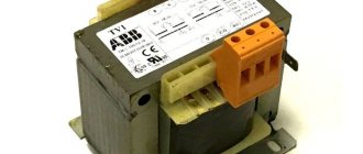
Current
You can connect the primary winding in series in an electrical circuit with other devices and obtain galvanic isolation. Such devices are called current transformers. The primary circuit of such devices is controlled by changing the single-phase load, and the secondary coil is used in measuring instrument or alarm circuits. The second name for the devices is instrument transformers.
A special feature of the operation of instrument transformers is the special mode of the output winding. It operates in critical short circuit mode. When the secondary circuit breaks, a sharp increase in voltage occurs in it, which can cause breakdowns or damage to the insulation.
Current transformer
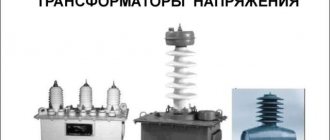
Voltages
A typical application is to isolate high-voltage protection logic circuits for measuring instruments. A voltage transformer is a step-down device that converts high voltage to lower voltage.
Pulse
These types of transformers are necessary for changing short-term video pulses, which, as a rule, are repeated in a certain period with a significant duty cycle, with a minimum change in their shape. The purpose of use is the transfer of an orthogonal electrical pulse with the steepest cut and front, a constant amplitude indicator.
The main requirement for devices of this type is the absence of distortion when transferring the shape of the converted voltage pulses. The action of a voltage of any shape on the input causes the output of a voltage pulse of an identical shape, but probably with a different range or changed polarity.
Dividing
For isolation transformers, interaction between the windings is eliminated. The devices increase the safety of electrical equipment in the event of damaged insulation.
Isolation transformer
Welding
In addition to the above, there is the concept of welding transformers. Specialized devices for welding work lower the voltage of the household network while simultaneously increasing the current, measured in thousands of amperes. The latter is adjusted by dividing the windings into sectors, which affects the inductive reactance.
Welding transformer
Coordinator
Matching transformers are used to equalize resistance between stages of electronic circuits. While maintaining the signal shape, they play the role of galvanic isolation.
Peak transformer
Using a peak transformer, sinusoidal voltage is converted into pulse voltage. In this case, the pulses change polarity with each half-cycle.
Twin throttle
A feature of a dual inductor is the identity of the windings. The mutual induction of the coils makes it more efficient than standard chokes. The devices are used as input filters in power supplies, audio and digital equipment.
Twin throttle
Air and oil
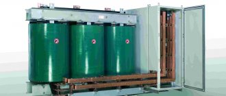
Power transformers are dry (air-cooled) (see Fig. 7) and oil-oil (see Fig. 8).
Models of dry power transformers are most often used to convert network voltages, including in three-phase network circuits.
Figure 7. Dry three-phase transformer
When a load is connected, the windings heat up, which threatens to destroy the electrical insulation. Therefore, oil-cooled devices operate in networks with voltages above 6 kV. Special transformer oil increases insulation reliability, which is very important at high output powers.
Rice. 8. Structure of an oil-cooled industrial transformer
Rotating
Used to exchange signals with rotating reels. Structurally, they consist of two halves of a magnetic circuit with coils. These parts rotate relative to each other. Signal exchange occurs at high rotation speeds.
Transformers - purpose, types and characteristics
To bookmarks
Introduction
A transformer is a static device having two or more windings, designed to convert, by electromagnetic induction, one or more alternating voltage and current systems into one or more other alternating voltage and current systems, usually having different values at the same frequency, for the purpose of transmitting power . (Source: GOST 30830-2002)
Fig.1 General view of the transformer
The importance of transformers both in the electric power industry in general and in the everyday life of every person can hardly be overestimated; they are used everywhere: at substations, in cities and towns, there are power transformers that lower high voltages of thousands and even tens of thousands of volts to the usual 380/220. Volt, enterprises have welding transformers that are absolutely indispensable in production; transformers are also used at home in household appliances: in microwave ovens, computer power supplies and even phone chargers.
In this article we will understand how transformers are structured and how they work, what types of transformers there are, and also give their general characteristics.
General structure and principle of operation of transformers
In general, a transformer consists of two windings located on a common magnetic circuit. The windings are made of copper or aluminum wire in enamel insulation, and the magnetic core is made of thin varnish-insulated electrical steel plates to reduce electricity losses due to eddy currents (the so-called Foucault currents).
The winding that is connected to the power source is called the primary winding, and the winding to which the load is connected is called the secondary winding. If a voltage (U2) is removed from the secondary winding (W2) of a transformer lower than the voltage (U1) supplied to the primary winding (W1), then such a transformer is considered a step-down transformer, and if higher, it is considered a step-up transformer.
Fig. 2 Diagram of the general structure of the transformer
The metal part on which the electrical winding (coil) is located, i.e. which is located in its center is called a core, in transformers this core has a closed design and is common to all windings of the transformer, such a core is called a magnetic circuit.
As mentioned above, the operating principle of transformers is based on the law of electromagnetic induction; to understand how this works, let’s imagine the simplest transformer, similar to the one shown in Figure 2, i.e. we have a magnetic circuit on which there are 2 windings, imagine that the first winding consists of only one turn, and the second - of two.
Now let’s apply a voltage of 1 Volt to the first winding, its only turn will conditionally create a magnetic flux of 1 Wb (For reference: Weber (Wb) is a unit of measurement of magnetic flux) in the magnetic core, since the magnetic core has a closed design; the magnetic flux will flow in it in a circle while crossing 2 turns of the second winding, in each of these turns, due to electromagnetic induction, it induces (induces) an electromotive force (EMF) of 1 Volt, the EMF of these two turns adds up and at the output from the second winding we get 2 Volts.
Thus, by applying 1 Volt to the primary winding, we received 2 Volts on the secondary winding, i.e. in this case, the transformer will be called a step-up transformer, because it increases the voltage applied to it.
But this transformer can also work in the opposite direction, i.e. if 2 Volts are applied to the second winding (with two turns), then from the first winding according to the same principle we will receive 1 Volt, in this case the transformer will be called a step-down transformer.
General characteristics of transformers
The main technical characteristics of transformers include:
- rated power;
- rated voltage of windings;
- rated current of windings;
- transformation ratio;
- efficiency;
- number of windings;
- operating frequency;
- number of phases.
Power is one of the main parameters of transformers. The passport (factory) data of the transformer indicates its total power (indicated by the letter S), it depends on the type of magnetic circuit used, the number and diameter of turns in the windings, that is, on the weight and dimensions of the electromagnetic device.
Power is measured in units of VA (Volt-Ampere). In practice, for high-power transformers, as a rule, multiples of Volt-Amps are used: Kilovolt-ampere - kVA (103 VA∙A) and Megavolt-ampere - MVA (106 VA∙A).
In fact, each transformer has 2 power values: input (S1) - the power that the transformer consumes from the network supplying it and output (S2) - the power that the transformer gives to the load connected to it, while the output power is always less than the input due to electrical losses in in the transformer itself (winding heating losses, eddy current losses, etc.), the magnitude of these losses is determined by another main parameter - the coefficient of performance, abbreviated as efficiency (denoted by the letter η), this parameter is indicated as a percentage.
For example, if the efficiency is specified as 92%, this means that the output power of the transformer will be 8% less than the input power, i.e. 8% is the loss in the transformer.
Power calculation formulas:
- Input power: S1=U1x I1 ,VA;
- Output power: S2=U2x I2 ,VA;
Where:
- I1, I2 - respectively, currents in the primary and secondary windings of the transformer in Amperes;
- U1, U2 - respectively, the voltages of the primary and secondary windings of the transformer in Volts.
It should be remembered that total power consists of active (P) and reactive (Q) powers:
- Active power is determined by the formula: P=U x I x cosφ , Watt (W)
- Reactive power is determined by the formula: Q=U x I x sinφ , volt-ampere reactive (Var)
- Power factor: cosφ=P/S;
- Reactive power factor: sinφ =Q/S
Formulas for calculating the efficiency (η) of a transformer:
As already mentioned above, the efficiency determines the amount of losses in the transformer or, in other words, the operating efficiency of the transformer and is determined by the ratio of the output power ( P2 ) to the input power ( P1 ):
η=P2/P1
As a result of this calculation, the efficiency value is determined in relative units (in the form of a decimal fraction), for example - 0.92, in order to obtain the efficiency value as a percentage, the calculated value must be multiplied by 100% (0.92*100%=92%).
The closer the efficiency is to 100%, the better, i.e. an ideal transformer is a transformer in which P2=P1 , but in reality, due to losses in the transformer, the output power is always lower than the input power.
This can be clearly seen from the so-called energy diagram of the transformer (Fig. 3):
- P1 is the active power consumed by the transformer from the source;
- P2 - active (useful) power supplied by the transformer to the receiver;
- ∆Pel - electrical losses in the transformer windings;
- ∆Рм — magnetic losses in the magnetic core of the transformer;
- ∆Рdop - additional losses in other structural elements.
In the no-load mode (operation without a load connected to the transformer), the efficiency of the transformer is η = 0. The no-load power P0 consumed by the transformer in this mode is spent on compensating for magnetic losses. With increasing load in a fairly small range (approximately β = 0.2), the efficiency reaches large values. In the rest of the operating range, the efficiency of the transformer remains at a high level. In modes close to the nominal one, the efficiency of the transformer is η nom = 0.9 - 0.98.
The dependence of efficiency on load is presented in the following graph (Fig. 4):
The primary rated voltage U1n is the voltage that must be applied to the primary coil of the transformer in order to obtain the rated secondary voltage U2n in no-load mode.
The secondary rated voltage U2н is the value that is set at the terminals of the secondary winding when the rated primary voltage U1н is applied to the primary winding in no-load mode.
Rated primary current I1н is the maximum current flowing in the primary winding, i.e. consumed by the transformer from the network for which this transformer is designed and at which its long-term operation is possible.
The rated secondary current I2n is the maximum load current flowing in the secondary winding for which this transformer is designed and at which its long-term operation is possible.
Transformation ratio ( kt) is the ratio of the number of turns in the primary winding to the number of turns in the secondary winding k=W1/W2.
Also kt is defined as the ratio of voltages at the winding terminals: kt = U1n/U2n.
For a step-down transformer, the transformation ratio is greater than 1, and for a step-up transformer, it is less than 1.
Note: for current transformers kt is defined as the ratio of the rated values of the primary and secondary currents kt = I1n/I2n
The number of windings for single-phase transformers is usually two, but can be more. One voltage value is applied to the primary winding, and another value is removed from the secondary winding.
When different voltages are required to power several devices, then in this case there may be several secondary windings. There are also transformers with a common point on the secondary winding for bipolar power supply.
The operating frequency of transformers may vary. But with the same primary winding voltages, a transformer designed for a frequency of 50 Hz can be used at a mains frequency of 60 Hz, but not vice versa. At a frequency lower than the nominal one, the induction in the magnetic circuit increases, which can lead to its saturation and, as a consequence, a sharp increase in the no-load current and a change in its shape. At a frequency higher than the rated one , the magnitude of parasitic currents in the magnetic core increases, the heating of the magnetic core and windings increases, leading to accelerated aging and destruction of the insulation.
The dimensions of the transformer directly depend on the frequency of the current in the circuit in which it will be installed. Of course, the transformer must be designed for this frequency. This dependence is inverse, i.e. As the frequency increases, the dimensions of the transformer decrease significantly. That is why switching power supplies (with pulsed high-frequency transformers) are much more compact.
Depending on the purpose, transformers are made single-phase and three-phase.
A single-phase transformer is a device for transforming electrical energy in a single-phase circuit. Basically it has two windings, primary and secondary, but there can be several secondary windings.
A three-phase transformer is a device for transforming electrical energy in a three-phase circuit. Structurally, it consists of three magnetic cores connected by an upper and lower yoke. Each rod is equipped with windings W1 and W2 of the highest (U1) and low (U2) voltages of each phase (Fig. 5).
Types of transformers
All transformers can be divided into the following types:
- power;
- autotransformers;
- measuring;
- dividing;
- coordinating;
- pulse;
- peak transformers;
- welding
Power transformers are the most common type of industrial transformer. They are used to increase or decrease voltage. They are an integral part of the power supply network for enterprises, settlements, etc.
An autotransformer is a transformer that has only one winding with the number of turns W1. Part of this winding with the number of turns W2 belongs simultaneously to the primary and secondary circuits:
This type of transformers is used in automatic voltage regulation devices. These devices are used, for example, in educational institutions for carrying out laboratory work; they can be found in electrical laboratories of various enterprises for carrying out test work.
Appearance of autotransformers:
Instrument transformers are divided into voltage transformers and current transformers. They provide galvanic isolation between high and low voltage circuits. As the name suggests, the main application is to reduce the primary voltage or current to a value used in measuring circuits, for example for connecting ammeters, voltmeters, and electricity meters. They can also be used in various protection, control and signaling circuits. They differ from other types of transformers by increased accuracy and stability of the transformation ratio.
Example of instrument transformers:
→ Read more about instrument transformers here.
Isolation transformers , these devices are not much different from conventional step-down or step-up transformers. The only difference is that absolutely identical windings are placed on a common magnetic core. That is, they completely match such parameters as wire cross-section, number of turns, insulation. Therefore, their transformation coefficient is equal to one.
The task of these devices is to provide galvanic isolation, i.e. exclusion of direct electrical connection between the electrical network and the equipment connected to it through this transformer.
They are used in areas where there are increased requirements for electrical safety, such as connecting medical equipment.
Matching transformers are used to match the resistance of various parts of cascades of electronic circuits, as well as to connect a load that does not correspond in resistance to the permissible values of the signal source, which makes it possible to transfer maximum power to such a load. In this case, the direct change in current and voltage indicators does not matter.
They are used in low-frequency amplifiers as input, interstage and output transformers.
As input, matching transformers are used in sound-reproducing equipment to connect microphones and sound pickups of various types.
Transformers of this type are used to match the signal when connecting antennas to receiving and transmitting devices.
Pulse transformers are devices with a ferromagnetic core that are used to change pulses of current or voltage. Convert the received signal into a rectangular pulse. Used to prevent high frequency interference. Pulse transformers are most often used in electronic computing devices, radar systems, pulse radio communications, and as measuring devices in electricity meters
Peak transformers - convert sinusoidal voltage into pulse peaks while maintaining their polarity and oscillation frequency.
Indispensable where starting the actuator requires a single pulse with a set voltage amplitude. These are, for example, control electronic circuits assembled using thyristors. They are also used as pulse generators, mainly in high-voltage research facilities, communications and radar technology. Peak transformers are most widely used in process automation.
Welding transformers are the main power sources for manual arc welding on alternating current. They serve to reduce the network voltage from 220V or 380V to a safe one and at the same time increase the current value to increase the temperature of the electric arc.
→ Read more about welding transformers here.
Was this article useful to you? Or maybe you still have questions ? Write in the comments!
Didn’t find an article on the website on a topic that interests you regarding electrical engineering? Write to us here. We will definitely answer you.
↑ Up
0
https://elektroshkola.ru/transformatory/transformatory-naznachenie-vidy-i-xarakteristiki/
A little history
Thanks to the English physicist Michael Faraday, in 1831, humanity became acquainted with electromagnetic induction. The great scientist was not destined to become the inventor of the transformer, since his experiments involved direct current. The prototype of the device can be considered the unusual induction coil of the Frenchman G. Ruhmkorff, which was presented to the scientific world in 1848.
In 1876, Russian electrical engineer P. N. Yablochkov patented an alternating current transformer with an open core. The device owes its modern appearance to the English brothers Hopkinson, as well as the Romanians K. Tsiperanovsky and O. Blati. With their help, the design acquired a closed magnetic circuit and has preserved the circuit to this day.
Types of magnetic cores
Decoding the main parameters
The diversity in design and wide range of parameters of transformers have led to the need for their marking according to a special standard. Without having a technical description at hand, the characteristics of the device can be determined by the information printed on its surface, expressed in an alphanumeric code.
The marking of power transformers contains 4 blocks.
Let's decipher the first three blocks:
Decoding of markings: 1,2,3 blocks
- The first letter "A" is attached behind the autotransformers. In its absence, the letters “T” and “O” correspond to three-phase and single-phase transformers.
- The further presence of the letter “P” informs about devices with split winding.
- The third letter means cooling; the oil natural cooling system is assigned the letter “M”. Natural air cooling is marked with the letter “C”, oil cooling with forced airflow is designated “D”, with forced oil circulation – “C”. The combination “DC” indicates the presence of forced oil circulation with simultaneous air blowing.
- The letter “T” marks three-winding converters.
- The last sign characterizes the features of the transformer:
- “N” – on-load tap-changer (voltage regulation under load);
- space – switching without excitation;
- “G” – lightning protected.
General technical requirements
The choice of technical characteristics is associated with some difficulties and the need for complex calculations. It will be necessary to calculate costs with the effect of energy losses in the network cable, taking into account the minimization of costs incurred.
Voltage 6-35 kV
Placement category - 1,2, 3 and 4. Climatic modifications U, UHL and KHL. Basic technical requirements:
- maximum and minimum temperature indicators - from plus 40 to minus 60 at UHL and HL1, at UHL4 -1;
- altitude above sea level - 1000 meters;
- seismic resistance - up to 6 points;
- voltage class - 6, 10, 15, 20 and 35 kV;
- rated voltage - 6.6; eleven; 17.5; 22 and 38.5 kV;
- highest operating voltage - 7.2; 12; 17.5; 24 and 40.5 kV;
- rated throughput power - 10000, 16000, 25000, 40000, 63000 kV;
- maximum heating of the windings - up to 65 degrees;
- loads and overloads - according to GOST 14209;
- tank pressure - 50 kPa.
The design is provided with an input with dismantling and scheduled repairs, there is a built-in current transformer, an M cooling system, a system for protecting the oil from contact with ambient air, voltage regulation devices, a device for monitoring the oil position and protecting against impurities, pumping and lifting.
6-20 kV
Placement category - 1,2, 3 and 4. Climatic versions U, UHL and KHL. Basic technical requirements:
- maximum and minimum temperature indicators - from plus 40 to minus 60 at UHL and HL1, at UHL4 -1;
- altitude above sea level - 1000 meters;
- seismic resistance - up to 6 points;
- voltage class - 6, 10, 15, 20 kV;
- rated voltage - 6; 10; 15 and 20 kV;
- highest operating voltage - 7.2; 12; 17.5; 24 kV;
- rated throughput - requirements;
- maximum heating of the windings - up to 65 degrees;
- current - 100, 150, 200, 300, 400, 500 and 600.
Requirements are established for the individual components of the mechanism. Installation of the control unit is individual.
0.4 kV
Placement category - 1,2, 3 and 4, standard climate control.
- voltage class - 6, 10, 15 kV;
- highest operating voltage - 6, 10, 15 kV;
- loads and overloads - according to GOST 14209;
- tank pressure - 50 kPa;
- grounding M12.
It is equipped with built-in current switches, all branches are inserted into the box. A system is installed to protect the oil from contact with air.
Safety precautions
During operation, certain rules must be observed:
- if cracks appear on the case, noise or vibration, the autotransformer is immediately turned off;
- It is prohibited to leave equipment for which continuous monitoring is provided unattended;
- you cannot connect a motor whose power is more than 70% greater than the power of the autotransformer;
- These devices must not be used openly, covered, covered with ventilation openings, or placed on them with other equipment or objects.
When carrying out repairs on an autotransformer or the device it is part of, it is necessary to disconnect it from the power supply.
Areas of different technologies
For example, electric furnace transformers are used to power electrothermal installations. Such transformers usually operate at a frequency of 50 Hz, and their power can reach tens of thousands of kilovolt-amperes at voltages up to 10 kV.
In the field of electric welding, welding transformers are widely used, the power of which is much less than that of electric furnaces.
As a case of a single application, the Tesla transformer, which is used to create special effects in the show industry.
To supply power to various electrical circuits of radio and television equipment, automation and telemechanics, communication products, electrical household appliances; as well as for separating and (or) matching the voltages of the circuits of various elements of the above devices, etc.
These transformers are usually low-power (volt-ampere to several kilovolt-ampere). They can have two or more windings, operate at low voltages, mainly at a frequency of 50 Hz, but much less often at higher frequencies (up to tens of kilohertz). The operating conditions of the above transformers can often be specific, which can cause increased requirements in manufacturing and design.
Types of transformers
Depending on their application and characteristics, transformers come in several types. For example, in electrical networks of populated areas and industrial enterprises, power transformers are used, the main task of which is to reduce the voltage in the network to the generally accepted 220 V. If a transformer is designed to regulate current, it is called a current transformer, and if the device regulates voltage, then it is a transformer voltage. In ordinary networks, single-phase transformers are used; in networks with three wires (phase, neutral, ground), a three-phase transformer is needed. Household transformer, 220V, is designed to protect household appliances from voltage surges.
Types of transformers
The welding transformer is designed to separate the welding and power networks, to reduce the voltage in the network to the value required for welding. The oil transformer is intended for use in networks with voltages above 6,000 Volts. The design of the transformer includes: a magnetic core, windings, a tank, as well as covers with inputs. The magnetic core consists of 2 sheets of electrical steel, which are insulated from each other; the windings are usually made of aluminum or copper wire. Voltage regulation is done using a tap that connects to the switch. There are two types of tap switching: switching under load - on-load tap-changer (regulation under load), and also without load, after the transformer is disconnected from the external network (PBV, or switching without excitation). The second method of voltage regulation has become more widespread.
Speaking about the types of transformers, it is impossible not to talk about the electronic transformer. An electronic transformer is a specialized power source that is used to convert 220V voltage to 12 (24)V at high power. The electronic transformer is much smaller than a conventional one, with the same load parameters.
Sources
- https://www.asutpp.ru/transformator-prostymi-slovami.html
- https://OFaze.ru/elektrooborudovanie/transformator
- https://ProTransformatory.ru/vidy/naznachenie-i-ustrojstvo
- https://agregat-impuls.ru/info/24-tipy-i-klassifikacija-transformatorov.html
- https://oooevna.ru/vidy-transformatorov/
Power transformers
Electricity is transmitted through high-voltage lines from generators, where it is generated to high-voltage consumer substations, in order to reduce losses, at high voltages of 35-110 kilovolts and above. Before we can use this energy, its voltage must be lowered to 380 volts, which is supplied to electrical panels located in the basements of apartment buildings. Three-phase transformers are usually designed for higher power. In electrical networks at transformer substations there are transformers that reduce the voltage from 35 or 110 kilovolts to 6 or 10 kilovolts; probably everyone has seen such transformers the size of a small house:
Photo high voltage transformer
Transformers from 6-10 kilovolts to 380 volts are located near consumers. Such transformers are located at transformer substations located in many courtyards. They are smaller in size, but together with HVs (load switches) that are placed in front of the transformer and input circuit breakers and feeders, they can occupy a two-story building.
Transformer 6 kilovolt
Three-phase transformers have windings that are connected differently than single-phase transformers. They can be connected into a star, a triangle and a star with the neutral removed. The following figure shows, as an example, one of the connection diagrams for the high voltage and low voltage windings of a three-phase transformer:
An example of connecting the windings of a power transformer
Transformers exist not only for voltage, but also for current. Such transformers are used to safely measure current at high voltage. Current transformers are designated in the diagrams as follows:
Current transformer diagram image
The photo below shows exactly these current transformers:
Current transformer - photo
There are also so-called autotransformers. In these transformers, the windings have not only magnetic coupling, but also electrical coupling. This is how a laboratory autotransformer (LATR) is designated in the diagrams:
Laboratory autotransformer - diagram image
LATR is used in such a way that by turning on part of the winding, using a regulator, you can obtain different output voltages. A photograph of a laboratory autotransformer can be seen below:
Photo LATR
In electrical engineering, there are schemes for safely switching on LATR with galvanic isolation using a transformer:
Safe LATR image on the diagram
A matching transformer is used to match the resistance of different parts of the circuit. Instrument transformers are also used to measure very large or very small voltages and currents.