Despite the constant improvement of the architecture of modern new buildings, any power supply scheme for an apartment building is based on a standard design.
To some extent, this fact simplifies the development of electrical projects in this category, but it is still necessary to take into account that some of the architectural innovations significantly change the technical conditions that determine their development.
Thus, the installation of some models of roof-top boiler houses, actively used in modern new buildings, automatically increases the reliability category of the power supply of the entire building to the first, which can become a serious obstacle when passing approval, and therefore will require significant modification of the project.
Let us immediately emphasize that in some cases, completely dead-end situations may arise when an object similar to a rooftop boiler house is already included in the main construction project, and the additional power line necessary to achieve the first category of reliability is not even theoretically available.
To avoid such inconsistencies during construction and major repairs, we will consider the main components of the energy supply system of a multi-storey building and their impact on the final complexity of the project.
What regulations regulate electricity supply in apartment buildings?
The legislation regulating the electricity supply system in MKD is systematically adjusted and is quite extensive. Let's get acquainted with some documentation that is directly related to the issue of power supply.
The electricity retail market is regulated by Federal Law No. 35-FZ dated March 26, 2003 “On Electric Power Industry”. The conditions for the provision of utility services for electricity supply in apartment buildings are adopted by the Rules for the provision of utility services to owners of residential premises and tenants of space in apartment buildings, approved by Decree of the Government of the Russian Federation of May 6, 2011 N 354. In accordance with Regulation No. 1 of these Rules, a permissible stop in the provision of utilities and acceptable inconsistencies in the quality of these utilities with the normative GOST 32144-2013, the conditions and process for adjusting the amount of payment for the provided utilities of poor quality and/or with interruptions that exceed the permissible time established at the legislative level.
For example, the possible duration of an interruption in the power supply of an apartment building belonging to the second reliability category (if there are two independent transformers) is 120 minutes, and for apartment buildings that belong to the third reliability category (there is only one transformer) - one day. For each hour that goes beyond the boundaries of the norm established at the legislative level, the amount of payment for utility services for the estimated time is reduced by 0.15% of the amount established for the given settlement period in accordance with Appendix No. 2, taking into account the paragraphs of the ninth section.
Typically, the power supply to MKD occurs through the main distribution board (MSB) or input distribution device (IDU). In this case, all subscribers are powered from a 220/380 V network with a solidly grounded neutral (TN-CS system). The main switchboard includes a circuit breaker and control devices that allow you to separately disconnect power consumers. The main switchboard distributes power supply voltage to group consumers (lighting of stairwells, basements, attics, elevator equipment, fire and emergency alarms, residential premises, etc.).
Electricity supply to residential premises is carried out through risers, through an RCD. Floor distribution panels are connected to the supply risers, forming a power supply network for the apartments. Floor electrical panels usually include electricity meters, circuit breakers and RCDs. Circuit breakers are grouped for each power supply circuit (lighting, sockets, electric stove, washing machine, etc.). To ensure an even load on the distribution network, the power circuits of different apartments are connected to different phase conductors.
What is included in a standard project
As mentioned above, load calculations and redundancy schemes in typical residential building power supply projects are carried out as for the second reliability category.
This means that all electricity consumers, in addition to other distributions, are divided into two main groups: the main one and those requiring continuous power.
Connection to an external power supply network for the main group of consumers is carried out without the use of automatic transfer switches (second category). The remaining subnets are connected via a UPS or in circuits switched by an automatic transfer device (first category).
As a rule, the additional group includes the following devices:
- control and dispatch systems;
- electrical installations of autonomous boiler houses;
- elevator equipment;
- fire alarm;
- power plants for smoke removal systems;
- emergency and temporary lighting;
- night marker lamps (for high-rise buildings).
Potential equalization scheme
In addition, typical power supply projects for residential buildings must include calculations for the following systems:
- providing lightning protection;
- main and additional grounding loops;
- measures to organize a potential equalization scheme.
To structurally divide the general power supply network of a building into functional zones, architectural features are used:
- technical underground electrical network;
- lighting and power equipment installed on the roof;
- emergency staircase lighting;
- electrical floor plans;
- general and floor distribution boards;
- power supply for elevator equipment.
Group lighting network and technical underground plan
The graphic and calculation part must include:
- single-line power supply diagrams for all distribution boards;
- group lighting network and technical underground plan;
- calculation of grounding and lightning protection;
- calculations and drawings of the main potential equalization system.
In some cases, the drawings include a sample of mechanical and welded connections in grounding and lightning protection structures.
Separately, we note that in the current realities, standard projects are gradually losing their relevance, since competition in the housing construction market forces developers to constantly look for new solutions, including by modernizing the electrical equipment of the building.
Power supply categories
To better understand the differences in power supply schemes for a multi-storey building (both residential and any other), you need to know that power supply can be provided in different ways, differing significantly in reliability. The most difficult reliability category is the first. With it, residential buildings are powered by two cables. Each of them is connected to a separate transformer.
If one transformer or cable fails, the ATS (automatic transfer switch) device will immediately transfer all power to the working cable. Thanks to this, problems with the power supply will occur in a matter of seconds. After a group of electricians left and repaired the failed equipment, electricity supply is maintained as usual.
In order to correctly understand the various power supply schemes for residential buildings , you need to know about the three categories of ensuring the reliability of power supply to electrical installations. The simplest category is the third. It provides power to a residential building from a transformer substation via a single electrical cable. Moreover, in the event of an emergency, the interruption in the power supply to the house should be less than 1 day.
With the second category of power supply reliability, a residential building is powered by two cables connected to different transformers. In this case, if one cable or transformer fails, the power supply to the house while the fault is being eliminated is carried out through one cable. An interruption in power supply is allowed for the time necessary for the electrical personnel on duty to connect the loads of the entire house to the operating cable.
There are two types of power supply at home from two different transformers. Either the loads of the house are evenly distributed across both transformers, and in emergency mode they are connected to one, or in operating mode one cable is used, and the second is a backup. But in any case, the cables are connected to different transformers. If two cables are laid in the electrical panel of a house , one of which is a backup, but it is possible to connect these cables to only one substation transformer, then we have only the third category of reliability.
With the first category of power supply reliability, a residential building is powered by two cables, just as with the second category. But if a cable or transformer fails, the loads of the entire house are connected to the working cable using an automatic transfer switch (ATS).
There is a special group of electrical receivers (fire alarms, smoke removal systems in case of fire, evacuation lighting and some others), which must always be powered according to the first reliability category. For this purpose, backup power sources are used - batteries and small local power plants.
According to existing standards for the third category of reliability, electricity is supplied to houses with gas stoves with a height of no more than 5 floors, houses with electric stoves with the number of apartments in the house less than 9 and houses of gardening associations.
Electricity supply in the second reliability category applies to houses with gas stoves with a height of more than 5 floors and houses with electric stoves with more than 8 apartments.
According to the first reliability category, it is mandatory to supply electricity to heating points of apartment buildings, and in some buildings, elevators. It should be noted that the first category mainly supplies electricity to some public buildings: these are buildings with more than 2000 employees, operating rooms and maternity wards of hospitals, etc.
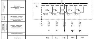
The figure shows the power supply diagram for four entrance houses, powered according to the second reliability category with a backup cable. The supply cables are switched using a reversing switch having positions “1”, “0” and “2”. In position "0" both cables are disconnected. The circuit breakers QF1...QF4 feed the lines that run along the access vertical risers, from which power is supplied to the apartments. General house loads: lighting of staircases, basements, lamps above the entrance doors to the entrances are powered by a separate group containing its own electricity meter.
Depending on the number of apartments in the house, all electrical equipment can be placed in one electrical cabinet or in several.
Differences between modern projects and standard solutions
To answer the question of how an individual electrical project for an apartment building differs from a standard one, we list the most popular architectural and technical innovations used in modern new buildings.
Roof boiler room
First of all, these are systems designed to ensure autonomy and savings in the field of heat supply, the most original of which can be called rooftop boiler rooms.
SNiP II-35-76 (“Design standards. Boiler installations”) states that, depending on the power, such systems can be classified into the first or second categories of power supply reliability.
Considering that most modern boiler houses are equipped with powerful turbocharged burners, it is possible to provide “I category” for them only through a backup power feeder or using a diesel generator.
It often happens that the systems listed above are installed during a major home renovation. In this case, the design documentation includes an as-built power supply diagram indicating all changes made.
The second difference between modern housing cooperatives and classic nine-story panel buildings, during which standard standards were developed, is the presence of underground parking lots, the electrical networks of which, as a rule, are included in the balance sheet responsibility of the new building.
Let us note that even in cases where the parking is located not in the basement area of the house, but in the local area, the owners of housing cooperatives try to combine their electrical networks, as this significantly affects the cost of electricity consumed.
From a design point of view, this means the need to organize uninterrupted power supply for smoke removal and emergency lighting systems installed in underground parking.
To be fair, we note that a modern electrical design for a multi-storey entrance is not always more complicated than the typical example described above, since many buildings are initially designed for the sale of apartments in the so-called “rough finish” state, when the apartments have no internal electrical wiring at all.
Ring diagram of power supply for an apartment building
Ring power supply diagram for an apartment building is a plan for installing and connecting electrical receivers, according to which power supply to an apartment building is possible via two cable lines forming a ring. This ring diagram looks like this:
The first and last electrical receivers are connected from the main power source, and so-called jumpers are created between all remaining electrical receivers.
To create such a ring plan, two changeover switches should be provided in the ASU for each apartment building.
In normal mode, the power is evenly divided between the two inputs.
In order to understand why this circuit requires exactly two switches, we let you consider a number of possible emergency situations:
- Failure of one of the supply cable lines
In such a situation, the power supply to all multi-apartment residential buildings comes from one cable line.
Specialists from the management company install the switches in the required position.
- Jumper failure
Workers are required to isolate from the power supply circuit the area where the accident occurred (for example, a short circuit occurred on the line). One part of the houses is powered by one cable line, and the second part of the residential buildings is powered by another. Instead of two changeover switches, you can use three regular ones.
Do I need to pay for the project?
It was already mentioned above that the cost of a power supply project for an apartment building is quite high. And many construction customers are seriously thinking: is it necessary to spend extra money when ordering design? Indeed, today there are dozens of sites on the Internet where you can download suitable projects for a wide variety of houses: from 4-apartment buildings to huge skyscrapers with hundreds of classrooms and offices. Using a ready-made project would save tens of days of work and tens (and maybe hundreds!) of thousands of rubles.
Electricity supply rules
The general rules for power supply to a residential building are regulated by Decree of the Russian Federation No. 354. The management organization ensures the provision of electricity to the consumer. Consumers must pay it on time.
To provide electricity supply, the following actions are carried out:
- Concluding an agreement with a local energy supply organization.
- Development of technical specifications.
- Drawing up a house electrification scheme with calculation of the power of the devices intended for use. This is necessary to determine the cable cross-section and calculate the optimal power reserve.
- Installation and sealing of the metering device, ASU.
- Cable installation.
- Equipment selection.
- Checking compliance and issuing an act of commissioning into the distribution zone.
- Receipt of the document: “Act of fulfillment of specifications” and an agreement for the provision of electricity.
Self-connection is prohibited. The supplying company provides its employees.
Requirements for installing the main elements of the electrical network at home
The electrical network of a private home can be divided into several components. One of the first of these is the input of electricity into the house, followed by the distribution panel, of which there may be two or more. A separate issue is the distribution of electricity throughout the house, as well as outside the premises.
Input of electricity into a private house
One of the most “painful” issues is connecting the house to the power supply. This action is carried out by your Energosbyt enterprise.
To make the connection, it will require you to provide a home power supply project, as well as technical connection conditions. It is quite problematic to prepare all this documentation with your own hands, so it is easier to contact specialized organizations.
We will focus on the purely technical aspects of introducing electricity into the building. Entry into the house can be carried out in two ways - cable or overhead line. In practice, Energosbyt in 90% of cases requires input via an overhead line, which is easier to check for theft.
Overhead entry is usually done with SIP wire. The number of cores and its cross-section depend on the nominal parameters of the supply network. For a conventional single-phase input, a wire with a phase conductor cross-section of 16 mm2 is usually sufficient.
The distance from the house to the main network pole should be no more than 25 meters. If this distance is higher, then the installation of an additional pole will be required.
The height of the wire fastenings on the house must be at least 2.75 meters. In this case, the wire must be removed from the roof canopy by at least 20 cm. When laid in parallel with the facade of the house in accordance with clause 2.4.57 of the PUE, the wire must be at least 20 cm removed from the wall of the house and at least 1 meter from windows, balconies or terraces.
Before installing electrical wiring in a private house, you should resolve the issue of installing a meter. Recently, its installation on the facade of a house has become increasingly practiced. This allows you to connect from the meter to the switchboard using a more convenient cable.
If the meter is located in a distribution board, then you will most likely be required to lay a SIP wire all the way to the board itself. This wire is quite inconvenient for laying it through the wall and for inserting it into the distribution panel, but Energosbyt may not make the connection otherwise.
Note! On various sites you can find a proposal for installing an input machine on the facade of the house, to the input of which a SIP wire is connected, and to the output a more convenient cable. But the rules of the PUE prohibit the installation of such machines.
The passage of the wire through the wall of the house must be carried out in a metal pipe. In this case, the pipe must be made in such a way as to prevent the ingress and accumulation of moisture in it.
Installation of distribution board
The power supply cable comes to the distribution panel. Here we have installed an introductory machine, in some cases a counter, group machines, means of protection and control of power quality, and automation equipment.
In fact, this is the “heart” of our electrical network at home, so the closest attention should be paid to its correct installation.
So: Before we figure out the location and method of installing the switchboard, let's figure out what electrical equipment is installed in it.
| Each distribution board must have an input circuit breaker. It can be single-phase or three-phase depending on the supply network. |
| If the meter is not installed on the facade of the house, then it is located in the distribution board. | |
| From the meter, power wires are usually connected to busbars. |
| Single-pole group circuit breaker | The tires are distributed into separate groups. Group automatic machines protect individual groups. |
| RCDs are designed to protect people from accidental contact. For some groups their installation is required | |
| Three-phase surge suppressor | For additional protection of the electrical network, surge suppressors are installed in the distribution board. Their installation is especially important for houses powered by overhead lines. |
| Three-phase power quality monitoring device | For additional control of power quality, it is possible to install special devices. It is important that these devices are licensed accordingly. So that their testimony could be used in court. |
| If we plan to have a 12V network in our electrical network, then it is also more practical to install transformers in the distribution board. |
Note! Distribution boards in which the installation of a meter is provided must be locked with a key. In addition, such shields must have glass to allow readings to be taken without opening the shield.
According to clause 7.1.28 of the PUE, distribution boards should be installed in dry rooms, in places convenient for maintenance. If this room is subject to flooding, then the installation height of the shield should be higher than the flood level.
The distance from gas, water and similar pipes should be at least 1 meter. In this case, the pipelines themselves should not have branches, valves or filters in this room. The only exceptions are branches to the heating registers of the room.
Clause 7.1.29 of the PUE prohibits the installation of distribution boards under bathrooms, kitchens, bathhouses and similar premises. Such installation is permitted only with appropriate waterproofing.
Before wiring in a private home, the distribution board must be properly installed. To do this, you can use mounted or built-in panels. And the choice of installation method largely depends on the type of wiring that you will use in the future:
- For rooms whose walls are made of flammable materials, it is better to use wall panels. At the same time, the shields themselves must be made of fireproof materials.
- For rooms whose walls are made of fireproof materials, shields made of combustible materials can be used. In this case, you can use both mounted and built-in type panels.
- According to clause 7.1.22 of the PUE, there may be more than one switchboard for a private house. If you have rooms that are economically separate, then it is better to organize a separate panel for them. It is usually installed in a garage or workshop. It is also usually used to power outdoor lighting. In some cases, another distribution board is installed for outdoor lighting.
Payment for electricity supply
An agreement on the provision of services is drawn up with the management company with the rights and obligations of each party specified.
Payment for electricity can be made in cash or non-cash in various ways using:
- bank cards;
- translations;
- Internet services.
Payment documents are retained for 3 years. Advance payment is allowed. Payment is due by the 10th of each month. The basis is payment documents based on approved tariffs.
Operational Responsibility Limit
The law has a concept of the limit of operational responsibility. Essentially, it separates what the building management company is responsible for and what the homeowner is responsible for.
For the power supply of an apartment, the boundary of operational responsibility “lies” at the place where the apartment’s power supply cable (wires) is connected to the circuit breaker (batch switch) installed upstream of the electric meter (electricity consumption meter) of the apartment.
This means that the electricity supply of the apartment, for which the owner is responsible, includes:
- general (for apartment) circuit breaker (input circuit breaker) or batch switch and/or fire protection RCD;
- Electricity consumption meter;
- Cable or wires from the meter to the apartment (if the apartment has an apartment panel);
- Circuit breakers between the apartment panel (if there is one) and the meter.
In apartments where there is no apartment board, the line of operational responsibility passes for each apartment in the floor board.
Electrical wiring diagrams in a private house: design rules and tips for electrical wiring
The electrical supply diagram of a private home is a lot of organized cables, wires, and protective devices. The correct selection of parameters and characteristics of the circuit elements guarantees the safety and comfort of property owners.
If the circuit is drawn up correctly, taking into account the requirements of the PUE and other regulatory documents, there is nothing to fear - there will always be light and warmth in the rooms, and electrical appliances will not break due to power surges or short circuits in the network. Therefore, special attention should be paid to electrical design.
We suggest you understand all the intricacies of this process. The article outlines the general requirements for designing an electrical network, provides practical advice on choosing wires, and also discusses in detail typical electrical wiring diagrams.
In addition, we have prepared a review of common mistakes, taking into account which will help to avoid shortcomings in the development and installation of power supply networks.
General rules for electrical network design
When there were few electrical appliances, and several 40-60 W light bulbs were enough for lighting, a primitive circuit was drawn up to set up the power supply system, including several switches and sockets.
Now, with the advent of a large number of energy-dependent household appliances, the circuit is necessarily differentiated into group lines protected by circuit breakers and other devices.
In just one kitchen, up to a dozen devices can be connected, 2-3 of which are powerful units that require dedicated power lines with a larger cross-section cable and separate sockets
If you think through all the nuances of the location of electrical wiring in a private house, taking into account the use of copper wire, it will last at least 20 years. Typically, a diagram is drawn up along with the design of a new house or before a major renovation.
You should start by indicating the installation locations of such elements as:
- sockets;
- switches;
- distribution boxes;
- lighting devices;
- powerful household appliances;
- electrical panel
At the same stage, you should decide on the method of laying the cables - open or closed. In houses with plastered walls, a closed method is usually used; in houses with wooden walls, an open method is used.
Whatever scheme you use, there are a number of rules that you cannot deviate from. They are prescribed in regulatory documentation, and their effectiveness has been proven for decades.
Here are a few important axioms of electrical installation that will be required to draw up a diagram:
Electrical wires and cables are laid horizontally and vertically. This standard reflects decades of experience in operating circuits. When laying a wire, it cannot be turned at an acute or obtuse angle; any turn of the line must be 90°.