AC RELAY
In railway automation and telemechanics devices, two-element sectoral alternating current relays of the DSSh type are used. These relays are used as track relays in AC track circuits with a frequency of 50 and 25 Hz. According to the principle of operation, two-element sector relays are classified as inductive. The relay's magnetic system is made of sheet steel cores to reduce hysteresis losses. These relays belong to reliability class 1 relays, and in terms of response time - to normally operating ones.
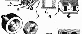
A two-element sector relay DSSh with plug-in connection (Fig. 1.10, a) consists of an electromagnetic system, which consists of two iron cores of different purposes with windings wound on them. One of them is called a local element, the other is a path element. These elements are located symmetrically one relative to the other.
The local element consists of an W-shaped core 1 with a winding 2, which is connected to a local alternating current source with a voltage of 110-220 V. The track element consists of a core 8 with a winding 9, which is connected through a track circuit to a track transformer. Between the poles of the local and track element cores there is an aluminum sector 4, which rotates on an axis and, with the help of a rocker arm 3 and a rod 5, controls the contact system 6. The relay has thrust rollers 7 and 10 that limit the movement of the sector down and up, respectively.
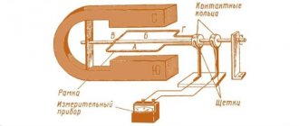
The operating principle of the relay is based on the interaction of the magnetic flux of the track element with the current induced in the sector by the magnetic flux of the local element. When one of the relay elements is without current, the sector, under the influence of its own weight, is in the lower extreme position and presses with its edge on the lower thrust roller. When an alternating current passes through the coil of a local element, the magnetic flux created by the current of the local element, crossing the sector, induces an emf in it, which is 90° out of phase from the flux that caused it. As a result of this, eddy currents arise in the sector, which pass under the poles of the track element, interact with its magnetic flux and create a torque that tends to rotate the sector. The interaction of eddy currents created by the magnetic flux of the track element with the magnetic flux of the local element leads to similar results. If the magnetic fluxes are equal and in phase, the forces of interaction between magnetic fluxes and eddy currents will be equal and oppositely directed, as a result of which the sector will remain in the lower position. To bring the sector into rotation in the direction of its rise, it is necessary to create a certain phase shift between the magnetic fluxes of the local and track elements or between their currents.
Thus, the maximum torque will be at a phase angle φ = 90 0 between the currents or magnetic fluxes in the local and track elements. This torque moves the sector to the upper position. Together with the sector, the rocker arm and rod rotate, which switches the contacts: opens the rear T and closes the front F. When the current in the track element is turned off, the magnetic flux disappears, and under the influence of its own weight, the sector will go down and return the contacts to their original position: open the front F and close rear T.
The symbols of the DSS relay and its contacts are shown in Fig. 1.10.6. The main advantage of DSS relays is reliable phase selectivity, which is why these relays are called phase-sensitive. The selectivity property reliably excludes false operation of the phase-sensitive track relay from the power source of the adjacent rail circuit when the insulating joints are closed, since the track windings of the relay are switched on in such a way that a positive torque and upward lift of the sector are created only from the current of its track circuit.
In addition, phase-sensitive relays provide reliable protection against the influence of traction current interference, which differs in frequency from the signal frequency current by only a few hertz. Phase-sensitive relays are triggered by a current of the same frequency as the frequency of the current in the winding of the local element, with certain phase relationships between them.
TRANSMITTERS
Transmitters are used in automation and telemechanics devices as pulse sensors. They serve to convert continuous direct or alternating current into pulsed current. The most widely used are pendulum MTs and code transmitters KPT.
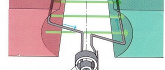
The pendulum transmitter (Fig. 1.11, a) is a direct current electromagnetic mechanism with a swinging armature.
Its main parts are: magnetic circuit 1 with coils, armature 2, on the axis 3 of which there is a pendulum 7 and getinaks cam washers 4, 5, 6.
The armature axis 01-02 is rotated relative to the M1-M2 axis and the vertical axis of the pendulum. When there is no current in the electromagnet windings, the pendulum 7 takes a vertical position, and the cam washer 4 closes the control contact of the AC, forming a power circuit for the windings.
When the K button is pressed, the transmitter cores are magnetized and armature 2 rotates, tending to align its axis 01-02 with the axis of the magnetic circuit Ml-M2. Together with the armature, pendulum 7 (to the right) and all the cam washers rotate, as a result of which washer 4 opens the contact of the remote control and, consequently, the power circuit of the electromagnet winding, and washers 5 and 6 close contacts 31-32 and 41-42. When the magnetic field disappears, pendulum 7 continues to move by inertia. Having reached the maximum deviation, it begins to move in the opposite direction and, by inertia, deviates to the right at a certain angle from the vertical position. At the moment when the pendulum 7 passes the vertical position, the control contact of the CC closes and a current flows through the electromagnet winding again, creating a magnetic flux, and contacts 31-32 and 41-42 open. Armature 2, under the influence of the magnetic field, will turn again, trying to take the position Ml-M2, swinging the pendulum. Thus, undamped oscillations of the transmitter pendulum occur. When the transmitter is operating, contacts 31-32 and 41-42 alternately close and open, which form uniform DC pulses.
Significant disadvantages of contact relays and transmitters are the dependence of service life on the number of operations and insufficient speed due to the presence of mechanical movements during operation of these devices. These disadvantages can be eliminated by using electronic devices that do not have moving rubbing elements.
Currently, electronic devices are increasingly being used in signaling devices. The elements of electronic devices are diodes, transistors, thyristors, zener diodes, logic elements, integrated circuits, microprocessors.
Examples of the use of such elements are the following electronic devices:
· contactless current switch (BKT), which is a more modern switching device for switching code current in AC track circuits with a frequency of 25 and 50 Hz. It consists of two thyristors and a control circuit. The principle of operation of this device is similar to the principle of operation of a contactless relay;
· microelectronic pulse sensor (DIM), which is produced to replace pendulum transmitters MT-1, MT-2;
· contactless code path transmitter (BCPT), which is used in code automatic blocking systems and serves to generate numeric codes KZH, ZH, and 3 using semiconductor devices and logical elements.
In railway automation and telemechanics devices, two-element sectoral alternating current relays of the DSSh type are used. These relays are used as track relays in AC track circuits with a frequency of 50 and 25 Hz. According to the principle of operation, two-element sector relays are classified as inductive. The relay's magnetic system is made of sheet steel cores to reduce hysteresis losses. These relays belong to reliability class 1 relays, and in terms of response time - to normally operating ones.
A two-element sector relay DSSh with plug-in connection (Fig. 1.10, a) consists of an electromagnetic system, which consists of two iron cores of different purposes with windings wound on them. One of them is called a local element, the other is a path element. These elements are located symmetrically one relative to the other.
The local element consists of an W-shaped core 1 with a winding 2, which is connected to a local alternating current source with a voltage of 110-220 V. The track element consists of a core 8 with a winding 9, which is connected through a track circuit to a track transformer. Between the poles of the local and track element cores there is an aluminum sector 4, which rotates on an axis and, with the help of a rocker arm 3 and a rod 5, controls the contact system 6. The relay has thrust rollers 7 and 10 that limit the movement of the sector down and up, respectively.
The operating principle of the relay is based on the interaction of the magnetic flux of the track element with the current induced in the sector by the magnetic flux of the local element. When one of the relay elements is without current, the sector, under the influence of its own weight, is in the lower extreme position and presses with its edge on the lower thrust roller. When an alternating current passes through the coil of a local element, the magnetic flux created by the current of the local element, crossing the sector, induces an emf in it, which is 90° out of phase from the flux that caused it. As a result of this, eddy currents arise in the sector, which pass under the poles of the track element, interact with its magnetic flux and create a torque that tends to rotate the sector. The interaction of eddy currents created by the magnetic flux of the track element with the magnetic flux of the local element leads to similar results. If the magnetic fluxes are equal and in phase, the forces of interaction between magnetic fluxes and eddy currents will be equal and oppositely directed, as a result of which the sector will remain in the lower position. To bring the sector into rotation in the direction of its rise, it is necessary to create a certain phase shift between the magnetic fluxes of the local and track elements or between their currents.
Thus, the maximum torque will be at a phase angle φ = 90 0 between the currents or magnetic fluxes in the local and track elements. This torque moves the sector to the upper position. Together with the sector, the rocker arm and rod rotate, which switches the contacts: opens the rear T and closes the front F. When the current in the track element is turned off, the magnetic flux disappears, and under the influence of its own weight, the sector will go down and return the contacts to their original position: open the front F and close rear T.
The symbols of the DSS relay and its contacts are shown in Fig. 1.10.6. The main advantage of DSS relays is reliable phase selectivity, which is why these relays are called phase-sensitive. The selectivity property reliably excludes false operation of the phase-sensitive track relay from the power source of the adjacent rail circuit when the insulating joints are closed, since the track windings of the relay are switched on in such a way that a positive torque and upward lift of the sector are created only from the current of its track circuit.
In addition, phase-sensitive relays provide reliable protection against the influence of traction current interference, which differs in frequency from the signal frequency current by only a few hertz. Phase-sensitive relays are triggered by a current of the same frequency as the frequency of the current in the winding of the local element, with certain phase relationships between them.
TRANSMITTERS
Transmitters are used in automation and telemechanics devices as pulse sensors. They serve to convert continuous direct or alternating current into pulsed current. The most widely used are pendulum MTs and code transmitters KPT.
The pendulum transmitter (Fig. 1.11, a) is a direct current electromagnetic mechanism with a swinging armature.
Its main parts are: magnetic circuit 1 with coils, armature 2, on the axis 3 of which there is a pendulum 7 and getinaks cam washers 4, 5, 6.
The armature axis 01-02 is rotated relative to the M1-M2 axis and the vertical axis of the pendulum. When there is no current in the electromagnet windings, the pendulum 7 takes a vertical position, and the cam washer 4 closes the control contact of the AC, forming a power circuit for the windings.
When the K button is pressed, the transmitter cores are magnetized and armature 2 rotates, tending to align its axis 01-02 with the axis of the magnetic circuit Ml-M2. Together with the armature, pendulum 7 (to the right) and all the cam washers rotate, as a result of which washer 4 opens the contact of the remote control and, consequently, the power circuit of the electromagnet winding, and washers 5 and 6 close contacts 31-32 and 41-42. When the magnetic field disappears, pendulum 7 continues to move by inertia. Having reached the maximum deviation, it begins to move in the opposite direction and, by inertia, deviates to the right at a certain angle from the vertical position. At the moment when the pendulum 7 passes the vertical position, the control contact of the CC closes and a current flows through the electromagnet winding again, creating a magnetic flux, and contacts 31-32 and 41-42 open. Armature 2, under the influence of the magnetic field, will turn again, trying to take the position Ml-M2, swinging the pendulum. Thus, undamped oscillations of the transmitter pendulum occur. When the transmitter is operating, contacts 31-32 and 41-42 alternately close and open, which form uniform DC pulses.
Significant disadvantages of contact relays and transmitters are the dependence of service life on the number of operations and insufficient speed due to the presence of mechanical movements during operation of these devices. These disadvantages can be eliminated by using electronic devices that do not have moving rubbing elements.
Currently, electronic devices are increasingly being used in signaling devices. The elements of electronic devices are diodes, transistors, thyristors, zener diodes, logic elements, integrated circuits, microprocessors.
Examples of the use of such elements are the following electronic devices:
· contactless current switch (BKT), which is a more modern switching device for switching code current in AC track circuits with a frequency of 25 and 50 Hz. It consists of two thyristors and a control circuit. The principle of operation of this device is similar to the principle of operation of a contactless relay;
· microelectronic pulse sensor (DIM), which is produced to replace pendulum transmitters MT-1, MT-2;
· contactless code path transmitter (BCPT), which is used in code automatic blocking systems and serves to generate numeric codes KZH, ZH, and 3 using semiconductor devices and logical elements.
Single-strand track circuits with track relays DSSH-12
General information. Single-thread DC AC 50 Hz with relay DSSh-12 and relay transformer RTE-1 are used on non-coded tracks and in the necks of stations of railway lines equipped with direct current electric traction. RC stations are powered by one phase of three-phase alternating current with a frequency of 50 Hz.
The short circuit of the insulating joints is controlled by alternating instantaneous voltage polarities at the joints of adjacent DCs by correspondingly switching on the secondary windings of the track transformers. The primary windings of track transformers and local elements of track relays of all DC stations must be connected to the same phase.
The supply and relay ends of adjacent DCs can be located in any way: r-t, r-r or m-t. Single-strand DCs do not allow the superposition of ALSN code signals. The track relay is located at the electrical center post, and the relay and track transformers, track resistors are located in transformer boxes or relay cabinets.
RC schemes. The maximum length of single-pipe unbranched DCs (Fig. 6.33, a) with a standard insulation resistance of 1 Ohm-km is 1100 m.
For these purposes, the total resistance of the travel resistor Rap and the connecting wires at the supply end must be equal to 1 Ohm, the total resistance of the protective resistor D and the connecting wires at the relay end must be at least 0.5 Ohm, and the cable resistance between the isolating transformer and the travel relay must not must exceed 100 ohms.
The maximum length of the cable between the travel relay and the isolating transformer, which does not require duplication of cores, is 2 km. When the distance between the travel relay and the relay end is greater, the duplication of cores is carried out based on the cable resistance of no more than 100 Ohms.
Rice. 6.33. Single-strand unbranched millet DC 50 Gp with relay DSSh-12 (a) and branched DC with two relays
DSSH-12 (b)
The cable conductor between the rails and the insulating transformer RC with a length of up to 1100 m is determined based on the calculated cable resistance of 0.5 Ohm.
The cable conductor between the rails and the track transformer of all RCs, as well as between the rails and the isolating transformer RC with reduced insulation resistance up to 500 m long and branched RCs, is determined based on the calculated cable resistance of 1 Ohm.
The conductor of the cable between the track transformer and the electrical center post is determined by the permissible voltage loss in the cable D?/k = 20
V and the calculated current in the primary winding of the track transformer. The voltage on the primary windings of track transformers and local elements of track relays must be at least 200 V.
The maximum length of single-strand RCs with reduced insulation resistance in the station's yurlovips, as well as branched RCs with two travel relays (Fig. 6.30, 6) is 500 m. In these circuits, the total resistance of the travel resistor and connecting wires at the supply end should be 2 Ohms , the total resistance of the protective resistor /?, and the connecting wires at the relay end is at least 1 Ohm, and the cable resistance between the isolating transformer and the travel relay should not exceed 100 Ohms.
Names and types of devices used in the DC, shown in Fig. 6.33, a and b\
| Name and designation in the diagram | Tin device |
| Track relays P, S11 | DSSH-12 |
| PSP travel relay repeater | NMSh1-1800 |
| Transformer: | |
| track PT | POBS-2A |
| IT isolation | RTE-1A |
| Protective filter ZF | RZF-1 (RZFSH-2) |
| Resistor: | |
| travel /?„ | 7156(2.2 Ohm, 10 A) |
| protective I, | 7156(2.2 Ohm, 10 A) |
| Automatic switch LVM | AVM 1 (5 and 10 A) |
| Fuse | 20871(2 A) |
Note - the types of instruments and equipment of the RC are given for the period of time of development of the RC collections.
Estimated powers and currents. The calculated powers and currents consumed by the primary windings of track transformers are given taking into account losses in transformers of the POBS-2A type.
When track transformers are connected to a 110 V network, the calculated currents double.
Adjustment. The RC is regulated by changing the voltage on the secondary winding of the track transformer (P2..1) of the PT at constant resistance values at the ends of the RC. The voltages on the track relays of the branched DC are equalized by protective adjustable resistors Dz.
Note - the adjustment parameters of the DC operating modes are presented as part of the DC collections.
⇐Single-strand track circuits with track relays НРВ1-1000, НВШ1-800, НМВШ2-900/900, НМВШ2-1000/1000 and АНВШ2-2400 | Automation, telemechanics, communications and computer technology on Russian railways | Double-strand track circuits with choke transformers and track relays DSSH-12⇒
IAPK RTU DSSH Electrical testing stand. parameters of signaling relays of DSSH types
Description The measuring hardware and software complex IAPK RTU DSSH is intended for operation in repair and technological sections of signaling and communication distances.
Using the IAPK RTU DSSH, the following DSSH relays are checked: DSSH-2, DSSH-12, DSSH-13, DSSH-13A, DSSH-15, DSSH-16.
Unlike analogues, for example, the stand of SP DSSH, IAPK RTU DSSH is maximally automated.
IAPK RTU DSSh measures the following electrical and timing parameters of the DSSh relay:
- contact circuit resistance;
- active resistance of windings;
- PE impedance;
- AC pickup/release voltage;
- AC pickup/release current strength;
- relay response time.
Metrological characteristics
The measurement ranges and limits of permissible relative basic measurement error are given in Table 1.
Table 1
| Parameter | Ranges measurements | Limits of permissible basic relative error, |
| Contact circuit resistance, Ohm | 0,02 – 0,20 0,20 – 2,00 | ± (2.5 + 0.25 (Rк/Rx – 1)) % |
| Active resistance of relay windings, Ohm | 40 – 100 100 – 600 | ± 1,0 % |
| Relay winding impedance, Ohm | 300 – 1000 | ± (1.5 + 0.2 (Zк/Zx – 1)) % |
| AC voltage with a frequency of 25, 50 and 75 Hz, V | 3 – 50 90 – 250 | ± (1.0 + 0.1 (Uк/Ux – 1)) % |
| AC power with frequency 25, 50 and 75 Hz, mA | 5 – 50 50 – 200 | ± (1.0 + 0.1 (Uк/Ux – 1)) % |
| Relay response time, ms | 100 ― 500 | Limit of permissible basic error - ± 1.0 ms |
| Phase shift, degrees PE voltage relative to ME voltage PE current relative to ME voltage | Minus 87 Minus 162, 20 | Limit of permissible basic error - ± 1.0 degrees |
The main relative error in measuring the voltage or alternating current of the relay actuation and release is no more than ± 4% (according to GOST 16121-86).
IAPK RTU DSSH provides power to ME and PE relays DSSH during testing with alternating current with a frequency of 25, 50 and 75 Hz in the voltage and current measurement ranges given in Table 1. The voltage output error is not standardized. The frequency error of the supply voltage of the DSS relay is no more than ± 0.01 Hz.
Basic properties
The complex is controlled from a PC keyboard or using a mouse.
The results of testing the DSS relay are displayed on the PC monitor screen, and upon completion of the test they are saved in the form of a protocol indicating the end of the test time.
The complex automatically determines the compliance of the measured relay parameters with established standards. Parameters that do not comply with the standards for the relays being tested are highlighted when the test results are displayed.
The complex provides storage of measurement results on the PC hard drive, as well as sorting, searching and outputting the test protocol to the PC screen and printing.
Design and operation of the complex
The main components of the complex are a measurement module (1), a personal computer (2), a connector stand for installing the relay being tested (3) and a set of cables.
The measurement module is an actuator. It contains sources and meters of direct and alternating voltage and current, provides the effects of voltage and current necessary for measurements, measures voltage and current, performs preliminary processing and transfers information to a PC.
The PC performs the functions of storing software and test results, controlling the measurement module, mathematical processing of information, displaying test results
The DSS relay is checked in the scope and sequence determined by the user.
The process of checking the DSS relay is controlled by commands from a personal computer. The measurement module, receiving a command from the PC via the USB bus, determines the operating mode of the IAPK RTU DSSh equipment. A sequence of commands from the PC carries out a comprehensive test of the DSS relay.
The operating mode of the power supply of local and track elements is set by the control module. Smooth control of voltage on local and track elements is possible. With a gradual increase in voltage on the track element and the closure of all normally open contacts, the direct lift voltage is recorded, and when the sector touches the support roller, the full lift voltage of the tested relay is determined. When the voltage on the track element gradually decreases and all normally open contacts open, the release voltage of the relay is fixed. Information about the full lift voltage, direct lift voltage, and release voltage is transferred to the PC for display.
When the relay is fully raised, the executive module receives information about the current and voltage of the track element. Transferring this information to a PC makes it possible to calculate the total resistance of the track element. The impedance value of the track element is displayed on the PC screen. The active resistance value of local and track elements is calculated and displayed in the same way.
In case of increased resistance of the contacts of the relay being tested, it is possible to restore their parameters. To do this, having received a command from the PC, a current source with a power of 5 A and a voltage of 24 V is connected through a signal switch of the contact groups of the relay to the contact being restored. Then 10 switchings of the restored contact are carried out, with a change in the direction of current flow. To confirm the restoration of the contact, it is necessary to re-measure its contact resistance.
Software
The program window is divided into the following areas:
- toolbar (1). Consists of buttons that control the operation of the program;
- checklist (2). It is a table with two columns: the name of the check and the status of its execution. Each of the checks can be selected by the user to view the results in detail or to run, and can also be marked to run automatically.
- area for selecting and displaying (3) the current measured relay and measurement status;
- results display area (4). This area displays detailed results of the test selected by the user from the list (2);
- area for displaying operational information (5) on voltages and currents in the relay and the presence of communication with the testing unit.
How to use the program
After the program automatically establishes a connection with the measurement unit and determines the type of relay installed for testing, confirm the specific type of relay or indicate the correct one from the drop-down list. The initial test data differs for different types of relays.
Selecting a test mode
The following launch options are available: single launch and automatic launch. For a single launch, i.e. launching one test, you must select the desired test from the list by clicking the left mouse button, and then click the button (7). To start in automatic mode, you need to check the boxes next to the checks required for the measurement and press the button (8). In this case, the checks will be performed sequentially, one after another.
After the check is completed, next to the check name it will be written successfully or the check failed. In the results display area, you can see detailed scan results.
Measuring the full rise of a sector requires user intervention. This test measures the voltage until the user presses the “OK” button.
The test in progress can be stopped by pressing the button (9). Until the test is completed, button (8) will remain pressed. Upon completion of stopping the test, button (8) will return to its original, released state.
If necessary, you can view detailed results of any of the tests performed in the results area (right side of the screen).
Saving a report file
Once the checks are completed, you can save the results in a report file. To do this, click the button (2) on the toolbar and in the dialog box that appears, enter the serial number of the device, the surname and initials of the inspector. Once this information has been entered, another dialog box will pop up asking for a file name in which to save the report. You can select an existing report file and it will be overwritten. The report is saved in text form in the “Reports” subdirectory of the program’s working directory and can be printed on a printer.
Testing IAPK RTU DSSh
Testing is carried out to check the performance of the IAPK RTU DSSH. The frequency is set by the user. To carry out testing, you need to run the program “test_dssh.exe”. Testing is carried out automatically. If the complex devices are in good condition, relay testing becomes available. If the complex devices are in a faulty state, a conclusion is drawn that they are unsuitable for use, and the results are written to the “test_mi.rep” file.
Determination of metrological parameters
A description of the program’s operation when determining the metrological parameters of the IAPK RTU DSSh is given in the “Verification Methodology”.
Technical characteristics of the complex
The reliability of the complex under operating conditions and modes is characterized by the following indicators:
- the complex IAPK RTU DSSh refers to refurbished products;
- the average time to restore working condition is no more than 24 hours;
- mean time between failures of at least 10,000 hours;
- full average service life of at least 10 years.
Power consumed by the complex from an AC power source (220 ± 22) V with a frequency of (50 ± 1) Hz in the characteristics measurement mode (excluding PC consumption), no more than 60 W.
Structurally, the measurement module is made in a housing with dimensions of no more than 260 x 380 x 200 mm;
The weight of the measurement module is no more than 6.5 kg, and when combined with a stand and connector – no more than 18 kg.