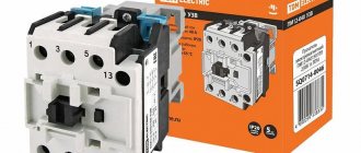
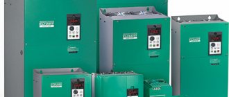
The electromagnetic starter is used for switching powerful electricity consumers, mainly in production. This article will discuss why a magnetic starter is needed, what is the principle of operation of a magnetic starter and the design of a magnetic starter. The design and principle of the starter, both for 380V and 220V circuits, are the same for a long time and have been well developed by designers.
Purpose and device
Magnetic starters are built into electrical circuits for remote starting, stopping and providing protection for electrical equipment and electric motors. The operation is based on the use of the principle of electromagnetic induction.
The basis of the design is a thermal relay and a contactor combined into one device. Such a device can also operate in a three-phase network.
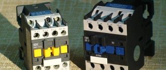
Such devices are gradually being replaced from the market by contactors. In terms of their design and technical characteristics, they are no different from starters, and they can only be distinguished by their name.
They differ from each other in the supply voltage of the magnetic coil. It comes in 24, 36, 42, 110, 220, 380 W AC. The devices are produced with a coil for direct current. Their use in an alternating current network is also possible, for which a rectifier is needed.
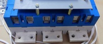
The starter design is usually divided into upper and lower parts. In the upper part there is a movable contact system combined with an arc extinguishing chamber. Also located here is the moving part of the electromagnet, mechanically connected to the power contacts. All this makes up a moving contact circuit.
At the bottom there is a coil, the second half of the electromagnet and a return spring. The return spring returns the upper half to its original state after de-energizing the coil. This is how the starter contacts break.
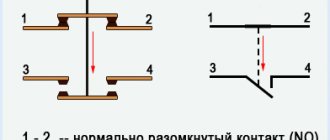
Contactors are:
- Normally closed. The contacts are closed and power is supplied constantly; shutdown occurs only after the starter is triggered.
- Normally open. The contacts are closed and power is supplied while the starter is running.
The second option is the most common.
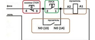
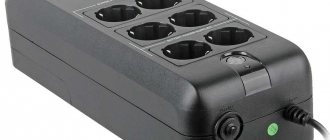
Connection via push-button post
The circuit connecting magnetic starters through a push-button station requires the use of an analog adapter. Contact blocks come with 3 or 4 outputs. When connecting, it is necessary to determine the direction of the cathode. Then the contacts are connected through the switch. To do this, use a two-channel trigger.
If you connect a device with automatic switches, then an electronic regulator is used for them. The blocks may be located on the controller. The most common devices are those with broadband connectors.
Principle of operation
The principle of operation of a magnetic starter is based on the phenomenon of electromagnetic induction. If no current passes through the coil, then there is no magnetic field in it. This causes the spring to mechanically push away the moving contacts. As soon as the power to the coil is restored, magnetic fluxes appear in it, compressing the spring and attracting the armature to the stationary part of the magnetic circuit.
Since the starter operates only under the influence of electromagnetic induction, the contacts open during power outages and when the network voltage drops by more than 60% of the nominal value. When the voltage is restored again, the contactor does not turn on on its own. To activate it, you will need to press the “Start” button.
If it is necessary to change the direction of rotation of an asynchronous motor, reversing devices are used. Reverse occurs thanks to 2 contactors, activated in turn. When the contactors are turned on simultaneously, a short circuit occurs. To eliminate such situations, the design includes a special lock.
What is the difference between magnetic starters and contactors?
Both devices are switching devices, that is, they control power networks. And more often they are installed in the electric motor starting system. In both devices, in addition to power contacts, there is at least one, and often more, which is used for the control circuit.
Otherwise they differ. Firstly, in size and weight. Starters are much more compact. At the same time, their weight is much less. For example, if you take both devices of the same rating in different hands, the contactor will be many times heavier. In addition, it should be noted that contactors that would be designed for low currents simply do not exist. They are replaced in power networks by starters.
Secondly, it's all about the design. Contactors are open type devices. They do not have a body or a lid. Therefore, the installation and connection of contactors is carried out in special rooms, which must be locked with a key. Outsiders are prohibited from entering such premises. In addition, they are well protected from precipitation. The design of contactors contains arc-extinguishing chambers. The latter are not included in the starters. But this variety is equipped with a sealed case closed with a lid. There are modifications located in metal casings. Therefore, the starters can be installed anywhere, even outdoors.
It will be interesting➡ Methods of connecting an asynchronous electric motor
Thirdly, the magnetic starter has three pairs of power contacts in its design. Therefore, their main purpose is to control electric motors. Contactors are designed to control any type of electrical circuit. Therefore, the number of power contacts in them can vary in the range of 2-4.
There are no other differences.
Varieties and types
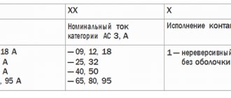
Starters manufactured according to Russian standards are divided into 7 groups depending on the rated load. The zero group can withstand a load of 6.3 A, the seventh group - 160 A.
This must be remembered when choosing magnetic starters.
The classification of foreign analogues may differ from that accepted in Russia.
It is necessary to be guided by the type of execution:
- Open. Suitable for installation in closed cabinets or places isolated from dust.
- Closed. Installed separately, in dust-free rooms.
- Dust-splash-proof. Can be installed anywhere, including outdoors. The main condition is the installation of a canopy that protects from sunlight and rain.
By type, the electromagnetic starter can be selected according to the following parameters:
- Standard versions in which voltage is supplied to the starter with further attraction of the core and activation of the contacts. In this case, depending on whether the starter is normally closed or normally open, the electrical equipment is turned on or off.
- Reversible modifications. This device is a reverse with electromagnets. This design allows you to avoid turning on 2 devices at the same time.
Installation rules
When connecting a magnetic starter, it is important to pay attention to the surface or element to which you plan to attach. Violation of installation rules can lead to false shutdowns in the future, noise effects and other troubles.
In panels, cabinets, and drawers, you must choose a flat, flat surface located in a vertical plane. The installation location must have a reliable, rigid fixation in space. It is prohibited to install electromagnetic starters in places of high heat, subject to impacts, jolts and other mechanical influences.
To reduce the mechanical load from the cable on the contact groups, the conductor must be bent into a ring or U-shape. The same technique is used for additional contacts.
Before commissioning, the structural elements must be inspected for damage. The correct connection, marking and sequence are checked.
Connection diagram for 220 V
Any electrical connection diagram contains 2 circuits, including for a single-phase network. The first is the power one, through which power is supplied. The second is a signal one. With its help, the operation of the device is monitored.
The connected contactor, thermal relay and control buttons form a single device, which is marked as a magnetic starter in the diagram. It ensures the proper functioning and safety of electric motors under various operating conditions.
Contacts for connecting the device's power are located in the upper part of the case. They are designated A1 and A2. So, for a 220 V coil, 220 V voltage is supplied. The order in which “zero” and “phase” are connected does not matter.
On the bottom of the case there are several contacts marked L1, L2, L3. The power supply for the load is connected to them. Whether it is constant or variable is not important, the main thing is the limitation of 220 V. The voltage is removed from contacts T1, T2, T3.
Protective functions of a magnetic starter
Modern magnetic starters provide protection for the electric motor from a number of such troubles:
- phase loss
- long overloads
- reducing inrush currents.
It is worth noting that protection against long-term overload is provided by a thermal relay.
In a three-phase motor, according to observations, in the presence of a symmetrical load and the absence of one of the supply phases, malfunctions instantly occur that disable it. If you install only two magnetic starters according to a certain scheme, you can provide protection against the occurrence of open-phase mode.
It will be interesting➡ Loop current method for calculating electrical circuits
When starting a three-phase electric motor, the input starting current may be several times higher than its rated value for normal operation. If such a situation occurs quite often, then various unpleasant consequences may occur, for example, overheating of the winding, and, as a result, complex breakdown. Such situations can be completely avoided with the help of a magnetic starter, so there is no doubt about the benefits of these indispensable devices.
Visual inspection
It is done in order to detect cracks, chips, and melted areas. Also, over time, the integrity of the shell in which the starter was installed may be compromised, and the presence of excess dust or crystalline salt build-ups will indicate this. It is worth understanding that the starter bounces a little when turning it on and off, which means that the fastening elements should not be cracked. Otherwise, the starter may simply fall off and turn on the load. Or turn on, for example, two phases out of three, which will certainly burn the engine.
Degree of protection
Devices with a degree of protection IP54 perform best. They can be used in damp and very dusty areas. You can install it in an open place without any problems. But if installation is carried out inside a cabinet, then it is enough to use devices with a degree of protection IP20. The higher the numerical index, the more severe the conditions under which the device can be operated - this applies to any electrical device. The following factors must also be taken into account:
- The presence of a thermal relay, with the help of which the load is switched off when the maximum current consumption is exceeded. The use of such a device is especially important when controlling electric motors.
- If there is a reverse function, then the design has two coils and six contacts. Essentially, these are a pair of starters combined in one housing.
- It is imperative to take into account the wear resistance of the device, especially if the load is turned on and off by the starter very often.
Not least in the operation of any device, including a 220V electromagnetic starter, is the human factor. Unskilled workers can break the entire control chain because they do not know how to operate the equipment correctly. If the thermal protection has tripped, it cannot be switched on immediately. And you cannot restart the engine - first you need to check whether the motor is jammed or whether there is a short circuit in the power circuit.
Usually we see this device in the form of a neat box with two buttons: “start” and “stop”. If you remove the top cover, inside you will find a switch of a rather complex design that can perform several tasks (both in turn and simultaneously).
This is an electromagnetic starter. The question arises: why create complex electrical devices if you just need to close two (or more) contacts? There are buttons with fixation, lever switches, circuit breakers, switches. Let's consider a typical application of a magnetic starter: turning on a powerful electrical installation (for example, an asynchronous electric motor).
- A powerful contact group with arc extinguishers is required; accordingly, a lot of force is required to close the contacts. A manual drive will be quite cumbersome (using a classic switch does not always fit into the aesthetics of the workplace).
- It is difficult to quickly change the operating mode with manual switches (for example, changing the direction of rotation of the motor). The magnetic starter device allows you to assemble such a connection diagram.
- Organization of protection. Any machine with an emergency shutdown is not designed to be turned on multiple times. The purpose (albeit not the main one) of a magnetic starter is not only to repeatedly switch, but also to disconnect the power circuit in case of overloads and short circuits. At the same time, it has an undeniable advantage over other switches. The shutdown is irreversible: that is, after an emergency opening of the contacts, or a momentary loss of power, the operating contacts do not return to the default “ON” position. The principle of operation of the magnetic starter implies only forced restart.
Types of contactors
In terms of equipment with protective equipment: almost all models include a thermal relay unit, which opens the circuit of additional contacts in the event of current overload. In this sense, the operating principle of a magnetic starter is no different from a circuit breaker. After an emergency shutdown and cooling of the protective group (the power circuit of the electromagnet winding is restored), the power contacts do not close. It is assumed that the operator will eliminate the cause of the emergency and restart the electrical installation.
According to the method of closing contacts, there are the following types of magnetic starters:
- Direct connection, that is, with one group of power contacts. It works according to the principle: “on” or “off”, plus protection against overload or short circuit.
- Reversible connection. An electromagnetic starter of this type is equipped with two groups of contacts, with which you can combine power lines. For example, phase rotation for an asynchronous electric motor. When different groups of contacts are closed, the electric motor shaft rotates in different directions, that is, reverse occurs.
- Working only to close power contacts, or having normally closed and normally open contact groups.
Such switches can control (in antiphase) two electrical installations. One device is connected, the second is simultaneously de-energized. - By the number of power group contacts:
- Two contact (for single-phase consumers).
- Three-contact (only phase groups are connected, the neutral is always connected). This is the most common starter model; you can connect both one and three phase electrical installations to it.
- Four or more contacts in power groups. By group we mean either a normally closed or normally open set. They are rarely used, only in special devices that operate according to a special connection scheme.
Most starters look like this:
Power contacts (three phases), additional ones are located in one plane to power the winding.
For ease of installation, additional contacts are placed on a separate platform, below and to the side.
Reversing starter
A reversible magnetic starter is a device with which you can start rotating a motor in forward and reverse directions. This is achieved by changing the phase sequence at the motor terminals. The device consists of two interlocking contactors. One of the contactors switches phases in the order A-B-C, and the other, for example, A-C-B.
Mutual interlocking is necessary so that it is impossible to accidentally turn on both contactors at the same time and create a phase-to-phase short circuit.
The reversing magnetic starter circuit looks like this:
A reversible starter can change the phase sequence on the motor by switching the voltage supplying the motor through the contactor KM1 or KM2. Please note that the phase order of these contactors is different.
When you press the “Direct Start” button, the engine starts through the KM1 contactor. In this case, the additional contact of this starter KM1.2 opens. It blocks the start of the second contactor KM2, so pressing the “Reverse start” button will lead to nothing. In order to start the engine in the opposite (reverse) direction, you must first stop it with the “Stop” button.
Auxiliary contacts for time delay starters
To increase the number of power contacts of the electromagnetic device, additional attachments are used. At the same time, the contacts in such attachments are selected taking into account the maximum current of the main ones. So, for starters of the first and second values, the current of the additional contacts must be equal to the current of the main ones or be less than the maximum value. Separately, there are additional contacts (attachments) with a delay. The main task of such set-top boxes is to wait a certain time when turning the device on and off.
Pneumatic attachments are used in control circuits for electric drives:
- With a DC voltage of 440 V and a frequency of 50 Hz;
- With an AC voltage of 660 V and a frequency of 60 Hz.
If a pneumatic PVL attachment is already installed, in order to increase the number of auxiliary contacts of the electrical control circuit, use a contact side attachment of the PKB series. The attachment is mounted using special latches on its body.