Similarities and differences between contactors and starters
Before we move on to the diagrams, let’s figure out what and how these devices can be connected.
Most often, two buttons are required - “start” and “stop”. They can be made in separate housings, or they can be a single housing. This is the so-called push-button post. Buttons can be in the same housing or in different ones
Everything is clear with individual buttons - they have two contacts. One receives power, the other leaves it. There are two groups of contacts in the post - two for each button: two for start, two for stop, each group on its own side. There is also usually a ground terminal. Nothing complicated either.
Actually, there are many options for connecting contactors; we will describe a few. The diagram for connecting a magnetic starter to a single-phase network is simpler, so let's start with it - it will be easier to understand further.
This is where you can supply power to the coil.
If you connect a cord with a plug to these contacts (as in the photo), the device will be in operation after the plug is inserted into the socket. In this case, any voltage can be applied to the power contacts L1, L2, L3, and it can be removed when the starter is triggered from contacts T1, T2 and T3, respectively.
Connecting a contactor with a 220 V coil
When connecting single-phase power to the coil, it does not matter which output is supplied with zero and which with phase. You can switch the wires. Even most often, the phase is supplied to A2, since for convenience this contact is located on the bottom side of the housing. And in some cases it is more convenient to use it and connect the “zero” to A1.
But, as you understand, this scheme for connecting a magnetic starter is not particularly convenient - you can also supply conductors directly from the power source by building in a regular switch. But there are much more interesting options.
For example, you can supply power to the coil through a time relay or a light sensor, and connect the street lighting power line to the contacts.
In this case, the phase is connected to contact L1, and zero can be taken by connecting to the corresponding coil output connector (in the photo above it is A2).
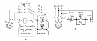
Magnetic starters are most often installed to turn on an electric motor. It is more convenient to work in this mode if there are “start” and “stop” buttons. They are connected in series to the phase supply circuit to the output of the magnetic coil. In this case, the diagram looks like the figure below. note that
Switching diagram of a magnetic starter with buttons
But with this method of switching on, the starter will operate only as long as the “start” button is held down, and this is not what is required for long-term operation of the engine. Therefore, a so-called self-catching circuit is added to the circuit. It is implemented using auxiliary contacts on the starter NO 13 and NO 14, which are connected in parallel with the start button.
Connection diagram for a magnetic starter with a 220 V coil and a self-retaining circuit
In this case, after the START button returns to its original state, power continues to flow through these closed contacts, since the magnet has already been attracted. And power is supplied until the circuit is broken by pressing the “stop” key or by triggering a thermal relay, if there is one in the circuit.
Power for the motor or any other load (phase from 220 V) is supplied to any of the contacts marked with the letter L, and is removed from the contact marked T located underneath it.
This circuit differs only in that three phases are connected to contacts L1, L2, L3 and three phases also go to the load. One of the phases is connected to the starter coil - contacts A1 or A2 (most often phase C as less loaded), the second contact is connected to the neutral wire. A jumper is also installed to maintain power supply to the coil after the START button is released.
Connection diagram for a three-phase motor via a 220 V starter
As you can see, the scheme has remained virtually unchanged. Only it added a thermal relay that will protect the engine from overheating. The assembly procedure is in the next video. The only difference is the assembly of the contact group - all phases are connected.
In some cases, it is necessary to ensure that the motor rotates in both directions. For example, for the operation of a winch, in some other cases.
A change in the direction of rotation occurs due to phase reversal - when connecting one of the starters, two phases must be swapped (for example, phases B and C).
The circuit consists of two identical starters and a button block, which includes a common “Stop” button and two “Back” and “Forward” buttons.
Reversible diagram for connecting a three-phase motor through magnetic starters
To increase safety, a thermal relay has been added, through which two phases pass, the third is supplied directly, since protection in two is more than enough.
Starters can be with a 380 V or 220 V coil (indicated in the specifications on the cover). If it is 220 V, one of the phases (any) is supplied to the coil contacts, and “zero” from the panel is supplied to the second. If the coil is 380 V, any two phases are supplied to it.
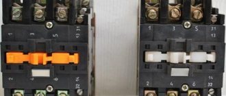
Also note that the wire from the power button (right or left) is not fed directly to the coil, but through the permanently closed contacts of another starter. Contacts KM1 and KM2 are shown next to the starter coil. Thus a blockage that prevents two contactors from being supplied with power at the same time.
Magnetic starter with a contact attachment installed on it
The following video shows a diagram of connecting a magnetic starter with reverse on an old stand using old equipment, but the general procedure is clear.
READ MORE: Is it possible to connect a screwdriver to the network via a transformer
Now about what you should pay attention to when examining the starter itself before connecting it. The most important thing is the voltage of the control coil, which is indicated either on it itself or nearby. If the inscription reads 220 V AC (or there is an AC icon next to 220), then a phase and a zero are required for the control circuit to operate.
If it is 380 V AC (the same alternating current), then the starter will be controlled by two phases. In the process of describing the operation of the control circuit, it will become clear what the difference is.
We will also need to use an additional contact of the starter, called a block contact. For most devices, it is marked with the numbers 13NO (13NO, simply 13) and 14NO (14NO, 14).
The letters NO mean “normally open”, that is, it closes only when the starter is pulled in, which can be checked with a multimeter if desired. There are starters that have normally closed additional contacts; they are not suitable for the control circuit under consideration.
Their markings vary from manufacturer to manufacturer, but there are no difficulties in identifying them. So, we attach the starter to the surface or DIN rail in the place of its permanent location, lay the power and control cables, and begin the connection.
Here, the current is supplied to the magnetic coil KM 1 through a thermal relay and terminals connected in a chain of buttons SB2 for turning on - “start” and SB1 for stopping - “stop”. When we press “start”, electric current flows to the coil. At the same time, the starter core attracts the armature, resulting in the closure of the moving power contacts, after which voltage is supplied to the load.
When “start” is released, the circuit does not open, since the KM1 block contact with closed magnetic contacts is connected parallel to this button. Thanks to this, phase voltage L3 is supplied to the coil.
When you press “stop,” the power is turned off, the moving contacts return to their original position, which leads to de-energization of the load.
The same processes occur when the thermal relay P operates - a break in the zero N supplying the coil is ensured.
Connecting to 380 V is practically no different from the first option, the only difference is in the supply voltage of the magnetic coil. In this case, power is provided using two phases L2 and L3, whereas in the first case - L3 and zero.
The diagram shows that the starter coil (5) is powered from phases L1 and L2 at a voltage of 380 V.
The principle of operation of such a circuit is as follows: After pressing the “start” button 6, through the switched on button 4 of the thermal relay, the voltage of phase L2 reaches the coil of the magnetic starter 5.
In the event of an accident, thermal relay 1 must be activated, its contact 4 is broken, the coil is turned off and the return springs bring the core to its original position. The contact group opens, relieving the voltage from the emergency area.
This circuit includes additional start and stop buttons. Both “Stop” buttons are connected in the control circuit in series, and the “Start” buttons are connected in parallel. This connection allows switching with buttons from any position.
Starters are often used to mechanically turn on heaters, lighting lines, etc. They are also used to operate engines.
MP connection diagrams differ mainly depending on which coil is located in it.
It is not difficult to turn on the starter yourself, but you can make it easier and purchase the starter already assembled, preferably with a plastic case.
In it, the structure is already assembled and the control buttons on the lid are connected. You only need to connect the electrical cables at the top and the outlet wire to the load.
MP coil
The coil is the main part of the MP; it creates an electromagnetic field when electricity passes through it, and involves an armature, 3 or 5 pairs of mobile contacts.
- a certain number of working (power) contacts through which voltage is supplied to the connected load;
- a number of auxiliary contacts - for organizing signal circuits.
MP characteristics
Starter characteristics
Depending on the type, devices are produced for emergency situations, dangerous or unprotected.
PME is a special type of MP, it is similar to regular PME, but it has a different purpose. It is used with an attachment to control electrical appliances at a distance. For example, for machine tools with asynchronous motors.
Install the MP vertically using screw clamps. The maximum deviation allowed is fifteen degrees. The instructions for use indicate that if the slope is very large, the switch may not operate properly.
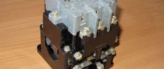
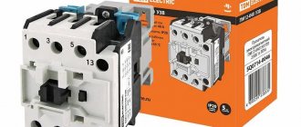
MP PML 1220
The magnetic starter PML 1220 starts and also stops the electric motor, protects it from heavy loads and from phase failure. The PML 1220 starter is irreversible. It runs an electric motor to spin the rotor in a single direction. The PML 1220 starter is enclosed in a plastic housing, has an RTP type relay, which has a protection degree of IP54, the starter has an on and off button.
Magnetic starter 3100
The magnetic starter PML 3100 220 V is a non-reversible device that does not have a thermal protection relay. It has IPOO protection. MP PML 3100 is made of a fixed part and one that moves for circuit switching. The control core makes the device operational.
Magnetic starter 2220
The PML 2220 starter is used to turn on three-phase electric motors with a squirrel-cage rotor with a voltage of up to 660 V at a distance. The starter protects devices when the voltage drops to forty to sixty percent.
The device for household use is used to start electrical equipment that is powered from a three-phase and single-phase network. With thermal relay PML 2220 they protect controlled electric motors from heavy loads over a long period and from the current that appears when a phase is broken. There is a start and stop button on the body.
Device marked 4100 at 63A
Magnetic starter PML 4100 380 V – irreversible, used for remote control of a three-phase motor, which is used in the AC-3 category. It is made from one contactor. The contacts are connected and maintained in this position for a certain time, coping with the forces of the return core. When the current stops passing through the coil or the voltage decreases, the contacts are disconnected, and they can be returned to their original position by pressing the start button.
Device marked 1100
Magnetic starter value 1100
- 1 – starter size,
- 1 – irreversible device without relay,
- 0 – IPOO protection, implementation without control buttons,
- 0 – one auxiliary closed contactor.
MP 1100 is made from a double body, a core, an active and stationary part of a magnetic wire and a contact system, which is made from active and stationary contactors. To see how the PML-1100 device is made, you need to disassemble it.
On the outer part of the magnetic starter mechanism - 1100 its main technical characteristics are written. The device core voltage is 220 V.
The coil at the starter is removed, it can also be used at 380 V.
The PML-1100 device is simply installed on a DIP rail, which has a size of thirty-five millimeters or a panel part for mounting. Dimensions of the 1100 starter: length - seventy-five millimeters, width - forty-eight millimeters, height - eighty millimeters.
Device marked 1230
A device marked 1230 is used to turn on and off asynchronous motors. Additional functions of the device - it is capable of reversing and protecting the engine from heavy loads.
Technical characteristics of PML 1230:
- has a load of 660 V,
- a device marked 1230 has a rated current of 10 A, the rest is written on the device itself,
- engine power – 5.5 kW, 380 V,
- device weight 1230 – 0.32 kg.
Device marked 2100
MP 2100 is a non-reversible device for a current of 25 A, without a relay, with IPOO protection degree. They have a current price and a two-year warranty.
The PML 2100 device starts the motor of categorical use AC-3 by connecting the stator to the network. The power plant stops if you turn off the electricity supply without introducing additional resistance into the circuit. A device marked 2100 can replace other switching devices. The PML 2100 device can replace PME 211 and PME 212.
Device marked 1501
PML 1501 – reversing starter without heat-resistant relay, current 10A. Device 1501 is used to start a squirrel-cage engine at a distance. It is assembled from two contactors - one makes it rotate in one direction, and the second in the opposite direction. PML 1501 without a thermal relay, therefore does not protect the device from heavy loads or currents that occur when one phase fails.
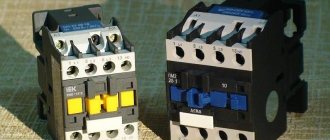
Contactors and starters - what's the difference?
The starters are made in a plastic case and are equipped with eight contacts - six for powering a three-phase motor, and two for providing it with power after the “start” button is stopped pressing. They are used both to power electric motors and devices for which this circuit is suitable.
Everything is very simple - you need to connect the lower (according to the diagram) terminal of the 380V starter coil not to zero (N), but to L2 or L3. This circuit is even more preferable, since the entire circuit with a 380V starter can be assembled without a zero at all. Three phases come in, and three phases go out to the engine, not counting the control.
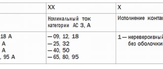
Marking of MP devices
Starter characteristics
Any starter gives users an understanding of the circumstances in which to operate this device, and also explains its main characteristics. PML models are:
- 0 — degree of protection IP00,
- 1 - IP54 protection using buttons,
- 2 - similar to IP54 unit,
- 3 - degree of protection IP54 (buttons and signal light, when turning off or starting the light diode lights up),
- 4 - degree of protection without buttons IP40,
- 5 - IP54 protection using buttons,
- 6 — degree of protection IP20.
Devices are also classified depending on the presence or absence of a thermal protection relay.
How does a starter work?
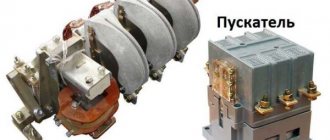
To better understand the connection diagrams of a magnetic starter, you need to understand its structure and operating principle.
The base of the starter is a magnetic circuit and an inductor. The magnetic core consists of two parts - movable and stationary. They are made in the form of the letters “Ш” with their “legs” facing each other.
The lower part is fixed to the body and is stationary, the upper part is spring-loaded and can move freely. A coil is installed in the slot in the lower part of the magnetic circuit. Depending on how the coil is wound, the rating of the contactor changes. There are coils for 12 V, 24 V, 110 V, 220 V and 380 V. On the top of the magnetic circuit there are two groups of contacts - movable and fixed.
Magnetic starter device
In the absence of power, the springs press out the upper part of the magnetic circuit, the contacts are in their original state. When voltage appears (press the start button, for example), the coil generates an electromagnetic field that attracts the upper part of the core. In this case, the contacts change their position (picture on the right).
When the voltage drops, the electromagnetic field also disappears, the springs push the moving part of the magnetic circuit up, and the contacts return to their original state. This is the principle of operation of an electromagnetic starter: when voltage is applied, the contacts close, and when voltage is lost, they open. Any voltage can be applied to the contacts and connected to them - either constant or alternating. It is important that its parameters are not greater than those declared by the manufacturer.
This is what it looks like disassembled
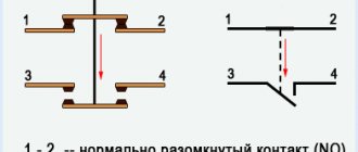
There is one more nuance: the starter contacts can be of two types: normally closed and normally open. Their operating principle is clear from the names. Normally closed contacts are switched off when triggered, while normally open contacts are closed. The second type is used to supply power; it is the most common.
Depending on its parameters, the nominal operating voltage of the device changes - from 12 to 380 volts. At the top of the magnetic circuit there are two pairs of contacts - static and dynamic.
When there is no power, a spring keeps the contacts open. When power appears, a magnetic field is induced in the coil, and the upper core is attracted to the lower one. As a result, the contacts are closed. After removing the power, the electromagnetic field also disappears, and the spring opens the contacts.
The device can operate from a direct current source, and with single- and three-phase alternating current, the main thing is that its values do not exceed the rating specified by the manufacturer.
To better understand the connection diagrams of a magnetic starter, you need to understand its structure and operating principle.
The lower part is fixed to the body and is stationary, the upper part is spring-loaded and can move freely. A coil is installed in the slot in the lower part of the magnetic circuit. Depending on how the coil is wound, the rating of the contactor changes. There are coils for 12 V, 24 V, 110 V, 220 V and 380 V. On the top of the magnetic circuit there are two groups of contacts - movable and fixed.
Price overview
You can buy a PML magnetic starter in any city; the price depends on the parameters of the selected model and its type. Also, the price list may vary depending on the specific city:
| City | The cost of the model PML-4160 DM 80A, USD. e. |
| Minsk | 8 |
| Moscow | 8 |
| St. Petersburg | 7 |
| Voronezh | 6 |
| Krasnodar | 6 |
| Rostov-on-Don | 6 |
| Chelyabinsk | 7 |
Before purchasing, be sure to check the device’s quality certificate and carefully study the operating instructions. Many manufacturing companies provide a warranty period for their products. For electrical switches, it ranges from one to three years in most cases.