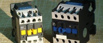
Contactors and starters - what's the difference?
Both contactors and starters are designed to close/open contacts in electrical circuits, usually power ones. Both devices are assembled on the basis of an electromagnet and can operate in DC and AC circuits of different powers - from 10 V to 440 V DC and up to 600 V AC. Have:
- a certain number of working (power) contacts through which voltage is supplied to the connected load;
- a number of auxiliary contacts - for organizing signal circuits.
So what's the difference? What is the difference between contactors and starters? First of all, they differ in the degree of protection. Contactors have powerful arc extinguishing chambers. This leads to two other differences: due to the presence of arc arresters, contactors are large in size and weight, and are also used in circuits with high currents. For low currents - up to 10 A - only starters are produced. By the way, they are not produced for high currents.
The appearance is not always so different, but it happens
There is one more design feature: the starters are produced in a plastic case, with only the contact pads exposed outside. Contactors, in most cases, do not have a housing, therefore they must be installed in protective housings or boxes that will protect against accidental contact with live parts, as well as from rain and dust.
In addition, there is some difference in purpose. The starters are designed to start asynchronous three-phase motors. Therefore, they have three pairs of power contacts - for connecting three phases, and one auxiliary one, through which power continues to flow to operate the engine after the “start” button is released. But since a similar operating algorithm is suitable for many devices, a wide variety of devices are connected through them - lighting circuits, various devices and devices.
Apparently because the “filling” and functions of both devices are almost the same, in many price lists the starters are called “small contactors”.
Push-button control station PKE-212-2
Purpose of control station PKE 212-2 U3
Push-button control stations PKE 212-2 are designed for switching electrical control circuits of alternating current voltage up to 660 V with a frequency of 50 - 60 Hz and direct current voltage up to 440 V. Push-button control posts of the PKE series are used in control panels of machine tools and automation systems. PKE 212-2 can be installed in control systems for woodworking and metalworking machines for household and industrial use, in control systems for lifting mechanisms and industrial complexes and other industrial equipment.
Technical characteristics of push-button control stations PKE 212-2
Installation method Number of pushers Shape of pushers Color of pushers Maximum voltage - alternating current with a frequency of 50-60Hz, V - direct current, V Rated current, A
| for docking to a flat surface |
| 2 |
| cylindrical |
| black red |
| 660 |
| 440 |
| 10 |
The degree of protection according to GOST 14255-69 on the pusher side is IP40, on the contact side IP40.
Climatic modification according to GOST 15150-69 and GOST 15543.1-89: U3
Overall and installation dimensions of the push-button control station PKE 212-2 U3
Design and principle of operation
To better understand the connection diagrams of a magnetic starter, you need to understand its structure and operating principle.
The base of the starter is a magnetic circuit and an inductor. The magnetic core consists of two parts - movable and stationary. They are made in the form of the letters “Ш” with their “legs” facing each other.
The lower part is fixed to the body and is stationary, the upper part is spring-loaded and can move freely. A coil is installed in the slot in the lower part of the magnetic circuit. Depending on how the coil is wound, the rating of the contactor changes. There are coils for 12 V, 24 V, 110 V, 220 V and 380 V. On the top of the magnetic circuit there are two groups of contacts - movable and fixed.
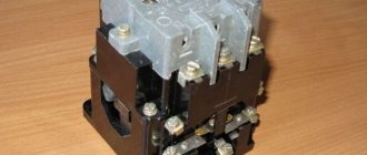
Magnetic starter device
In the absence of power, the springs press out the upper part of the magnetic circuit, the contacts are in their original state. When voltage appears (press the start button, for example), the coil generates an electromagnetic field that attracts the upper part of the core. In this case, the contacts change their position (picture on the right).
When the voltage drops, the electromagnetic field also disappears, the springs push the moving part of the magnetic circuit up, and the contacts return to their original state. This is the principle of operation of an electromagnetic starter: when voltage is applied, the contacts close, and when voltage is lost, they open. Any voltage can be applied to the contacts and connected to them - either constant or alternating. It is important that its parameters are not greater than those declared by the manufacturer.
This is what it looks like disassembled
There is one more nuance: the starter contacts can be of two types: normally closed and normally open. Their operating principle is clear from the names. Normally closed contacts are switched off when triggered, while normally open contacts are closed. The second type is used to supply power; it is the most common.
Purpose and device
Magnetic starters are built into power networks to supply and disconnect power. They can work with alternating or direct voltage. The work is based on the phenomenon of electromagnetic induction; there are working (power is supplied through them) and auxiliary (signal) contacts. For ease of use, Stop, Start, Forward, Back buttons are added to the magnetic starter switching circuits.
This is what a magnetic starter looks like
Magnetic starters can be of two types:
- With normally closed contacts. Power is supplied to the load constantly and is turned off only when the starter is triggered.
- With normally open contacts. Power is supplied only while the starter is running.
The second type is more widely used - with normally open contacts. After all, basically, devices should work for a short period of time, the rest of the time they should be at rest. Therefore, next we will consider the principle of operation of a magnetic starter with normally open contacts.
Composition and purpose of parts
The basis of a magnetic starter is an inductance coil and a magnetic circuit. The magnetic core is divided into two parts. Both of them have the shape of the letter “W”, installed in a mirror image. The lower part is stationary, its middle part is the core of the inductor. The parameters of the magnetic starter (the maximum voltage with which it can operate) depend on the inductor. There may be starters of small ratings - 12 V, 24 V, 110 V, and the most common - 220 V and 380 V.
Connection diagrams for a magnetic starter with a 220 V coil
Before we move on to the diagrams, let’s figure out what and how these devices can be connected. Most often, two buttons are required - “start” and “stop”. They can be made in separate housings, or they can be a single housing. This is the so-called push-button post.
Buttons can be in the same housing or in different ones
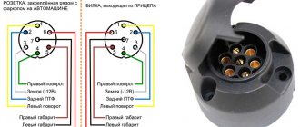
Everything is clear with individual buttons - they have two contacts. One receives power, the other leaves it. There are two groups of contacts in the post - two for each button: two for start, two for stop, each group on its own side. There is also usually a ground terminal. Nothing complicated either.
Connecting a starter with a 220 V coil to the network
Actually, there are many options for connecting contactors; we will describe a few. The diagram for connecting a magnetic starter to a single-phase network is simpler, so let's start with it - it will be easier to understand further.
Power, in this case 220 V, is supplied to the coil terminals, which are designated A1 and A2. Both of these contacts are located at the top of the case (see photo).
This is where you can supply power to the coil.
If you connect a cord with a plug to these contacts (as in the photo), the device will be in operation after the plug is inserted into the socket. In this case, any voltage can be applied to the power contacts L1, L2, L3, and it can be removed when the starter is triggered from contacts T1, T2 and T3, respectively. For example, a constant voltage from a battery can be supplied to the inputs L1 and L2, which will power some device that will need to be connected to the outputs T1 and T2.
Connecting a contactor with a 220 V coil
When connecting single-phase power to the coil, it does not matter which output is supplied with zero and which with phase. You can switch the wires. Even most often, the phase is supplied to A2, since for convenience this contact is located on the bottom side of the housing. And in some cases it is more convenient to use it and connect the “zero” to A1.
But, as you understand, this scheme for connecting a magnetic starter is not particularly convenient - you can also supply conductors directly from the power source by building in a regular switch. But there are much more interesting options. For example, you can supply power to the coil through a time relay or a light sensor, and connect the street lighting power line to the contacts. In this case, the phase is connected to contact L1, and zero can be taken by connecting to the corresponding coil output connector (in the photo above it is A2).
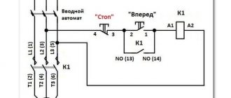
Diagram with start and stop buttons
Magnetic starters are most often installed to turn on an electric motor. It is more convenient to work in this mode if there are “start” and “stop” buttons. They are connected in series to the phase supply circuit to the output of the magnetic coil. In this case, the diagram looks like the figure below. note that
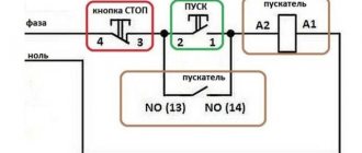
Switching diagram of a magnetic starter with buttons
But with this method of switching on, the starter will operate only as long as the “start” button is held down, and this is not what is required for long-term operation of the engine. Therefore, a so-called self-catching circuit is added to the circuit. It is implemented using auxiliary contacts on the starter NO 13 and NO 14, which are connected in parallel with the start button.
Connection diagram for a magnetic starter with a 220 V coil and a self-retaining circuit
In this case, after the START button returns to its original state, power continues to flow through these closed contacts, since the magnet has already been attracted. And power is supplied until the circuit is broken by pressing the “stop” key or by triggering a thermal relay, if there is one in the circuit.
Power for the motor or any other load (phase from 220 V) is supplied to any of the contacts marked with the letter L, and is removed from the contact marked T located underneath it.
Design features
Rice. 2 – Two-button control panel
Depending on the number of controlled electricity consumers, the posts can be two-button ("Start" and "Stop" pushers) and multi-button. In addition, when performing electrical and electrical work, single buttons are used, which the user can independently install on any control panel.
Push-button stations are mounted in a plastic or metal case that has mounting holes for installing the fittings in a place convenient for use. A separate group consists of push-button stations designed to control hoists (PKT series), beam cranes and overhead cranes with ground control.
The main functional element of the device that starts, stops or switches the modes of the electricity consumer is a push button - an electrical switching fixture with manual control.
Today, control panels use two types of pushers:
- With self-return , in which the button returns to its original state due to a return spring installed on the pusher on the bottom side.
- Pushers with position fixation (self-holding), which close the contact and hold it until pressed again.
The most common is a two-button starting valve, the design of which is shown in Fig. 2. The remote control consists of a housing 1 and a front panel 2, which are connected to each other by screws 3. The buttons are painted in different colors and control a pair of contacts located inside the housing.
In the free state of the “Start” button, its pair of contacts is open, while the “Stop” button, on the contrary, is closed. When you press the start button, its contacts close.
There are a huge number of switching schemes for various electrical systems and devices with just two buttons. However, most of them do not provide direct voltage supply to the consumer, but through the contacts of a magnetic starter, which are designed for high currents and voltages.
The housing material depends on the operating conditions and the required degree of electrical protection. Most modern push-button posts come in a metal or plastic case. However, there are also frameless fittings, in which the buttons are fixed to the panel, as well as single, frameless single-button devices.
The pushers themselves have different shapes and colors, which in fittings produced in Russia are usually reflected in their symbol.
According to their shape, pushers are divided into:
- mushroom-shaped (“GR”);
- cylindrical;
- recessed (“C”);
By pusher color:
- Stop buttons are usually colored red (“R”) or yellow (“G”);
- “Start” pushers can be black (“B”), blue (“C”), green (“Z”) or white (“B”).
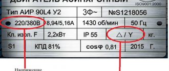
Connecting a 380 V asynchronous motor via a starter with a 220 V coil
This circuit differs only in that three phases are connected to contacts L1, L2, L3 and three phases also go to the load. One of the phases is energized to the starter coil - contacts A1 or A2. In the figure this is phase B, but most often it is phase C as it is less loaded. The second contact is connected to the neutral wire. A jumper is also installed to maintain power supply to the coil after the START button is released.
Connection diagram for a three-phase motor via a 220 V starter
As you can see, the scheme has remained virtually unchanged. Only it added a thermal relay that will protect the engine from overheating. The assembly procedure is in the next video. Only the assembly of the contact group differs - all three phases are connected.
Reversible circuit for connecting an electric motor through starters
In some cases, it is necessary to ensure that the motor rotates in both directions. For example, for the operation of a winch, in some other cases. A change in the direction of rotation occurs due to phase reversal - when connecting one of the starters, two phases must be swapped (for example, phases B and C). The circuit consists of two identical starters and a button block, which includes a common “Stop” button and two “Back” and “Forward” buttons.
Reversible diagram for connecting a three-phase motor through magnetic starters
To increase safety, a thermal relay has been added, through which two phases pass, the third is supplied directly, since protection in two is more than enough.
Starters can be with a 380 V or 220 V coil (indicated in the specifications on the cover). If it is 220 V, one of the phases (any) is supplied to the coil contacts, and “zero” from the panel is supplied to the second. If the coil is 380 V, any two phases are supplied to it.
Also note that the wire from the power button (right or left) is not fed directly to the coil, but through the permanently closed contacts of another starter. Contacts KM1 and KM2 are shown next to the starter coil. This creates an electrical interlock that prevents two contactors from being supplied with power at the same time.
Magnetic starter with a contact attachment installed on it
Since not all starters have normally closed contacts, you can take them by installing an additional block with contacts, which is also called a contact attachment. This attachment snaps into special holders; its contact groups work together with the groups of the main body.
The following video shows a diagram of connecting a magnetic starter with reverse on an old stand using old equipment, but the general procedure is clear.
MAGNETIC STARTER CONNECTION DIAGRAM
Before we begin the practical connection of the starter, let us recall a useful theory: the magnetic starter contactor is turned on by a control pulse emanating from pressing the start button, which supplies voltage to the control coil. Keeping the contactor in the on state occurs according to the self-retaining principle - when an additional contact is connected in parallel with the start button, thereby supplying voltage to the coil, as a result of which there is no need to hold the start button pressed.
Disabling the magnetic starter in this case is possible only if the control coil circuit is broken, which makes it obvious that it is necessary to use a button with a break contact. Therefore, the starter control buttons, which are called push-button posts, have two pairs of contacts - normally open (open, normally closed, NO, NO) and normally closed (closed, normally closed, NC, NC)
This universalization of all the buttons of the push-button station was made in order to anticipate possible schemes for providing instant engine reverse. It is generally accepted to call the shutdown button the word: “ Stop ” and mark it in red. The turning button is often called the start button, start button, or is designated by the words “ Start ”, “ Forward ”, “ Back ”.
If the coil is designed to operate from 220 V, then the control circuit switches the neutral. If the operating voltage of the electromagnetic coil is 380 V, then a current flows in the control circuit, “removed” from the other supply terminal of the starter.
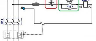
Connection diagram for a 220 V magnetic starter
Here, the current is supplied to the magnetic coil KM 1 through a thermal relay and terminals connected in a chain of buttons SB2 for turning on - “start” and SB1 for stopping - “stop”. When we press “start”, electric current flows to the coil. At the same time, the starter core attracts the armature, resulting in the closure of the moving power contacts, after which voltage is supplied to the load. When “start” is released, the circuit does not open, since the KM1 block contact with closed magnetic contacts is connected parallel to this button. Thanks to this, phase voltage L3 is supplied to the coil. When you press “stop,” the power is turned off, the moving contacts return to their original position, which leads to de-energization of the load. The same processes occur when the thermal relay P operates - a break in the zero N supplying the coil is ensured.
Connection diagram for a 380 V magnetic starter
Connecting to 380 V is practically no different from the first option, the only difference is in the supply voltage of the magnetic coil. In this case, power is provided using two phases L2 and L3, whereas in the first case - L3 and zero.
The diagram shows that the starter coil (5) is powered from phases L1 and L2 at a voltage of 380 V. Phase L1 is connected directly to it, and phase L2 is connected through button 2 “stop”, button 6 “start” and button 4 of the thermal relay, connected in series to each other. The principle of operation of such a circuit is as follows: After pressing the “start” button 6, through the switched on button 4 of the thermal relay, the voltage of phase L2 reaches the coil of the magnetic starter 5. The core is retracted, closing the contact group 7 to a certain load (electric motor M), and current is supplied, voltage 380 V. If the “start” is turned off, the circuit is not interrupted, the current passes through contact 3 - a movable block that closes when the core is retracted.
In the event of an accident, thermal relay 1 must be activated, its contact 4 is broken, the coil is turned off and the return springs bring the core to its original position. The contact group opens, relieving the voltage from the emergency area.
Fan control from two places: how to organize it?
Often, during the operation of electrical equipment, it becomes necessary to control it from two places. This function, the control method, is most often in demand in production and can be associated with the characteristics of production processes.
An example is an electric motor controlled from two places by two push-button stations. The connection diagram for an electric motor controlled from two places is not much different from the standard connection diagram for a motor controlled from one place:
As can be seen from the diagram, additional “Start” and “Stop” buttons have only been added to it (the posts are marked in red and green). Moreover, the “Stop” buttons are connected in series to the control circuit (with each other), and the “Start” buttons are connected in parallel with each other.
Thus, when you press the “Start” button from any position, the coil circuit is closed, the coil is retracted, and when the button is released, the supply voltage to the coil will flow through the KM block contact.
The control circuit is interrupted by pressing any of the “Stop” buttons connected in series.
Circuit with pass-through switches
One of the oldest and most proven schemes is the use of so-called pass-through switches. This type of electrical installation devices differs from conventional switches in that it has not two, but three contacts. In order to understand the principle of their operation, let's designate these contacts “1”, “2” and “3”.
The difference between a conventional switch and a pass-through switch
A phase wire is connected to contact number 1, from the distribution box, as in a conventional switch. When the switch is in the on position, contacts 1 and 2 are closed. Now we turn off the switch.
In a conventional switching device, in this case, contacts 1 and 2 simply open. In a pass-through switch, contacts 1 and 2 open and contacts 1 and 3 close.
Based on this feature of pass-through switches, the circuit is built.
Let's look at it in more detail:
The principle of their installation does not differ from the installation of conventional switches, so there is no point in dwelling on this issue in more detail.
Let's dwell only on the connection diagram.
Connecting a magnetic starter via a push-button post
This circuit includes additional start and stop buttons. Both “Stop” buttons are connected in the control circuit in series, and the “Start” buttons are connected in parallel. This connection allows switching with buttons from any position.
Here's another option. The circuit consists of a two-button post “Start” and “Stop” with two pairs of contacts, normally closed and open. Magnetic starter with a control coil for 220 V. The power supply for the buttons is taken from the terminal of the power contacts of the starter, number 1. The voltage approaches the “Stop” button, number 2. It passes through a normally closed contact, along the jumper to the “Start” button, number 3.
We press the “Start” button, the normally open contact number 4 closes. The voltage reaches the target, number 5, the coil is triggered, the core is retracted under the influence of the electromagnet and sets in motion the power and auxiliary contacts highlighted in dotted lines.
The auxiliary block contact 6 bypasses the contact of the “start” button 4, so that when the “Start” button is released, the starter does not turn off. The starter is turned off by pressing the “Stop” button, number 7, the voltage is removed from the control coil and the starter is turned off under the influence of the return springs.
How to connect a push-button post to a magnetic starter
A magnetic starter (contactor) is used to start and stop the motor.
It is also used to control a wide variety of loads (lighting, heating, etc.). The starter regulates the operation of devices that have remote control. The principle of its operation is based on supplying operating voltage to an electromagnetic coil. After this, its core, attached to the contacts, is retracted, which leads to the closure of the contacts. After removing the load, the contacts open again.
Connecting the push-button control station
The magnetic starter has 4 pairs of contacts that close when the electrical device is triggered. The first three take part in voltage switching. The fourth pair is designed to apply a load to the coil at the moment the start button is released. At the top there are contacts (A1, A2), to which operating voltage is supplied. To improve ease of use, A2 is duplicated below. This is the right place to access.
The connection diagram assumes the use of a conventional push-button station equipped with “Stop” and “Start” buttons. Inside the post there are both normally open and closed contacts. The functionality of the contacts varies due to the difference in connection. After pressing the button, some contacts close (in the figure below - numbered 1 and 2), while others open (numbered 3 and 4). To give you an idea, let’s illustrate the description:
First, we connect the power wires to the main terminals of the three-phase starter. We take one phase and lead it to the post for connection to terminal 4 at the base of the “Stop” button. We stretch three wires between the post and the starter. From output 3 of the “Stop” button we stretch the wire to output 2 of the “Start” button. We connect two other wires to outputs 1, 2 of the “Start” button.
Returning to the starter, we connect the neutral conductor to A1. Next, we connect the wire from the push-button station (from output 1) to A2. When the post is started, the starter will close. The released “Start” should leave the starter on, and therefore we draw a conductor from the fourth pair of contacts. To the additional terminal A2 (at the bottom) we stretch the wire from the opposite terminal of the block contact. The entire set of connections will look something like this:
As a result, at the moment of startup, the current flows to terminal A2, which closes the coil. The starter fires. After releasing the “Start” button, the current bypasses this button and also reaches the coil through the switched-on block contact. The system starts working. After pressing the “Stop” button, we interrupt the supply via a block contact and open the starter. This circuit is relevant for powering an electric motor.
Connecting the motor via starters
Irreversible magnetic starter
If it is not necessary to change the direction of rotation of the engine, then the control circuit uses two non-fixed spring-loaded buttons: one in the normal position is open - “Start”, the other is closed - “Stop”. As a rule, they are manufactured in a single dielectric housing, and one of them is red. Such buttons usually have two pairs of contact groups - one normally open, the other closed. Their type is determined during installation work visually or using a measuring device.
Installation Tips and Tricks
- Before assembling the circuit, you need to free the working area from the current and check that there is no voltage with a tester.
- Set the core voltage designation which is mentioned on it and not on the starter. It can be 220 or 380 volts. If it is 220 V, phase and zero go to the coil. Voltage marked 380 means different phases. This is an important aspect, because if connected incorrectly, the core may burn out or will not fully start the necessary contactors.
- Starter button (red) You need to take one red “Stop” button with closed contacts and one black or green button with the inscription “Start” with invariably open contacts.
- Please note that power contactors only force or stop the phases, and the zeros that come and go, conductors with grounding are always combined at the terminal block, bypassing the starter. To connect a 220 Volt core to the addition, 0 is taken from the terminal block into the design of the starter organization.
You will also need a useful device - an electrician's probe. which you can easily do yourself.
Push-button post: purpose and diagram
Push-button post
— designed for switching electrical control circuits of alternating current voltage up to 660 V, frequency 50 and 60 Hz and direct current voltage up to 440 V, and/or supplying control signals, both locally and remotely; used for remote control of various mechanisms and electrical machines. This is a simple product, consisting of a minimum number of parts, but with a very important function - issuing commands and indicating their execution.
The use of push-button posts is quite diverse and, accordingly, it has different types and designs. Example: control station for a hoist (it would be more correct, of course, to call it “control panel”) Fig.
1 . Using this type of starter, the operation of various traction mechanisms is controlled. These are mainly crane, elevator escalator, beams, etc.
However, the topic of this article will be a standard push-button station for controlling various power devices (mainly various electric motors). “Start-Stop” push-button post, I’ll immediately note that the circuit is applicable not only to magnetic starters but also to any type of relay. So, what is a “button post”? The “button post” structurally consists of a housing and two buttons “Start” and “Stop”. The appearance of buttons for push-button posts is shown in Fig. 1
.
Figure 2
shows the body of the push-button post.
- Both buttons are without fixed position.
- The “Start” button (usually green and may be backlit when turned on) has normally open contacts and is designed to turn on the CM;
- The “Stop” button (usually red) has normally closed contacts and is designed to relieve voltage from the CM;
The on-off circuit is shown in Fig. 4
. nothing complicated: when contacts SB1.1 are closed, voltage is supplied to the coil of the contactor KM1 and it is activated, while the contacts SB1.1 of the “Start” button are blocked by the normally open contacts (NO) KM1.4 of the contactor KM1. That's it, the power contacts of the KM1 contactor are closed and voltage is supplied to the power plant. You can release the “Start” button and the power unit will remain energized (will not turn off), since the KM1.4 contacts connected in parallel to the “Start” button are closed and the KM1 starter coil is constantly on. It turns out that after releasing the “Start” button, the phase continues to flow to the coil of the magnetic starter, but through its own pair of contacts KM1.4. To stop the mechanism, use the “Stop” button; when it is pressed, the contacts ST2 open, the voltage from the coil of the contactor KM1 is removed, its contacts KM1.4 open and at the same time unlocking, thereby unlocking the contacts of the “Start” button, the engine is stopped. In Figure 5, the arrow shows the movement of phase “L3” (any of the phases can be selected arbitrarily to power the magnetic contactor coil).
There may be several switching points for a particular system (for example, a ventilation system...). The connection diagram for several push-button posts is shown in Fig. 6
.
With such a switching circuit, the “executive” magnetic contactor (KM 1) can be either turned on or off from any of the “posts”; in such a circuit, it is of course desirable to backlight the start button so that the state of the system can be seen from any of the posts. As you understand, dear reader, the “Start” and “Stop” buttons provide both local (from the control and automation panel) and remote control of the magnetic starter, and therefore the load it switches. Moreover, instead of a motor, you can connect any load, for example, a powerful heating element.
Well, that's all, if you have any questions, use our email
.
Let's try to answer them competently. In the subject line of the email, write: “Irrigation systems.” PS
please do not ask questions that will be answered: “read the article carefully.”
We connect the magnetic starter via a push-button station, the “Start” and “Stop” buttons. For those who read electrical diagrams and can imagine how a circuit works in dynamics, connecting a magnetic starter will not be difficult. The site has repeatedly received requests to suggest how to connect the starter to an engine with start-stop buttons to a 220V network.
I will try to explain literally in my fingers what goes where and why. It is difficult to understand the wiring diagram at first glance. Everything will be clear when you carefully study the circuit, but not all at once, but piece by piece, element by element, asking yourself what role this contact or element plays in the circuit.
At the same time, studying the circuit, find, for example, the control coil of a magnetic starter and its contact terminals. Find power contacts on the starter - working contacts, auxiliary contacts (normally open and normally closed) necessary for blocking or bypassing contacts.
Disassemble the push-button post and understand the principle of operation. When you press a button, one contact closes and the other opens. Find the contacts in the wiring diagram and on the elements - starter and push-button post. Only after simultaneously studying the circuit and its elements will the logic and operating principle of the circuit be understood.
Magnetic starter control circuit from two and three places
Hello, dear readers and guests of the Electrician's Notes website.
After publishing an article about a magnetic starter connection diagram, I very often began to receive questions about how to control a motor from two or three places.
And it’s not surprising, because such a need can arise quite often, for example, when controlling an engine from two different rooms or in one large room, but from opposite sides or at different height levels, etc.
So I decided to write a separate article about this, so that those who come back with a similar question will not have to explain every time what needs to be connected where, but simply give a link to this article, where everything is explained in detail.
So, we have a three-phase electric motor controlled through a contactor using one push-button post. I explained in great detail how to assemble such a circuit in an article about the magnetic starter connection diagram - follow the link and get acquainted.
Here is a diagram for connecting a magnetic starter through one push-button post for the example above:
Here is a mounting version of this circuit.
Be careful! If your linear (phase-to-phase) voltage of a three-phase circuit is not 220 (V), as in my example, but 380 (V), then the circuit will look similar, only the starter coil must be at 380 (V), otherwise it will burn out.
Also, control circuits can be connected not from two phases, but from one, i.e. use any one phase and zero. In this case, the contactor coil should be rated 220 (V).
Engine control scheme from two places
I slightly modified the previous diagram by installing separate circuit breakers for the power and control circuits.
For my example with a low-power engine, this was not a critical mistake, but if you have an engine of much higher power, then this option will not be rational and in some cases not even feasible, because the cross-section of the wires for the control circuits in this case should be equal to the cross-section of the wires of the power circuits.
Let's assume that the power and control circuits are connected to one circuit breaker with a rated current of 32 (A). In this case, they must be of the same cross-section, i.e. not less than 6 sq. mm for copper. What is the point of using such a cross-section for control circuits?! The consumption currents there are quite negligible (coil, signal lamps, etc.).
What if the engine is protected by a circuit breaker with a rated current of 100 (A)? Imagine then what wire cross-sections will need to be used for control circuits. Yes, they simply simply will not fit under the terminals of coils, buttons, lamps and other low-voltage automation devices.
Therefore, it would be much more correct to install a separate machine for control circuits, for example, 10 (A) and use wires with a cross-section of at least 1.5 sq. mm for the installation of control circuits.
Now we need to add another push-button control station to this circuit. I’ll take as an example a PKE 212-2U3 post with two buttons.
As you can see, in this post all the buttons are black. I still recommend using button posts for control, in which one of the buttons is highlighted in red. It should be given the designation “Stop”. Here is an example of the same post PKE 212-2U3, only with red and black buttons. Agree that it looks much clearer.
The whole point of changing the circuit comes down to the fact that we need to connect the “Stop” buttons of both button posts in series, and the “Start” (“Forward”) buttons in parallel.
Let's call the buttons at post No. 1 “Start-1” and “Stop-1”, and at post No. 2 “Start-2” and “Stop-2”.
Now from terminal (3) of the normally closed contact of the “Stop-1” button (post No. 1) we make a jumper to terminal (4) of the normally closed contact of the “Stop-2” button (post No. 2).
Then we make two jumpers from terminal (3) of the normally closed contact of the “Stop-2” button (post No. 2). One jumper to terminal (2) of the normally open contact of the “Start-1” button (post No. 1).
And the second jumper to terminal (2) of the normally open contact of the “Start-2” button (post No. 2).
And now it remains to make one more jumper from terminal (1) of the normally open contact of the “Start-2” button (post No. 2) to terminal (1) of the normally open contact of the “Start-1” button (post No. 1). Thus, we connected the “Start-1” and “Start-2” buttons in parallel to each other.
Ready.
Here is the assembled circuit and its installation version.
Now you can control the contactor coil, as well as the motor itself, from any station closest to you. For example, you can turn on the engine from post No. 1, and turn it off from post No. 2, and vice versa.
I suggest you watch how to assemble an engine control circuit from two places and the principle of its operation in my video:
Errors that may occur when connecting
If you mix it up and connect the “Stop” buttons not in series with each other, but in parallel, then you can start the engine from any position, but it’s unlikely to stop it, because in this case, you will need to press both “Stop” buttons at once.
And vice versa, if the “Stop” buttons are assembled correctly (sequentially), and the “Start” buttons are assembled sequentially, then the engine will not be able to start, because in this case, to start you will need to press two “Start” buttons simultaneously.
Engine control scheme from three places
If you need to control the engine from three places, then another push-button station will be added to the circuit. And then everything is similar: all three “Stop” buttons must be connected in series, and all three “Start” buttons must be connected in parallel to each other.
Installation diagram.
If you need to reverse start an asynchronous motor from several places, then the meaning remains the same, only in addition to the “Stop” and “Start” (“Forward”) buttons, another “Back” button will be added to the circuit, which will need to be connected in parallel the “Back” button of another control station.
I recommend: at control stations, in addition to buttons, provide a light indication of the presence of voltage in the control circuits (“Network”) and the state of the engine (“Moving forward” and “Moving backward”), for example, using the same LED lamps SKL, about the advantages and disadvantages which I told you in detail not so long ago. This is roughly what it will look like. Agree that it looks clear and intuitive, especially when the motor and contactor are located far from the control stations.
As you may have guessed, the number of push-button stations is not limited to two or three, and engine control can be carried out from a larger number of places - it all depends on the specific requirements and conditions of the workplace.
By the way, instead of a motor, you can connect any load, for example, lighting, but I will tell you about this in my next articles.
PS That's probably all. Thank you for your attention. Any questions - just ask?!
If the article was useful to you, then share it with your friends:
Read Full Article
dokladinf.ru