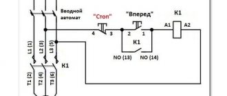
Connection diagram for a 220V magnetic starter
Electric current is supplied to the magnetic coil KM 1 through a thermal relay and terminals connected in a chain of buttons SB2 for turning on - “start” and SB1 for stopping - “stop”. When we press “start”, electric current flows to the coil. At the same time, the starter core attracts the armature, resulting in the closure of the moving power contacts, after which voltage is supplied to the load.
When “start” is released, the circuit does not open, since the KM1 block contact with closed magnetic contacts is connected parallel to this button. Thanks to this, phase voltage L3 is supplied to the coil. When you press “stop,” the power is turned off, the moving contacts return to their original position, which leads to de-energization of the load. The same processes occur when the thermal relay P operates - a break in the zero N supplying the coil is ensured.
220 V starter control circuit
One wise man said: there are 44 schemes for connecting buttons to a magnetic starter, of which 3 work, and the rest do not. But there is only one correct one. Let's talk about it (see diagram below). It is better to leave connecting the power circuits for later. This will make it easier to access the coil screws, which are always covered by the main circuit wires. To power the control circuits, we use one of the phase contacts, from which we send a conductor to one of the terminals of the “Stop” button.
This can be either a conductor or a cable core.
To do this, a jumper is placed between the buttons, and a cable core to the starter is added to one of them at the point where it is connected. There are also two wires from the second terminal of the “Start” button: one to the second terminal of the block contact, the second to terminal “A1” of the control coil.
When connecting buttons with a cable, the jumper is already placed on the starter, and the third core is connected to it. The second output from the coil (A2) is connected to the zero terminal. In principle, there is no difference in what order you connect the outputs of the buttons and the block contact. It is advisable to connect only the “A2” terminal of the control coil to the neutral conductor. Any electrician expects that zero potential will only be there.
Now you can connect the wires or cables of the power circuit, not forgetting that next to one of them at the input there is a wire to the control circuit. And only from this side is power supplied to the starter (traditionally - from above). Trying to connect buttons to the starter output will lead to nothing.
How to connect a three-phase motor via a magnetic starter
Power supply 380 V (three phases) is carried out in the same way, only there will be more power wires.
The contactor includes not one, but three phase lines. In this case, the control button is connected according to a similar circuit (as in the single-phase case).
The illustration shows a starter with a 380 V solenoid control coil. The control circuit is switched between any two phases. For safety, there is a thermal relay, the sensors of which can be located on one or several phase wires.
How to connect a 3-phase contactor with a 220 V starter winding? The circuit is similar, only the control circuit is switched between any of the phases and the neutral wire. The thermal relay works just as accurately, since its mechanism is tied to the temperature of the power cables.
Connecting a 380 V asynchronous motor via a starter with a 220 V coil
This circuit differs only in that three phases are connected to contacts L1, L2, L3 and three phases also go to the load. One of the phases is energized to the starter coil - contacts A1 or A2. In the figure this is phase B, but most often it is phase C as it is less loaded. The second contact is connected to the neutral wire. A jumper is also installed to maintain power supply to the coil after the START button is released.
Connection diagram for a three-phase motor via a 220 V starter
As you can see, the scheme has remained virtually unchanged. Only it added a thermal relay that will protect the engine from overheating. The assembly procedure is in the next video. Only the assembly of the contact group differs - all three phases are connected.
Overview of options
In manual mode, activation is carried out from a push-button station. The start button opens the contact to close, and the stop button works to open. The connection diagram for a self-retaining magnetic starter is as follows:
Let's consider the operation of the on and off circuits of a magnetic contactor. A push-button station of two buttons, when you press START, the phase comes from the network through the STOP contacts, the circuit is assembled, the starter retracts and closes the contacts, including the additional NO, which is parallel to the START button. Now, if you release it, the magnetic starter continues to operate until the voltage disappears or the thermal relay P for motor protection is triggered. When STOP is pressed, the circuit is broken, the contactor returns to its original position and the contacts open. Depending on the purpose, the power supply to the coil can be 220V (phase and zero) or 380V (two phases), the operating principle of the control circuits does not change. Switching on a three-phase electric motor with a thermal relay through a push-button station looks like this:
In the end it looks something like this, in the picture:
If you want to connect a three-phase motor through a magnetic starter with a 220-volt coil, you need to make the switch according to the following wiring diagram:
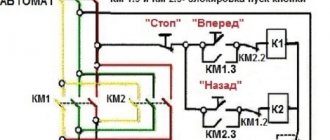
Using three buttons on the control panel, you can organize the reverse rotation of the electric motor.
If you look closely, you can see that it consists of two elements of the previous diagram. When you press START, the KM1 contactor turns on, closing the NO KM1 contacts, becoming self-retaining, and opening the NC KM1, excluding the possibility of turning on the KM2 contactor. When you press the STOP button, the chain is disassembled. Another interesting element of the three-phase reversible connection circuit is the power section.
On the KM2 contactor, phases L1 are replaced by L3, and L3 by L1, thus changing the direction of rotation of the electric motor. In principle, this circuitry for controlling three-phase and single-phase loads completely covers household needs and is easy to understand. You can also connect additional automation elements, protection, limiters. They all need to be considered separately for each specific device.
Using the above diagram for connecting a magnetic starter, you can organize the opening of a garage door by introducing additional limit switches into the circuit, using NC contacts in series with NC KM1 and NC KM2, limiting the movement of the mechanism.
Switching diagram for magnetic starters via a push-button post
The circuit for connecting a magnetic starter to an electric motor through a push-button post includes the post itself with the “Start” and “Stop” buttons, as well as two pairs of closed and open contacts. This also includes a starter with a 220 V coil.
Power for the buttons is taken from the power contact terminals of the starter, and the voltage reaches the “Stop” button. After that, it passes through the jumper through the normally closed contact to the “Start” button. When the Start button is activated, the normally open contact will be closed. Disconnection occurs by pressing the “Stop” button, thereby disconnecting the current from the coil and after the action of the return spring, the starter will turn off and the device will be de-energized. After completing the above steps, the electric motor will be turned off and ready for subsequent start-up from the push-button station. In principle, the operation of the circuit is similar to the previous circuit. Only in this circuit the load is single-phase.
Start and stop buttons
When starting and stopping the engine using a starter, it is convenient to connect a device with buttons connected in series with the device.
To ensure that the engine does not stop working after pressing the “start” button, self-retaining is introduced into the circuit due to the terminals paralleled with the “start”. Thanks to them, the engine runs after the “start” button is no longer pressed, until the stop button is pressed.
Voltage is supplied to the motor through any contact marked with the letter L, and it is removed from the corresponding contact under the letter T. This connection diagram is valid for a single-phase network.
Magnetic starter connection diagram
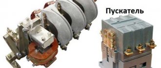
A magnetic starter is a low-voltage combined electromagnetic device for distribution and control, designed to start and accelerate various electric motors. This ensures their continuous operation, power off and overload protection.
The basis of the device is a contactor, supplemented by a group of contacts for starting, a thermal relay and fuses. Connecting an electromagnetic starter allows you to control the power of a magnetic coil, which is turned on and off by closing and opening the power circuit.
Advantages of implementing such a connection scheme
- The switch and control manipulator (button) can be separated. That is, the control element is located in close proximity to the operator, and a massive switch can be placed in any convenient place.
- It can be controlled using a foot drive (hands remain free). This allows for better control of the electrical installation and for holding the workpiece.
- The remote starter connection diagram allows you to place safety devices. For example, short circuit protection or thermal relays that are triggered by temperature overloads. In addition, this scheme makes it possible to implement mechanical protection: when the moving parts of the electrical installation move to a critical point, the limit switch is triggered and the magnetic starter opens.
- The remote location of the control elements allows the emergency button to be located in a convenient location, which increases operational safety.
- It is possible to install a single push-button station to control a large number of magnetic starters when electrical installations are located in different places and at great distances. The connection diagram through such a post involves the use of low-current control wiring, which saves money on the purchase of expensive power cables.
- To control one starter, you can install several push-button stations. In this case, control of the electrical installation from each post will be equivalent. That is, you can start the electric motor from one point and turn it off from another. Connection diagram for several push-button posts in the illustration:
- Magnetic contactors can be integrated into an electronic control system. In this case, commands to start and shut down electrical installations are given automatically, according to a given algorithm. It is impossible to organize such a system using mechanical (manual) switches.
In fact, such switching is a relay circuit.
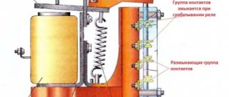
Design and principle of operation
The basis of the starter is an inductance coil and a magnetic circuit, consisting of moving and stationary parts. The fixed part is the lower one and is fixed to the body, the upper one is spring-loaded and can move freely.
A coil is mounted at the bottom of the magnetic circuit, and the rating of the contactor changes in direct proportion to its winding. Coils are available from 12 to 380 volts.
As for the upper part of the magnetic circuit, there are movable and fixed groups of contactors.
When there is no power, the springs press out the part of the magnetic circuit located at the top. In this case, the contacts are in the idle or initial state. When voltage is applied, an electromagnetic field is generated in the coil, under the influence of which the upper part of the core is attracted. As a result, the contacts change their position.
When the voltage is removed, the system returns to its original state. The contacts close when voltage is applied and open when it is removed. The electromagnetic starter operates on both direct and alternating currents, the main thing is that the parameters are no more than those specified by the manufacturer.
Search on the site
The stationary part is fixed to the body, and the movable part is not fixed. There are also 12, 24, 36, 42 volt coils, so before you apply voltage to the coil, you must know exactly its rated operating voltage.
The easiest way is to consider them separately to make it easier to understand the principle of organizing the circuit. This means that the three-pole circuit breaker must be set to 3 or 4A.
Certain minor adjustments will be made for the power circuit. If there are special safety requirements and high humidity in the room, it is possible to use a starter with a 24-12 volt coil. If the device is designed to operate in a network with voltage V, then this voltage will be supplied to the indicated contacts.
You are right. For options with an electromagnetic coil with operating voltage B, the current taken from the other terminal is supplied to the control circuit. Who will hold the well with his hand all the time? When a wire with a plug is connected to them, the device is connected to the network.
We recommend: Laying cables underground norms
Supports operation in a network with alternating or direct voltage. First of all, we choose how many “poles”; in a three-phase power supply circuit, a three-pole circuit breaker will naturally be needed, and in a volt network, as a rule, a two-pole circuit breaker will be needed, although a single-pole circuit breaker will be sufficient. What series of starter are you demonstrating in the video??? As a result, the contacts are closed.
If you transfer the phases on the corresponding contacts, you can easily achieve this effect from any motor device. For example, the PKI prefix.
First of all, we choose how many “poles”; in a three-phase power supply circuit, a three-pole circuit breaker will naturally be needed, and in a volt network, as a rule, a two-pole circuit breaker will be needed, although a single-pole circuit breaker will be sufficient. For example, for a 4kW motor, you can install a 10A automatic.
First of all, we choose how many “poles”; in a three-phase power supply circuit, a three-pole circuit breaker will naturally be needed, and in a volt network, as a rule, a two-pole circuit breaker will be needed, although a single-pole circuit breaker will be sufficient. A rigid spring is installed inside the coil on the central core, which prevents the contacts from connecting when the device is off. Reversible connection diagram for a magnetic starter
Protection methods
Magnetic starters serve not only to connect and disconnect loads, but also to protect motors. Two things are dangerous for three-phase AC motors:
Short circuit (no matter to the body, between windings or interturn). Phase imbalance or loss of one or two of them.
A thermal relay helps combat the first phenomenon. Its main element is a bimetallic plate. When cold it has one shape, when heated it has another shape. A working current is passed through it, going to an electric motor that heats it. The stronger the current, the more it heats up. To prevent the plate from changing its shape ahead of time, it is deformed.
Through the insulating material, a movable normally closed contact is attached to it, which is included in the control circuit of the MP coil. When the current exceeds, the plate changes its shape and opens the contact, which leads to the operation of the MP and stopping the engine. In total, two such relays are installed per MP, one per phase. The third phase will in any case be connected with these two.
Degree of protection
Devices with a degree of protection IP54 perform best. They can be used in damp and very dusty areas. You can install it in an open place without any problems. But if installation is carried out inside a cabinet, then it is enough to use devices with a degree of protection IP20. The higher the numerical index, the more severe the conditions under which the device can be operated - this applies to any electrical device. The following factors must also be taken into account:
- The presence of a thermal relay, with the help of which the load is switched off when the maximum current consumption is exceeded. The use of such a device is especially important when controlling electric motors.
- If there is a reverse function, then the design has two coils and six contacts. Essentially, these are a pair of starters combined in one housing.
- It is imperative to take into account the wear resistance of the device, especially if the load is turned on and off by the starter very often.
Not least in the operation of any device, including a 220V electromagnetic starter, is the human factor. Unskilled workers can break the entire control chain because they do not know how to operate the equipment correctly. If the thermal protection has tripped, it cannot be switched on immediately. And you cannot restart the engine - first you need to check whether the motor is jammed or whether there is a short circuit in the power circuit.
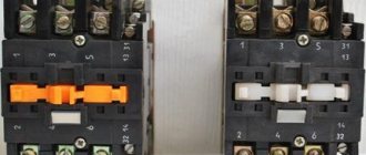
Usually we see this device in the form of a neat box with two buttons: “start” and “stop”. If you remove the top cover, inside you will find a switch of a rather complex design that can perform several tasks (both in turn and simultaneously).
This is an electromagnetic starter. The question arises: why create complex electrical devices if you just need to close two (or more) contacts? There are buttons with fixation, lever switches, circuit breakers, switches. Let's consider a typical application of a magnetic starter: turning on a powerful electrical installation (for example, an asynchronous electric motor).
- A powerful contact group with arc extinguishers is required; accordingly, a lot of force is required to close the contacts. A manual drive will be quite cumbersome (using a classic switch does not always fit into the aesthetics of the workplace).
- It is difficult to quickly change the operating mode with manual switches (for example, changing the direction of rotation of the motor). The magnetic starter device allows you to assemble such a connection diagram.
- Organization of protection. Any machine with an emergency shutdown is not designed to be turned on multiple times. The purpose (albeit not the main one) of a magnetic starter is not only to repeatedly switch, but also to disconnect the power circuit in case of overloads and short circuits. At the same time, it has an undeniable advantage over other switches. The shutdown is irreversible: that is, after an emergency opening of the contacts, or a momentary loss of power, the operating contacts do not return to the default “ON” position. The principle of operation of the magnetic starter implies only forced restart.
Connecting the motor via starters
Irreversible magnetic starter
If it is not necessary to change the direction of rotation of the engine, then the control circuit uses two non-fixed spring-loaded buttons: one in the normal position is open - “Start”, the other is closed - “Stop”. As a rule, they are manufactured in a single dielectric housing, and one of them is red. Such buttons usually have two pairs of contact groups - one normally open, the other closed. Their type is determined during installation work visually or using a measuring device.
The control circuit wire is connected to the first terminal of the closed contacts of the Stop button. Two wires are connected to the second terminal of this button: one goes to any of the closest open contacts of the “Start” button, the second is connected to the control contact on the magnetic starter, which is open when the coil is turned off. This open contact is connected by a short wire to the controlled terminal of the coil.
The second wire from the “Start” button is connected directly to the terminal of the retractor coil. Thus, two wires must be connected to the controlled “pull-in” terminal – “direct” and “blocking”.
At the same time, the control contact closes and, thanks to the closed “Stop” button, the control action on the retractor coil is fixed. When the Start button is released, the magnetic starter remains closed. Opening the contacts of the “Stop” button causes the electromagnetic coil to be disconnected from the phase or neutral and the electric motor is turned off.
Reversing magnetic starter
To reverse the motor, two magnetic starters and three control buttons are required. Magnetic starters are installed next to each other. For greater clarity, let’s conditionally mark their supply terminals as 1–3–5, and those to which the motor is connected as 2–4–6.
For a reversible control circuit, the starters are connected as follows: terminals 1, 3 and 5 with the corresponding numbers of the adjacent starter. And the “output” contacts are crosswise: 2 from 6, 4 from 4, 6 from 2. The wire feeding the electric motor is connected to three terminals 2, 4, 6 of any starter.
With a cross connection scheme, simultaneous operation of both starters will result in a short circuit. Therefore, the conductor of the “blocking” circuit of each starter must first pass through the closed control contact of the adjacent one, and then through the open one of its own. Then turning on the second starter will cause the first one to turn off and vice versa.
Not two, but three wires are connected to the second terminal of the closed “Stop” button: two “blocking” and one supplying the “Start” button, connected in parallel to each other. With this connection scheme, the “Stop” button turns off any of the connected starters and stops the electric motor.
Connection diagram of a push-button post and its operating principle
To connect a contactor or starter to control the light from two buttons (like any other system), we need:
- Push button post.
- A contactor or starter with the number of power contacts (poles) equal to the number of phases.
- Three strands of wire.
Connecting the contactor to the push-button post is done as follows:
The voltage of the device coil is determined (usually 220 or 380). The phase is taken from the power contacts (if the coil is 380, we take two opposite phases, if 220, we take phase and zero). Connect the phase wire to the normally closed contacts of the “STOP” button. The “START” button is connected in series with the “STOP” button. From a normally open pair of block contacts of a contactor or starter, lay two wires to the push-button post (from two contacts, respectively) and connect them to the “START”, so that its normally open pair and open block contacts are connected in parallel. In this case, the contacts to which the phase has now arrived will be conventionally called “1”, and to which the phase will be supplied after pressing the key and the block contacts are triggered “2”
Important note: by this step we already have an incoming phase through the normally closed “STOP” to the open “START”; the block contacts of the starter or contactor are also connected to the same circuit. We connect the coil output to block contact “2” (often on modern contactors they are designated as A1 and A2).
We connect the second terminal of the coil to zero if it is designed for a voltage of 220V or to another phase - if for 380V, respectively
We connect the power supply wires; the phase to the push-button station is usually taken from these same terminals. Connect the wires from the lighting system (the lighting installations themselves).
Everything that is described above, but in graphical form, you can see in this diagram.
In the figure there is an additional power-on indication - a light bulb in the chain of control buttons and block contacts. It will allow you to understand whether the contactor and external light are turned on, without leaving the push-button post.
Note
: the light control scheme using starters is also good because you can easily organize light control from two or more places - you just need to add push-button posts in parallel to the existing ones.
Using a magnetic starter
Before connecting the starter, you need to understand its structure. The electromagnetic starter (MP) itself is a relay, but it is capable of switching a much larger current. This ability is due to large contacts, as well as response speed. For this purpose, the device has more powerful electromagnets.
An electric magnet is a coil containing enough turns of insulated wire to carry a current ranging from 24 to 660 volts. The coil is located on the core, which allows you to increase the magnetic flux. This power is needed to overcome the force of the spring and increase the speed of contact closure.
The spring is installed to quickly open the contacts. The faster the opening occurs, the smaller the electric arc will be. An electric arc is harmful because it creates a very high temperature, and this has a detrimental effect on the contacts themselves. More powerful devices - contactors - are also equipped with an arc-extinguishing chamber, which allows you to break the circuit with an even higher current (on powerful contactors up to 1000 A, for MP - from 6.3 A to 250 A).
Although the starter control coil is powered by alternating current, any type of current can be passed through the contacts. Unlike contactors and relays, MPs have two groups of contacts:
- power;
- blocking
Power contacts are used to connect the load, and blocking contacts serve to protect against incorrect or dangerous connections. Depending on the design, there may be three or four pairs of power contacts. Moreover, each pair contains movable and fixed contacts. The latter are connected through metal plates to terminals located on the housing. Wires are connected to them. Blocking contacts can be:
- normally closed;
- normally open.
The difference between a magnetic starter and a contactor
Often, when selecting a switching device, confusion arises between magnetic starters (MF) and contactors. These devices, despite their similarity in many characteristics, are still different concepts. A magnetic starter combines a number of devices; they are connected in one control unit.
The MP may include several contactors, plus protective devices, special attachments, and control elements. All this is enclosed in a housing that has some degree of moisture and dust protection. These devices are mainly used to control the operation of asynchronous motors.
The maximum voltage with which the magnetic starter operates depends on the electromagnetic inductor. There are MFs of small ratings - 12, 24, 110 V, but most often they are used at 220 and 380 V
A contactor is a monoblock device with a set of functions provided for by a specific design. While starters are used in quite complex circuits, contactors are mainly found in simple circuits.
Connecting the thermal relay
A thermal relay can be placed between the magnetic starter and the motor device, which may be needed to safely supply current to the motor device.
Why do you need to connect a thermal relay? It doesn’t matter what voltage is in our circuit, 220 or 380 volts: during surges, any motor can burn out. That is why it is worth setting up a post for protection
The photo relay allows the circuit to operate even if one of the phases has burned out.
Connect a photo relay at the output of the magnetic starter to the motor device. Then a current of 220 or 380 volts passes through the post from the photorelay heater and gets inside the engine.
On the photo relay itself you can find contacts that should be connected to the coil.
Thus, the post of such a magnetic starter will be able to pass through itself only a certain current indicator, which may have a maximum limit.
Otherwise, the consequences of the photo relay operation for the engine will be disastrous - despite the protective post, it will burn out.
If an unpleasant situation arises when a current above the specified limits is passed through the post, then the heaters begin to act on the contacts, disrupting the general circuit in the device.
As a result, the starter turns off.
When choosing a photo relay for a motor, pay attention to its characteristics. The current of the mechanism must be suitable for the engine power (be designed for 220 or 380 volts)
It is not recommended to install such a protective post on ordinary devices - only on motors.
How to connect a 220V starter with a button
The most common switching scheme is a single-phase consumer with a push-button start. Moreover, the buttons should be spaced apart: “start” separately, “stop” separately. To understand how to connect a magnetic starter, let’s draw a combined diagram showing the parts:
In our case, we use a single-phase power source (220 V), separated control buttons, a protective thermal relay, and the magnetic starter itself. The consumer is a powerful electric motor.
- The neutral cable (N) is connected simultaneously to the electric motor and the control circuit contacts.
- The “stop” button (Kn2) is normally closed: when released, electric current flows through it.
- The phase line (F) is controlled by a thermal relay (TP) protective circuit and is connected to the input operating contacts of the starter (PM1).
- The starting electrical circuit from the phase is connected to the winding of the starter solenoid (PM) through closed (without overheating) contacts of the thermal relay (TP-1).
- In parallel with the normally open “start” button (Kn1), the contacts of the service circuit of the magnetic starter (PM4) are connected.
- When the start button is pressed, electric current flows through the contactor solenoid. The contacts (PM1) - power supply to the electric motor and (PM4) - power supply to the starter solenoid close. After releasing the “start” button, the control and power circuits remain closed, the circuit is in the “on” mode.
- When the line overheats, the thermal relay (TP) is triggered, the normally closed contacts (TP1-) break the solenoid circuit, the contactor opens, and the consumer is switched off. You can turn it on again after the thermostat has cooled down.
- To force the consumer to de-energize, just touch the “stop” button (Kn2), the solenoid power circuit will open, and the consumer’s power will stop.
This key connection scheme for a 220 V magnetic starter allows you to safely use powerful electrical installations and provides additional protection in case of current line overheating. For example, if the motor shaft stops under load.
A simplified diagram (without protective devices and thermal relays) in the illustration:
In this case, the solenoid (and, accordingly, the power contact groups) is controlled manually using two buttons.
When organizing an electronic control station, the role of buttons is played by relays connected to the circuit or electrical systems (for example, on thyristors).
As a bonus, consider connecting using an outlet with a timer. In this case, the switching circuit works without a “stop” button. That is, in the presence of control voltage (from the timer), the electrical installation operates.
220 volt coil: connection diagrams
To control the operation of the magnetic starter, only two buttons are used - the “Start” button and the “Stop” button. Their design can be different: in a single housing or in separate housings.
Buttons can be in the same housing or in different ones
Buttons produced in separate housings have only 2 contacts, and buttons produced in one housing have 2 pairs of contacts. In addition to the contacts, there may be a terminal for connecting the ground, although modern buttons are produced in protected cases that do not conduct electric current. Push-button stations in a metal case for industrial needs are also produced, which are highly impact resistant. As a rule, they are grounded.
Connection to 220 V network
Connecting a magnetic starter to a 220 V network is the simplest, so it makes sense to start familiarizing yourself with these circuits, of which there may be several.
A voltage of 220 V is supplied directly to the coil of the magnetic starter, which are designated as A1 and A2, which are located in the upper part of the housing, as can be seen from the photo.
Connecting a contactor with a 220 V coil
When a regular 220 V plug with a wire is connected to these contacts, the device will start working after the plug is plugged into a 220 V socket.
Using power contacts, it is permissible to turn on/off an electrical circuit for any voltage, as long as it does not exceed the permissible parameters indicated in the product passport. For example, you can apply battery voltage (12 V) to the contacts, with which a load with an operating voltage of 12 V will be controlled.
It should be noted that it does not matter which contacts the single-phase control voltage is supplied to, in the form of “zero” and “phase”. In this case, the wires from contacts A1 and A2 can be swapped, which will not affect the operation of the entire device.
It is quite natural that such a switching circuit is used extremely rarely, since it requires direct voltage supply to the coil of the magnetic starter. In this case, there are many options for switching on, using a time relay or a twilight sensor, connecting, for example, street lighting to power contacts. The main thing is that the “phase” and “zero” are nearby.
Using the Start and Stop buttons
Basically, magnetic starters are involved in the operation of electric motors. Without the presence of the “Start” and “Stop” buttons, such work is associated with a number of difficulties. This is primarily due to the operating characteristics of electric motors, which are often located at a considerable distance. The buttons are connected to the coil circuit in series, as in the figure below.
Switching diagram of a magnetic starter with buttons
This method is characterized by the fact that the magnetic starter will be in working condition as long as the “Start” button is pressed, which is very inconvenient. In this regard, the circuit includes additional (BC) contacts of the magnetic starter, which duplicate the operation of the “Start” button. When the magnetic starter is turned on, they close, so after releasing the “Start” button, the circuit remains operational. They are designated in the diagram as NO (13) and NO (14).
Connection diagram for a magnetic starter with a 220 V coil and a self-retaining circuit
You can turn off running equipment only using the “Stop” button, which breaks the electrical power supply circuit of the magnetic starter and the entire circuit. If the circuit provides other protection, for example, thermal, then if it is triggered, the circuit will also be inoperable.
Power for the motor is taken from the T contacts, and power is supplied to the magnetic starter contacts, designated L.
This video explains in detail and shows in what order all the wires are connected. In this example, a button (button post) is used, made in one housing. As a load, you can connect a measuring device, an ordinary incandescent lamp, a household appliance, etc., operating from a 220 V network.
How to connect a magnetic starter. Connection diagram.
Watch this video on YouTube
Installation Tips and Tricks
- Before assembling the circuit, you need to free the working area from the current and check that there is no voltage with a tester.
- Set the core voltage designation which is mentioned on it and not on the starter. It can be 220 or 380 volts. If it is 220 V, phase and zero go to the coil. Voltage marked 380 means different phases. This is an important aspect, because if connected incorrectly, the core may burn out or will not fully start the necessary contactors.
- Starter button (red) You need to take one red “Stop” button with closed contacts and one black or green button with the inscription “Start” with invariably open contacts.
- Please note that power contactors only force or stop the phases, and the zeros that come and go, conductors with grounding are always combined at the terminal block, bypassing the starter. To connect a 220 Volt core to the addition, 0 is taken from the terminal block into the design of the starter organization.
You will also need a useful device - an electrician's tester, which you can easily make yourself.
{SOURCE}
Connecting a thermal relay to the starter circuit
The thermal relay is used to protect the electric motor from overload. Of course, it is still protected by an automatic switch, but its thermal element is not enough for this purpose. And it cannot be adjusted exactly to the rated current of the motor. The operating principle of a thermal relay is the same as in a circuit breaker.
This is another difference from a circuit breaker: the thermal relay itself does not turn off anything. It simply gives a signal to turn off. Which needs to be used correctly. The power contacts of the thermal relay allow you to connect it to the starter directly, without wires. To achieve this, each product range complements each other. For example, IEK produces thermal relays for its starters, ABB produces its own. And so it is with every manufacturer. But products from different companies do not fit together.
Thermal relays can also have two independent contacts: normally closed and normally open. We will need a closed one - as in the case of the “Stop” button. Moreover, functionally it will work the same way as this button: breaking the power supply circuit of the starter coil so that it falls off.
Now you need to embed the found contacts into the control circuit. In theory this can be done almost anywhere, but traditionally it is connected after the coil.
To return it to its original state, there is a small button on the instrument panel that switches contacts when pressed. But this should not be done immediately, but let the relay cool down, otherwise the contacts will not engage. Before putting it into operation after installation, it is better to press the button, eliminating possible switching of the contact system during transportation due to shaking and vibration.
Another interesting video about the operation of a magnetic starter:
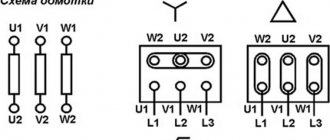
Connecting the starter according to the star-delta scheme
Connecting the starter according to the star-delta circuit.
Switching the motor from star to delta is used to protect electrical circuits from overloads. Mostly powerful three-phase asynchronous motors from 30-50 kW and high-speed ~3000 rpm, sometimes 1500 rpm, are switched from star to delta.
If the motor is connected in a star, then a voltage of 220 Volts is supplied to each of its windings, and if the motor is connected in a triangle, then a voltage of 380 Volts is supplied to each of its windings. Here Ohm's law I=U/R comes into play: the higher the voltage, the higher the current, but the resistance does not change.
Simply put, when connected to a delta (380), the current will be higher than when connected to a star (220).
When the electric motor accelerates and reaches full speed, the picture completely changes. The fact is that the engine has power that does not depend on whether it is connected to a star or a triangle. Engine power depends largely on the iron and wire cross-section. Another law of electrical engineering applies here: W=I*U.
Power is equal to current times voltage, meaning the higher the voltage, the lower the current. When connected to a delta (380), the current will be lower than to a star (220). In the motor, the ends of the windings are brought out to the “terminal block” in such a way that, depending on how you place the jumpers, you get a star or delta connection. This diagram is usually drawn on the lid. In order to switch from star to delta, we will use contacts instead of jumpers.
Diagram for connecting a three-phase motor to a single-phase network with reverse and a button for connecting a starting capacitor.
Connection diagram for a three-phase asynchronous motor, in the starting position of which the stator windings are connected by a star, and in the operating position by a triangle.
There are six ends suitable for the engine. The KM magnetic starter is used to turn the motor on and off. The contacts of the magnetic starter KM1 work as jumpers to turn on the asynchronous motor in a triangle
Please note that the wires from the motor terminal block must be connected in the same order as in the motor itself. The main thing is not to confuse
The KM2 magnetic starter connects jumpers for star connection to one half of the terminal block, and voltage is supplied to the other half.
When you press the “START” button, power is supplied to the KM magnetic starter. It is triggered and voltage is supplied to it through the block contact. The button can now be released. Next, voltage is applied to the radio, it counts down the set time. Also, voltage is supplied through the closed contact of the time relay to the magnetic starter KM2, and the engine starts in the “star”.
After the set time, the RT time relay is activated. Magnetic starter P3 is turned off. The voltage is supplied through the time relay contact to the normally closed (closed in the off position) block contact of the magnetic starter KM2, and from there to the coil of the magnetic starter KM1. And the electric motor is switched into a triangle.
Switching diagram of an irreversible starter.
The KM2 starter should also be connected through a normally closed contact block of the KM1 starter to protect against simultaneous activation of the starters.
It is better to take double magnetic starters KM1 and KM2 with a mechanical lock for simultaneous activation.
The “STOP” button turns off the circuit.
The scheme consists of:
- Circuit breaker.
- Three magnetic starters KM, KM1, KM2.
- Start-stop button; - Current transformers TT1, TT2; - Current relay RT; - Time relay RV.
- BKM, BKM1, BKM2 are block contacts of their starter.
Main differences between starters and contactors
In terms of their design, contactors are similar to starters. They perform the same task, serve the same type of goals. In order not to get confused in this matter, we suggest considering the differences between these devices.
The main distinguishing feature of the contactors is the presence of a powerful arc-extinguishing chamber. As a result, they are used in circuits where high currents are present, and have a much greater weight in relation to the electromagnetic starter.
Accordingly, starters, without arc chutes, are designed primarily for operation where low-power currents flow. Their operating range is up to 10 amperes.
Another design feature of electromagnetic starters is the presence of a plastic case, where the contact pads are brought out. In contrast, most contactors are manufactured without a housing. To isolate from dust, rain, as well as accidental contact with live parts, they are installed in protective boxes or boxes.
Another difference is the purpose of the 380 V electromagnetic starter. Its task is to switch the circuits of three-phase motors. Three pairs of power and one pair of auxiliary contacts are an integral part of this device. The first ones are intended for connecting 3 phases, and the second one serves to supply power to the engine after releasing the “start” button. This operating algorithm is quite common and is suitable for a large number of devices. In this connection, various technical units and devices are connected through these electromagnetic devices.
Let's highlight the main differences:
- compactness;
- design features;
- appointment.
Due to the similarity of functionality and filling, some companies sometimes call electromagnetic starters “small contactors” in their price lists.
Starter design features
When turned on, an asynchronous motor has a starting current that is 6 times its nominal value. To prevent contact wear and loosening of moving parts, a magnetic type starter is used.
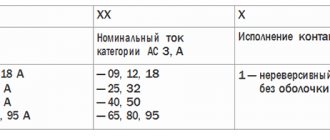
Sector designations
The operating principle of the device can be understood from the information from the sectors:
- the first indicates areas of application and general data - alternating frequency, current rating and conditional thermal current;
- from the second sector you can find out the maximum load power when connecting power contacts;
- in the third sector there is a graphic circuit with an electric magnet coil and contacts.
Magnetic starter contact groups
The following markings are used to designate power contacts:
- 1L1, 3L2, 5L3 – input elements designed to supply power from a direct or alternating current line;
- 2T1, 4T2, 6T3 – output contacts for connecting to the load;
- 13NO–14NO – auxiliary elements for self-retaining, help when the engine is running without constantly holding the Start button.
The load or power source can be connected to any of the groups.
Stop key
Start and Stop keys
Regardless of the modification, the starter for the electric motor is controlled using the “Stop” or “Start” button. Some models have a reverse mode. The stop button can be identified by its red color.
To ensure unhindered current flow, the normally closed contacts are mechanically connected to the stopper. Without pressing a key, the contacts are closed by a metal strip. To stop the device, you need to press the button - it will open. If there is no locking after lowering the button, the contacts will close.
For this reason, the electric motor is controlled using special circuits. To simplify installation, the device is mounted on a DIN rail.