Main characteristics of thermal relays
The main characteristics of a thermal relay taken into account when choosing the appropriate option:
- Rated protection current
. Selected according to the rated load current. The rated current of the thermal relay must be one and a half times higher than In of the protected motor. - Interval for adjusting
the operating current setting. - The circuit voltage and the nature of the current
are constant or alternating. If the voltage goes beyond the permissible limits, the thermal relay will fail. - Nomenclature and number of auxiliary control contacts
. Some TRs have additional contacts that control the operation of the thermal relay itself and the load being served. - Switching power
. An important property of TP, which characterizes the output power of the load. - Operation limit (threshold)
. This is a coefficient whose value depends on the value of Inom. Most often, this coefficient is in the range of 1.1-1.5. - Sensitivity to phase asymmetry
. This parameter is equal to the ratio of the skewed phase to the phase through which Inom passes. - Trip class
. Characterizes the average period of operation of the device.
What is important to know?
To avoid repetition and to avoid piling up unnecessary text, I will briefly outline the meaning. The current relay is a mandatory attribute of the electric drive control system. This device responds to the current that passes through it to the engine. It does not protect the electric motor from short circuits, but only protects against operation with increased current that occurs during overload or abnormal operation of the mechanism (for example, wedge, jamming, rubbing and other unforeseen moments).
When choosing a thermal relay, they are guided by the passport data of the electric motor, which can be taken from the plate on its body, as in the photo below:
As can be seen on the tag, the rated current of the electric motor is 13.6 / 7.8 Amperes, for voltages of 220 and 380 Volts. According to the operating rules, the thermal relay must be selected 10-20% more than the nominal parameter. The correct choice of this criterion determines the ability of the heater to operate on time and prevent damage to the electric drive. When calculating the installation current for the 7.8 A rating given on the label, we got a result of 9.4 Amperes for the current setting of the device.
When choosing a product in the catalog, you need to take into account that this value was not the extreme value on the setpoint adjustment scale, so it is advisable to select a value closer to the center of the adjustable parameters. For example, as on the RTI-1314 relay:
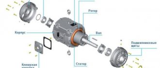
Design and principle of operation of thermal relays
To protect electric motors and other electrical equipment, TRs with bimetallic plates are most often used.
The design of a bimetallic thermal relay includes:
- Bimetallic plate
. It is made of two alloys with different coefficients of thermal expansion. Typically these are invar (low Kr) and chromium-nickel steel (higher Kr). They are welded or joined together by rolling. One of these metals heats up faster, the other slower. During current overload, part of the plate with high Kp bends towards the second part of the plate, which has lower Kp. This movement affects the group of contacts through the pusher. - Installation current regulator
. With its help, the maximum current value is set, above which the TR de-energizes the circuit. The actuation current is adjusted by increasing or decreasing the gap between the main plate and the pusher. - Electrical contacts
. They are connected to the windings of the magnetic starter of the thermal relay. Typically, a TP has two contacts - normally closed and normally open. When a bimetallic strip is subjected to force, the contacts change their position to the opposite.
The bimetallic strip is heated in one of two ways: directly due to the overload current or indirectly, through a separate heat-sensitive element. Both of these principles can be combined in one device, which significantly increases its efficiency. If the critical values of the consumer current are exceeded, the relay will open the circuit and de-energize the MP, and, consequently, the protected electrical equipment.
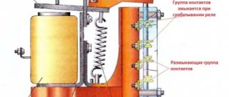
The operation of the relay element may be affected by increased ambient temperature. To compensate for this phenomenon and prevent false alarms, the TR design includes additional bimetallic plates that bend in the direction opposite to the spatial position of the main element.
Control circuit for 220 V.
One wise man said: there are 44 schemes for connecting buttons to a magnetic starter, of which 3 work, and the rest do not.
But there is only one correct one. Let's talk about it (see diagram above). It is better to leave connecting the power circuits for later. This will make it easier to access the coil screws, which are always covered by the main circuit wires. To power the control circuits, we use one of the phase contacts, from which we send a conductor to one of the terminals of the “Stop” button. This can be either a conductor or a cable core. Two wires will go from the stop button: one to the “Start” button, the second to the block contact of the starter. To do this, a jumper is placed between the buttons, and a cable core to the starter is added to one of them at the point where it is connected. There are also two wires from the second terminal of the “Start” button: one to the second terminal of the block contact, the second to terminal “A1” of the control coil. When connecting buttons with a cable, the jumper is already placed on the starter, and the third core is connected to it. The second output from the coil (A2) is connected to the zero terminal. In principle, there is no difference in what order you connect the outputs of the buttons and the block contact. It is advisable to connect only the “A2” terminal of the control coil to the neutral conductor. Any electrician expects that zero potential will only be there. Now you can connect the wires or cables of the power circuit, not forgetting that next to one of them at the input there is a wire to the control circuit. And only from this side is power supplied to the starter (traditionally - from above). Trying to connect buttons to the starter output will lead to nothing.
Types of thermal relays
Manufacturers offer several types of TRs, which differ in design features and the type of MP used.
- TRP
. Single-pole switching device with a combined heating option. Used in DC networks in which the voltage does not exceed 400 V, to protect asynchronous motors. Resistant to shock and vibration loads. - RTL
. Protects electric motors from delayed starting, current asymmetry, overloads, and phase failure. - PTT
. Provides protection for asynchronous three-phase machines with short-circuit rotor from overloads, delayed start and phase imbalance. - TRN
. Used in DC power networks. Serve to control the start-up of electrical installations and the operating mode of the engine. - RTI
. Functions in conjunction with circuit breakers or fuses. - RTK
. Designed for use in automation circuits, it controls the temperature regime in the housing of electrical equipment.
The listed TPs do not protect electrical circuits from short circuits.
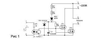
Thermal relay connection diagram
Connection of TP to power units is carried out in accordance with the manufacturer's instructions. In most cases, the TP is connected to the protected device through a normally closed contact, which is connected in series with the “stop” key. An open contact turns on thermal protection when the current exceeds the permissible values. Schemes for connecting a thermal relay to a motor circuit or other electrical equipment may be different, depending on the presence of additional devices.
Standard connection diagram for a thermal relay
The thermal relay is installed and connected together with a magnetic starter, which performs the functions of turning on the electric drive. There are options when the thermal relay is installed on a DIN rail or a separate panel.
When connecting a consumer to a 220 V or 380 V network, all phases after the magnetic starter are passed through a thermal relay, and then connected to the electric motor. When the start button is turned on, the power supply voltage enters the winding of the MP, which turns on the electric motor. If the load current increases to a value exceeding a critical value, the thermal relay is activated and turns off the electric motor.
The thermal relay TRN has only two incoming connections. In this case, the unconnected phase wire is run directly from the starter to the motor. Since the current in the electric motor varies proportionally, only two of them (any) can be controlled.
Magnetic switch
Now about what you should pay attention to when examining the starter itself before connecting it. The most important thing is the voltage of the control coil, which is indicated either on it itself or nearby. If the inscription reads 220 V AC (or there is an AC icon next to 220), then a phase and a zero are required for the control circuit to operate.
Watch an interesting video about the operation of a magnetic starter below:
If it is 380 V AC (the same alternating current), then the starter will be controlled by two phases. In the process of describing the operation of the control circuit, it will become clear what the difference is.
With any other voltage values, the presence of a direct current sign or the letters DC, it will not be possible to connect the product to the network. It is intended for other circuits.
We will also need to use an additional contact of the starter, called a block contact. For most devices, it is marked with the numbers 13NO (13NO, simply 13) and 14NO (14NO, 14).
The letters NO mean “normally open”, that is, it closes only when the starter is pulled in, which can be checked with a multimeter if desired. There are starters that have normally closed additional contacts; they are not suitable for the control circuit under consideration.
Power contacts are designed to connect the load, which they control.
Their markings vary from manufacturer to manufacturer, but there are no difficulties in identifying them. So, we attach the starter to the surface or DIN rail in the place of its permanent location, lay the power and control cables, and begin the connection.
Adjusting the thermal relay
To effectively perform the function of shutting down an electric motor or other serviced device, it is necessary to correctly adjust the TP settings so that the likelihood of false alarms is eliminated. It is recommended to carry out the adjustment on a specialized stand using fictitious loads:
- Current is passed through the temperature sensing element to simulate a real thermal load.
- Using a timer, the response time is determined. When adjusting using a control screw at a current of 1.5 In, the response time should be no more than 2.5 minutes, 5-6 In - no more than 10 seconds.
Starter control buttons
In general, you will need two buttons: one to turn it on and one to turn it off. Please note that they use contacts with different purposes to control the starter. For the “Stop” button they are normally closed, that is, if the button is not pressed, the group of contacts is closed, and opens when the button is activated. The Start button is the opposite.
These devices can either contain only a specific element needed for operation, or be universal, including one closed and one open contact. In this case, you need to choose the right one.
Manufacturers usually provide their products with symbols that make it possible to determine the purpose of a particular contact group. The stop button is usually painted red. The launcher color is traditionally black, but green is welcome, which corresponds to the “On” or “Turn on” signal. Such buttons are mainly used on cabinet doors and machine control panels.
For remote control, push-button stations are used, containing two buttons in one housing. The station is connected to the starter installation location using a control cable. It must have at least three cores, the cross-section of which may be small.
The simplest working circuit of a starter with a thermal relay
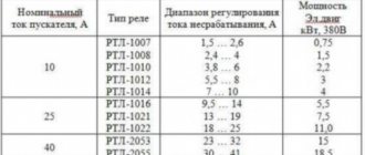
Marking of thermal relays
The labeling indicates most of the important characteristics of the TR. Example designation: RTL-Х1Х2Х3-Х4-Х5А-Х6А-Х7Х8, where
- RTL – type of thermal relay;
- X1 – rated current, 1 – up to 25 A, 2 – up to 100 A, 3 – up to 250 A, 4 – up to 510 A;
- X2 – 3 digits (conventionally), indicating the range of the current setting;
- X3 – letter characterizing the performance;
- X4 – return method: 1 – manual, 2 – self-return;
- X5 – Inom, A;
- X6 – current setting range, A;
- X7 – climatic version;
- X8 is a trademark.
A thermal relay is an effective element of protection for electric motors and other electrical equipment, which compares favorably with the input circuit breaker in that it is not subject to false alarms during short-term current surges.
Checking the functionality of the circuit.
In order to understand whether the circuit is assembled correctly or not, it is better not to connect the load to the starter, leaving its lower power terminals free. This way you will protect your switched equipment from unnecessary problems. We turn on the circuit breaker that supplies the test object. It goes without saying that it must be turned off while editing is in progress. And also, in any available way, accidental activation by unauthorized persons is prevented. If after feeding the starter does not turn on on its own, that’s good. Press the “Start” button, the starter should turn on. If not, check the closed position of the “Stop” button contacts and the state of the thermal relay. When diagnosing a malfunction, a single-pole voltage indicator helps, which can easily check the passage of a phase through the “Stop” button to the “Start” button. If, when you release the “Start” button, the starter does not lock and falls away, the block contacts are incorrectly connected. Check - they should be connected parallel to this button. A correctly connected starter should be locked in the on position when mechanically pressing on the moving part of the magnetic circuit. Now we check the operation of the thermal relay. Turn on the starter and carefully disconnect any wiring from the relay contacts. The starter should fall off.