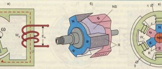
There are several classes of electrical converters, among which the so-called inductive analogues have found practical application. In them, energy conversion occurs due to the conversion of induction windings, which are an integral part of the unit itself. The windings are located on two elements - the stator and the rotor. So, what is the difference between a stator and a rotor (what are they and what are their functions?).
The simplest definition of the two parts of the converter is their functionality. Everything is simple here: the stator (of an electric motor or generator) is a stationary part, the rotor is a movable part. In most cases, the latter is located inside the former, and there is a small gap between them. There are so-called units with an external rotor, which is a rotating ring with a stationary stator inside.
Principles of stator rewinding
The electromagnetic field of the stator is created using three-phase rewinding. A certain number of coils connected to each other are attached to the grooves of the electric motor.
Options for rewinding the stationary part of electric motors depend on the type of insulation, the choice of which is determined by the following parameters:
- maximum voltage indicator;
- permissible rewind temperature value;
- dimensions and type of groove;
- type of winding.
Depending on the method of placing the coils in the stator slots, the motor is rewinded in one or two layers. Copper cable is used as the winding material.
Induction
Previously, we established how an ordinary magnet rotates in a stator. AC motors have rotors rather than magnets. Our model is very similar to a real rotor, except that the rotor is polarized under the influence of a magnetic field. This is caused by magnetic induction, due to which an electric current is induced in the rotor conductors.
Induction
Basically the rotor works the same way as a magnet. When the electric motor is turned on, current flows through the stator winding and creates an electromagnetic field that rotates in a direction perpendicular to the rotor windings. Thus, a current is induced in the rotor windings, which then creates an electromagnetic field around the rotor and rotor polarization.
In the previous section, to make it easier to explain the principle of operation of the rotor, replacing it with a magnet for clarity. Now let's replace the stator with a magnet. Induction is a phenomenon that occurs when a conductor moves in a magnetic field. The relative movement of a conductor in a magnetic field leads to the appearance of a so-called induced electric current in the conductor. This induced current creates a magnetic field around each rotor conductor winding. Since three-phase AC power causes the stator's magnetic field to rotate, the induced magnetic field of the rotor will follow this rotation. This way the motor shaft will rotate. AC motors are often called AC induction motors, or AC induction motors.
Carrying out repairs
Any electrical equipment, over time, is characterized by failures in its operation. The causes of breakdowns can range from simple pollution to exposure to external factors.
In case of malfunction, start repairing the electric motor by cleaning or purging the stator elements. Then, after removing dirt and dust, proceed to removing the product body to replace the winding. On a lathe or using a chisel, the front part of the stator rewind is cut off.
To soften the insulating material, the stator should be accelerated to a temperature of about 200 degrees, after which the winding is removed, the coil is removed and the grooves are cleaned. After disassembling the electric motor, a new stator winding is installed using ready-made templates.
After installing the coil, it is varnished, followed by drying at a temperature of 150 degrees Celsius for at least two hours.
Checking the electric motor for resistance between the housing and the winding is carried out after all parts of the stator have dried. Adjustment of the equipment to the required parameters is possible by selecting a cable for rewinding.
Stator protection using thermal relay
The essence of such protection is the use of a relay with a bimetal plate. The metal strip, under the influence of electric current, begins to bend. Upon reaching a certain temperature, the plate, under the action of a spring, disengages with a special latch and disconnects the entire electrical circuit.
The plate returns to its original position by manually pressing a button. The design of stator thermal insulation varies depending on the area of application, current ratings and relay design.
Currently, relays are produced both as part of assembly units and as independent parts. Depending on the purpose, they differ in manual and automatic operating principles. For devices designed for a narrow range of current consumption, the choice of protection requires a more responsible approach. When the electric motor is turned on, the metal strip is heated by passing a charge along a wound spiral wire.
Stator thermal insulation
During operation, cases of overheating of parts and components due to engine malfunctions cannot be excluded. An increase in the temperature of the stator winding is associated with a change in the value of the current consumed. This failure occurs due to the opening of the electrical circuit, due to the loss of the electrical signal of one of the phase wires.
Another reason for temperature changes may be mechanical wear of bearings. In this case, the insulation of the motor winding suffers, rendering it inoperative.
These days, overheat protection is used on almost all electrical appliances. It works in the following cases:
- in case of failures during starting or deceleration of the stator;
- under heavy overloads;
- during sudden power surges;
- when phase wires fail;
- when the engine is running with a jammed rotor;
- in case of drive device failures.
Car electrical equipment
All electrical equipment of any car is represented by the following components:
- Current sources:
- accumulator battery;
- generator.
- basic;
- long-term;
- short-term.
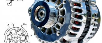
The task of the battery is to provide consumers with current while the engine is “resting”, during its startup or operation at low speeds. While the generator is, in fact, the main supplier of electricity. It not only powers all consumers, but also charges the battery.
Its capacity, combined with the power of the generator, must meet the needs of all consumers, regardless of the engine operating mode. In other words, energy balance must be constantly maintained. This is important to know, as it will allow you to understand how the generator stator works.
The main consumers usually include the fuel system, including injection, ignition, control, and automatic transmission. Some cars have electric power steering. That is, everything that constantly uses current, from starting the engine to stopping it completely.
Long-term consumers are systems that are not used very often. And this is lighting, security (passive, active), heating and air conditioning devices. Most cars are equipped with anti-theft systems, multimedia equipment and navigation.
As for short-term consumers, these are the cigarette lighter, starting system, glow plugs, signal, as well as comfort systems.
Restoring winding markings
More precisely, marking the windings is needed only to determine the direction of winding of the winding coils. The end and beginning of the winding are designated for this purpose only. The fact is that when the winding is turned on, eddy currents begin to appear in it, which move in the direction “from beginning to end”. If the windings are connected according to the principle “beginning with beginning, end with end,” then the currents will be summed up, the windings will turn into one large resistor and a huge total current will arise. The engine will start to make a loud noise and will not turn over. The windings will start to heat up very quickly and the motor will burn out. Moreover, it is quite possible that a real flame of orange-blue color will break out with a very harmful and unpleasant odor.
There is a way to determine the ends and beginnings of windings.
This whole process is shown very well in the video. The author of this video used a mains voltage of 220 Volts to test, which I highly do not recommend doing. Use step-down transformers or an autotransformer.
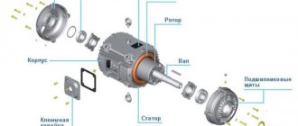
Structure of an asynchronous motor
In order to understand the theory of engine operation, we need to consider what it consists of.
- Terminal box cover.
- Terminal box.
- Housing coupling bolts.
- Rotor shaft.
- Front housing cover.
- Housing base plate.
- Housing with cooling fins.
- Manufacturer's information plate (“nameplate”).
- Case back cover.
- Additional engine cooling fan (“spinner”). The “spinner” is not installed on all engines. If the intended work location provides good air cooling, then additional airflow is not required.
In fact, an asynchronous motor consists of three parts (from left to right): rotor, stator and housing, but the main parts are considered to be the rotor and stator , which we will talk about.
What does an electric motor stator consist of?
The stator consists of two main parts - the base and the core. The base is a cast or welded body made using cast iron or aluminum alloys.
The core is made in the form of a shaft made of special steel with a thickness of 0.35 to 0.5 mm, which has undergone additional firing. It has special grooves for attaching an electric motor rewind, consisting of core wires twisted together in a parallel manner. This connection allows you to weaken eddy currents.