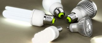
The design of an energy-saving lamp depends on the specific type of light source. In most cases, compact fluorescent lamps (CFLs) equipped with a threaded base and characterized by a power of 7 W and above are called energy-saving.
Their popularity compared to linear products is due to their compactness, the presence of a standard base (E27 or E14 for night lamps) and the absence of the need for ballasts (ballasts).
Types of energy saving lamps
There are several criteria by which energy-saving lamps are classified. The most common of them are base and glow temperature.
A socket is an element used to fix the product in a lighting fixture and supply electricity. Its main types are threaded and pin.
Most often in the domestic sphere, threaded sockets are used, screwed into ordinary cartridges. They are designated by the letter E and a numerical value indicating the diameter in millimeters. E27 is considered standard, while E14 is used in table lamps or sconces. And yet, threaded sockets are more often installed in DRL and sodium lamps intended for street lighting.
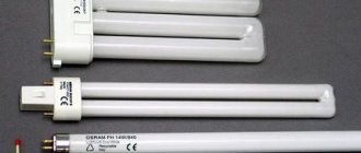
The pin type is used for specific luminaires. They are available with two or four pins, and the connectors themselves are marked with the letter G and a numerical value. Relevant for powerful lighting devices.
Depending on the glow temperature, an energy-saving lamp emits light of a certain shade (measured in Kelvin):
- Warm light (yellow) - 2700 K. The shade is similar to the glow of conventional (incandescent) lamps.
- Natural white light - 4200 K. Fluorescent lamps, neutral shade.
- Cold light (white) - 6400 K. Close to the blue spectrum, therefore it is characterized by a bluish tint. Typically used in industrial facilities in lamps of 65 W and above.
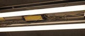
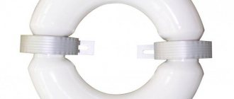
Energy-saving lamps also come in different shapes - tubular, spiral, arc-shaped. In the first case, there are no protective elements.
Conclusion
Having indicated all the main aspects of operation and the internal structure of an energy-saving lamp, we will summarize - these devices are much more practical and economical than their predecessors, incandescent lamps. They are more reliable and financially profitable. Therefore, despite their rather high price, we advise you to purchase these lighting devices, since they will pay for themselves a hundredfold over the time of use.
We hope that this article has given you an idea of what the circuit and structure of an energy-saving lamp is. Be careful when choosing how to save energy in your home.
Operating principle and design of an energy-saving lamp
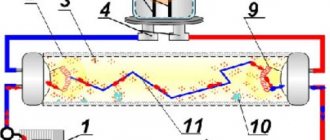
A CFL consists of a hollow glass bulb, the inside of which is filled with mercury vapor. When electric current is applied, an arc discharge is formed between the electrodes, connected to the starting capacitor. Due to this, ultraviolet radiation is formed, the spectrum of which is invisible to the human eye. To convert the glow into visible light, the inner walls are coated with a phosphor, guaranteeing a bright glow. If compared with an incandescent lamp of the same energy consumption, the luminous efficiency will be significantly higher. The cost of the device depends on what the phosphor consists of.
The disadvantage of energy-saving lamps is the fact that they cannot be directly connected to a 220 V power supply. The mercury vapor in them when turned off has a high resistance, so a pulse with a high voltage is needed to form a discharge. After the discharge is formed, the resistance becomes negative. If there are no protective elements in the circuit, this will lead to a short circuit. In tubular devices, an electromagnetic ballast is used, installed directly in the lamp.
Main performance characteristics
When choosing energy-saving fluorescent lamps, the following set of characteristics has a great influence on the scope of their further application:
- Power. Varies from 7 to 100 W and above. For domestic conditions, models up to 20 watts are sufficient (which is comparable in brightness to an incandescent lamp 5 times stronger!).
- Base modification. Selected based on the characteristics of the lamp.
- Flask geometry. It is taken into account according to the parameters of the lighting device and compliance with external conditions of use.
- Radiation temperature. Depends on the purpose of the illuminated objects.
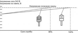
- Lifetime. Varies from 5 to 12 thousand hours.
Components of the circuit
In addition to standard structural elements, such as a bulb and a base, an electronic circuit (electronic ballast - ballast) is hidden under the housing. Not every “housekeeper” has it (for example, it is absent in CFLs). Today, ballasts remain the most reliable product for the operation of fluorescent lamps, the quality of which determines their service life.
The electronic circuit consists of the following components:
- starting capacitor - generates a powerful impulse necessary to start the lamp;
- filters - needed to eliminate radio frequency interference and electromagnetic radiation that enter the circuit along with the current (reduce flicker);
- capacitive filter - an additional element that smoothes out the remaining ripples;
- current limiting choke - to protect the circuit from high current (maintains the current at a given level);
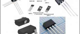
- bipolar transistors;
- driver - to limit current;
- fuse - prevents the lamp from failing, prevents the circuit from igniting during voltage surges.
Introduction.
Compact Fluorescent Lamps (CFLs) are now widely used. To reduce the size of the ballast choke, they use a high-frequency voltage converter circuit, which can significantly reduce the size of the choke.
If the electronic ballast fails, it can be easily repaired. But when the bulb itself fails, the light bulb is usually thrown away.
However, the electronic ballast of such a light bulb is an almost ready-made switching power supply unit (PSU). The only way the electronic ballast circuit differs from a real pulse power supply is the absence of an isolation transformer and a rectifier, if necessary. https://site/
At the same time, modern radio amateurs experience great difficulty in finding power transformers to power their homemade products. Even if a transformer is found, its rewinding requires the use of a large amount of copper wire, and the weight and dimensions of products assembled on the basis of power transformers are not encouraging. But in the vast majority of cases, the power transformer can be replaced with a switching power supply. If you use ballast from faulty CFLs for these purposes, the savings will amount to a significant amount, especially if we are talking about transformers of 100 watts or more.
How does ignition occur?
The voltage falling across the dinistor leads to the formation of a pulse that enters the transistor and leads to the opening of the element. As soon as the start is completed, the circuit is blocked by the diode bridge. At the moment the transistor opens, the capacitor is charged, which prevents the dinistor from opening again.
The transistor acts on a transformer made of a ferrite ring with three windings in several rows. Voltage is applied to the filaments through a resonant circuit and a capacitor.
As soon as a glow appears in the tube, it is characterized by a resonant frequency determined by a capacitive capacitor. When igniting, the voltage reaches 600 V (at the moment of starting, the value is 4–5 times higher than the average), so it is necessary to monitor the integrity and tightness of the bulb. If this is ignored, the transistors will be damaged.
When the gas in the flask is completely ionized, the capacitor with the largest capacity is bypassed. The frequency decreases, control passes to the second capacitor. The voltage is reduced to a value sufficient to maintain the lamp glow. The cathode and anode are swapped, which ensures uninterrupted operation of the electronic circuit and simplifies repairs if necessary.
Disassembly and diagnostics
To get to the device microcircuit, you just need to open the housing cover. The body is divided into two parts, which are fastened together with latches and can be easily removed if necessary. We recommend disassembling an already unusable lamp, since when disassembling a working one, there is a chance of rendering it unusable. At first glance, the lamp is solid and impossible to disassemble, but this is not the case. If you carefully examine the case, you will see a special groove, which, by prying it with a knife or screwdriver, you can easily open the case, but this must be done without sudden movements.
Once you have separated both parts from each other, you will notice that they are connected to each other by a pair of wires. They also need to be carefully disconnected from the microcircuit, which can be done with a soldering iron by unsoldering the required ends from the board. Sometimes, on some lamps, the ends of the wires are wound around the contacts, so you can simply unscrew them. You now have two separate light bulb parts on your hands.
The electronic board is usually round and either yellow or green in color. This electrical circuit is the main control device of an energy-saving lamp. If the lamp burns out, then on the board you can see swollen and leaking capacitors, as well as burnt contacts. Four wires go to the board from the bulb, which are wound around the contacts. Usually they are located at the ends of the board in the opposite direction from each other. Different light bulbs use either a fuse or a resistor, which prevents the light bulb from burning out, but the light itself burns. Next you can see the inductor and capacitor. They regulate the blinking frequency of the lamp. The circuit itself is designed to regulate and control the ignition of the lamp, its incandescent temperature, and also prevent voltage surges.
That's all you need to know about the design of your home energy-saving lamp.
How repairs are made
To find the cause of the malfunction, you should disassemble the lamp into its component parts. Detach the top and bottom parts and turn off the flask. Using an ohmmeter, check the filament coils on the bulb itself. If one of them burns out, repair the bulb. To complete the helix, use a 10 ohm high power resistor. In addition, remove the diode that shunts this spiral (if there is one in the circuit).
If a resistor burns out in lamps with a power exceeding 30 W (inclusive), there is a high probability of transistor failure, which is associated with a breakdown of the capacitor. To correct the situation, a new resistor is installed to act as a fuse, and the transistors are also replaced.
Modernization is also possible. Drill the holes necessary for ventilation in the base. Some models of energy-saving lamps are already produced with them, but there are unscrupulous manufacturers who do not think about cooling.
Important! Never use lamps with a drilled base in rooms with high humidity levels. This can lead to failure of the capacitor or the entire device.
We identify faulty elements on the ballast board.
Fuse.
First of all, we check the fuse. It's easy to find. One end of it is soldered to the central contact of the lamp base, and the other to the board. A tube made of insulating material is put on it. Typically, fuses do not survive such a malfunction.
But as it turned out, this is not a fuse, but a half-watt resistor with a resistance of about 10 ohms
, and was burnt out (in a cliff).
The serviceability of the resistor is easily determined. Place the multimeter in resistance measurement mode to the “ continuity
"or "
200
" and take the measurement.
If the fuse resistor is intact, then the device will show a resistance of about 10 ohms
, but if it shows
infinity
(one), then it is broken. You can read how to measure resistance here.
Here, place one multimeter probe to the central contact of the base, and the second to the place on the board where the lead of the fuse resistor is soldered.
One more thing. If the fuse resistor turns out to be burnt out, then when you bite it, try to bite it closer to the resistor body, as shown on the right side of the top picture. Then we will solder a new resistor to the terminal remaining in the base.
Bulb (lamp).
Next, check the resistance of the bulb filaments. It is advisable to unsolder one pin on each side. The resistance of the threads should be the same, and if it is different, it means one of them has burned out. Which is not very good.
In such cases, experts advise soldering a resistor parallel to the burnt spiral with the same resistance as that of the second spiral. But in my case, both spirals turned out to be intact, and their resistance was 11 Ohms
.
The next step is to check all semiconductors for serviceability - these are transistors
,
diodes
and
zener diode
. If you don’t know how to test a transistor or diode, then read the article on how to test a transistor with a multimeter.
As a rule, semiconductors do not like working with overloads and short circuits, so we check them carefully.
Diodes and zener diode.
There is no need to unsolder the diodes and zener diode; they already connect perfectly right on the board. The direct resistance of the pn junction of the diodes will be within 750 Ohms
, and the inverse must be
infinity
. All my diodes turned out to be intact, which made me a little happy.
Double-anode zener diode
, therefore, in both directions it should show a resistance equal to
infinity
(one).
If some of your diodes turn out to be faulty, then you need to purchase them at a radio components store. 1N4007 are used here
. But I couldn’t determine the value of the zener diode, but I think that you can install any one with a suitable stabilization voltage.
Transistors.
The transistors, and there are two of them, will have to be unsoldered, since their base-emitter pn junctions are shunted by the low-resistance winding of the transformer.
One transistor rang both right and left, but the second was supposedly intact, but between the collector and emitter, in one direction, showed a resistance of about 745 Ohms
. But I didn’t attach any importance to this, and considered it faulty, since this was the first time I was dealing with transistors of type 13003.
I couldn’t find transistors of this type in a TO-92 package, so I had to buy a larger one in a TO-126 package.
Resistors and capacitors.
They also need to be checked for serviceability. But what if.
I still had one SMD resistor, the value of which was not visible, especially since I did not know the circuit diagram of this ballast. But there was another similar working energy-saving lamp, and it came to my rescue. It shows that the value of resistor R6
is
1.5 Ohm
.
To finally make sure that all possible faults were found, I rang all the elements on the working board and compared their resistance on the faulty one. And he didn’t solder anything.
1. Transistors 13003 – 2 pcs. 10 rubles each (in the TO-126 case - I took 10 pieces); 2. SMD resistors - 1.5 Ohm and 510 kOhm, 1 ruble each (I took 10 pieces); 3. 10 Ohm resistor – 3 rubles per piece (I took 10 pieces); 4. Diodes 1N4007 – 5 rubles per piece (I took 10 pieces just in case); 5. Heat shrinkage – 15 rubles.
Disposal
Specific disposal is required only for luminescent products that contain mercury vapor in the bulb. LED light bulbs can be thrown into regular trash - the same place as regular and halogen bulbs.
Energy-saving lamps are a great option for people who want to save on energy bills. A huge number of advantages make CFLs preferable to conventional or halogen ones.
If you choose a specific model, it is better to overpay a little and purchase LED products that are characterized by greater durability and eliminate the negative impact on human well-being.
In conclusion
The principle of operation of energy-saving compact lamps is similar to the principle of operation of fluorescent linear lighting devices. However, the compact version has certain advantages. First of all, an electronic ballast is already built into it, the electronic ballast is equipped with high-quality parts that prevent flicker and noise during operation. Manufacturers also managed to significantly reduce the size of the lighting fixture by bending it into a spiral or arc.
Housekeepers have high efficiency and allow you to consume less electricity, but be careful with their use, there is mercury inside the gas discharge tube, so these products require special disposal.
Read more
- Acceptance of energy-saving lamps by the population
- Ripple coefficient of energy-saving lamps
- Dimmer for energy saving lamps
The difference between a CFL circuit and a pulse power supply.
This is one of the most common electrical circuits for energy-saving lamps. To convert a CFL circuit into a switching power supply, it is enough to install just one jumper between points A - A'
and add a pulse transformer with a rectifier. Elements that can be deleted are marked in red.
And this is a complete circuit of a switching power supply, assembled on the basis of a CFL using an additional pulse transformer.
To simplify, the fluorescent lamp and several parts were removed and replaced with a jumper.
As you can see, the CFL circuit does not require major changes. Additional elements introduced into the scheme are marked in red.
Differences between the lamp design and the pulse unit
The circuit of an energy-saving lamp is very similar in structure to a switching power supply, which is why making a switching power supply can be done very easily and quickly. To remake, you need to install a jumper and additionally install a transformer that generates pulses and is equipped with a rectifier.
To make the UPS lighter, the glass fluorescent lamp and some structural components were removed and replaced with a special connector. You may have noticed that to make a change you only need to perform a few simple operations, and this will be quite enough.
Board with energy saving lamp
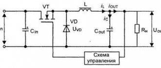
The output power indicator is limited by the size of the transformer used, the maximum possible throughput of the main transistors and the dimensions of the cooling system. To increase the power a little, just wind more windings on the inductor.
What does ESL consist of?
The design of an energy-saving lamp is quite simple.
It consists of two main parts: a glass bulb and a body. These elements are connected to each other by special wires that are wound to four pins located in pairs at the edges of the board. On some models they may be soldered. An electronic circuit is installed in the housing; it is also called ballast. A distinctive feature of compact fluorescent lighting devices is that they already have an electronic ballast; it does not have to be connected separately.
The housing, which houses all the electronics, can be made of infusible plastic or ceramic. It ends with a base or pins, with which the light bulb can be screwed into a socket or lamp. Modern ESLs are adapted for Russian users; they have the following bases:
- E27 (standard Edison base with a diameter of 27 mm);
- E14 (reduced minion base, mainly found in chandeliers, lamps, sconces);
- E40 (large base with a diameter of 40 mm, which is most often used in industrial production).
To understand the principle of operation of an energy-saving lamp, you need to understand how each of its components works. Let us consider in more detail the internal structure of the device and the features of its elements.