The operating principle of pulse-type DC/DC converters is based on the phenomenon of self-induction. When the current flowing through the inductor is interrupted, an emf is generated in the magnetic field that is induced around it, and a voltage of reverse polarity is generated at its terminals. By controlling the current and switching time of the circuit, the self-induction voltage can be adjusted.
A DC/DC switching converter is an electronic circuit that contains an inductor. It is cyclically connected to and disconnected from the power source. Since the coil requires cyclic charging, the circuit must also include a capacitor that filters the electrical signal and maintains the output voltage. A transistor or thyristor acts as a control element that controls the time of passage of electric current.
Converters are used to build power supplies in computer technology, telecommunications equipment, automated control systems, and mobile devices. They provide a change in the output DC voltage up or down relative to the input voltage.
There are several types of DC/DC converters. The choice of model depends on what the power source is needed for and what its characteristics should be. The main operating parameters of pulse converters are:
- output voltage. It can be fixed and adjustable within a certain range;
- input voltage;
- output current. It determines how powerful a load can be powered from the source. Converter power is calculated using the formula P = U*I, where U is Voltage, and I is electric current;
- voltage stabilization;
- pulsation magnitude;
- Efficiency
Also, when choosing, you need to pay attention to the presence of protection systems against overloads, overheating and short circuits, and the presence of galvanic isolation, which eliminates the possibility of supplying dangerous input voltage to the output contacts.
According to the purpose of the device there are:
- downward;
- increasing;
- inverting.
Powering circuits using transformer power supplies
In traditional transformer power supplies, the voltage of the supply network is converted, most often reduced, to the desired value using a transformer. The reduced voltage is rectified by a diode bridge and smoothed out by a capacitor filter. If necessary, a semiconductor stabilizer is installed after the rectifier.
Transformer power supplies are usually equipped with linear stabilizers. Such stabilizers have at least two advantages: low cost and a small number of parts in the harness. But these advantages are eroded by low efficiency, since a significant part of the input voltage is used to heat the control transistor, which is completely unacceptable for powering portable electronic devices.
Output Capacitor Selection
The output capacitor is necessary to suppress the overshoot and ripple that occurs at the output of the buck converter. Insufficient capacitance of this capacitor leads to large surges, and too high equivalent series resistance (ESR) leads to large voltage ripples. The maximum permissible values for surges and ripples are usually determined during development. Therefore, in order for a buck converter circuit to meet the ripple requirements, it must include an output capacitor with sufficient capacitance and low ESR.
When the load of the converter suddenly decreases sharply, a voltage surge occurs at its output, significantly exceeding the stabilized value. To prevent the release of excess energy stored in the inductance into the load and exceeding the maximum permissible value of the output voltage, it is necessary to correctly determine the capacitance of the output capacitor. The voltage surge at the output can be calculated using formula (2).
From formula (2) we get:
where Co is the capacitance of the output capacitor and ΔV is the maximum voltage surge at the output.
If we set the maximum value of the output surge equal to 100 mV, then using formula (3) we obtain the calculated value of the output capacitor capacitance equal to 442 μF. If we add to this the typical capacitor capacitance variation of 20%, we get a practical output capacitor capacitance of about 530 µF. The closest standard rating is 560 µF. The output ripple on this capacitor can be calculated using the formula:
The ESR of the output capacitor is the main factor affecting the ripple range. Their value can be calculated as follows:
Please be aware that a capacitor with too low an ESR may cause inverter instability. The influence of this factor on stability varies from chip to chip, so when choosing a capacitor, you must carefully read the reference data and pay special attention to the section on converter stability.
The addition of the output ripple, determined by the capacitance of the output capacitor (the first term in formula (4)), and the ripple determined by the ESR (the second term in formula (4)), gives the total value of the ripple at the output of the buck converter:
Let us transform expression (4) to obtain ESR (5).
A quality buck converter will typically produce an output ripple of less than 2% (40 mV in our case). According to formula (5), for an output capacitor with a capacity of 560 μF, the ESR value should not exceed 18.8 mOhm. Therefore, you need to choose a capacitor with an ESR less than 18.8 mOhm and a capacitance greater than or equal to 560 µF. To obtain an ESR value less than 18.8 mOhm, several low ESR capacitors can be connected in parallel.
In Fig. Figure 3 shows the dependence of the output voltage ripple on the capacitance and ESR of the output capacitor. Since our example uses tantalum capacitors, the ESR of the capacitor dominates in determining the output ripple.
Powering Circuits Using Dc Dc Converters
If the equipment is powered from galvanic cells or batteries, then voltage conversion to the required level is possible only with the help of Dc Dc converters.
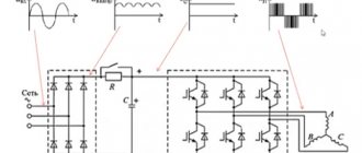
The idea is quite simple: direct voltage is converted into alternating voltage, usually with a frequency of several tens or even hundreds of kilohertz, increased (decreased), and then rectified and supplied to the load. Such converters are often called pulse converters.
An example is a boost converter from 1.5V to 5V (computer USB output voltage).
Dc Dc converter 1.5V/5V
Pulse converters are good because they have high efficiency, ranging from 60..90%. Another advantage of pulse converters is a wide range of input voltages: the input voltage can be lower than the output voltage or much higher.
Properties of inverters [edit | edit code ]
- Voltage inverters make it possible to eliminate or at least weaken the dependence of the operation of information systems on the quality of alternating current networks. For example, in personal computers, in the event of a sudden network failure, with the help of a backup battery and an inverter, forming an uninterruptible power supply
(UPS), it is possible to ensure that the computers operate to correctly complete the tasks being solved. In more complex critical systems, inverter devices can operate in a long-term controlled mode in parallel with the network or independently of it. - In addition to “independent” applications, where the inverter acts as a power source for AC consumers, energy conversion technologies have become widely developed, where the inverter is an intermediate link in the chain of converters. The fundamental feature of voltage inverters for such applications is the high conversion frequency (tens to hundreds of kilohertz). Effective energy conversion at high frequencies requires a more advanced element base (semiconductor switches, magnetic materials, specialized controllers).
- Like any other power device, the inverter must have high efficiency, high reliability and acceptable weight and size characteristics. In addition, it must have an acceptable level of higher harmonic components in the output voltage curve (acceptable value of harmonic coefficients) and not create during operation a level of ripple at the terminals of the energy source that is unacceptable for other consumers.
- In pure metering systemsGr > Inverter operation
The operation of a voltage inverter is based on switching a constant voltage source to periodically change the polarity of the voltage at the load terminals. The switching frequency is set by control signals generated by the control circuit (controller). The controller can also solve additional tasks:
- voltage regulation;
- synchronization of key switching frequency;
- protecting them from overloads, etc.
According to the principle of operation, inverters are divided into:
- voltage inverters (VIN), example - inverters of most UPSs;
- current inverters (AIT), example - Soviet airfield converter APChS-63U1;
- resonant inverters (AIR);
dependent (inverters driven by the network), an example is the power converter of electric locomotives VL85, EP1, etc.
Classification of Dc Dc converters
In general, Dc Dc converters can be divided into several groups.
Step-down, in English terminology step-down or buck
The output voltage of these converters is, as a rule, lower than the input voltage: without any significant heating losses of the control transistor, you can get a voltage of only a few volts with an input voltage of 12...50 V. The output current of such converters depends on the load demand, which in turn determines the circuit design of the converter.
Another English name for a step-down converter is chopper. One of the possible translations of this word is interrupter. In technical literature, a step-down converter is sometimes called a “chopper”. For now, let's just remember this term.
Increasing, in English terminology step-up or boost
The output voltage of these converters is higher than the input voltage. For example, with an input voltage of 5 V, the output voltage can be up to 30 V, and its smooth regulation and stabilization is possible. Quite often, boost converters are called boosters.
Universal Dc Dc converter – SEPIC
The output voltage of these converters is maintained at a given level when the input voltage is either higher or lower than the input voltage. Recommended in cases where the input voltage can vary within significant limits. For example, in a car, the battery voltage can vary within 9...14 V, but you need to get a stable voltage of 12 V.
Inverting Dc Dc converter - inverting converter
The main function of these converters is to produce an output voltage of reverse polarity relative to the power source. It is very convenient in cases where bipolar power is required, for example to power op-amps (operational amplifiers).
All of the mentioned converters can be stabilized or unstabilized; the output voltage can be galvanically connected to the input voltage or have galvanic voltage isolation. It all depends on the specific device in which the converter will be used.
To move on to a further story about Dc Dc converters, you should at least understand the theory in general terms.
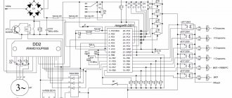
Control method
Frequency converters are controlled in different ways. The main commands include: start, stop, speed control, emergency braking. These actions can be performed both from the inverter panel and from the remote control. This concerns the issuance of commands from the operator to the equipment. The FM can control the operation of the electric drive of motors in the following ways:
Scalar regulation is based on a constant ratio of output voltage and frequency (Uout/Fout). This method does not require the use of a sensor indicating the current position of the rotor. It is used where the loads do not change and there are no increased dynamic loads.
Important! With this adjustment, the load on the engine affects the speed: with a large load the speed decreases, with a small load it increases. The vector method relies not only on control over U/F, but also the angle and magnitude of the space vector (phase)
With this method there is no inertia of adjustment; it is carried out in a wide range of speeds
The vector method relies not only on control over U/F, but also the angle and magnitude of the space vector (phase). With this method there is no inertia of adjustment; it is carried out in a wide range of speeds.
Attention! With the vector method, the load does not affect the rotation speed; constant speed is achieved by automatically adjusting the output voltage
Buck Dc Buck Converter
Its functional diagram is shown in the figure below. The arrows on the wires show the directions of the currents.
Functional diagram of chopper stabilizer
The input voltage U in is supplied to the input filter - capacitor C in. The VT transistor is used as a key element; it carries out high-frequency current switching. This can be a MOSFET, IGBT structure transistor, or a regular bipolar transistor. In addition to the indicated parts, the circuit contains a discharge diode VD and an output filter - LC out, from which the voltage is supplied to the load R n.
It is easy to see that the load is connected in series with elements VT and L. Therefore, the circuit is sequential.
How does voltage drop occur?
Pulse width modulation - PWM
The control circuit produces rectangular pulses with a constant frequency or constant period, which is essentially the same thing. These pulses are shown in the figure below.
Control pulses
Here t is the pulse time, the transistor is open, tp is the pause time, the transistor is closed. The ratio ti/T is called the duty cycle duty cycle, denoted by the letter D and expressed in %% or simply in numbers. For example, with D equal to 50%, it turns out that D=0.5.
Thus, D can vary from 0 to 1. With a value of D=1, the key transistor is in a state of full conduction, and with D=0 in a cutoff state, simply put, it is closed. It is not difficult to guess that at D=50% the output voltage will be equal to half the input.
It is quite obvious that the output voltage is regulated by changing the width of the control pulse t, essentially changing the coefficient D. This regulation principle is called PWM pulse width modulation (PWM). In almost all switching power supplies, it is with the help of PWM that the output voltage is stabilized.
In general, converters have become so widely used that manufacturers of electronic components have started producing PWM controllers for all occasions. The assortment is so large that just to list them you would need a whole book. Therefore, it never occurs to anyone to assemble converters using discrete elements, or as they often say in “loose” form.
Moreover, ready-made low-power converters can be purchased on Aliexpress or Ebay for a low price. In this case, for installation in an amateur design, it is enough to solder the input and output wires to the board and set the required output voltage.
Now let's return to our buck-type step-down converter, the complete circuit is shown above.
In this case, coefficient D determines how long the key transistor will be open (phase 1) or closed (phase 2). For these two phases, the circuit can be represented in two drawings. The figures DO NOT SHOW those elements that are not used in this phase.
Phase 1
When the transistor is open, the current from the power source (galvanic cell, battery, rectifier) passes through the inductive choke L, the load Rн, and the charging capacitor Cout. At the same time, current flows through the load, capacitor Cout and inductor L accumulate energy. The current iL GRADUALLY INCREASES, due to the influence of the inductance of the inductor. This phase is called pumping.
After the load voltage reaches the set value (determined by the control device settings), the VT transistor closes and the device moves to the second phase - the discharge phase. The closed transistor in the figure is not shown at all, as if it does not exist. But this only means that the transistor is closed.
Phase 2
When the VT transistor is closed, there is no replenishment of energy in the inductor, since the power source is turned off. Inductance L tends to prevent changes in the magnitude and direction of the current (self-induction) flowing through the inductor winding.
Therefore, the current cannot stop instantly and is closed through the “diode-load” circuit. Because of this, the VD diode is called a discharge diode. As a rule, this is a high-speed Schottky diode. After the control period, phase 2, the circuit switches to phase 1, and the process repeats again. The maximum voltage at the output of the considered circuit can be equal to the input, and nothing more. To obtain an output voltage greater than the input, boost converters are used.
It should be noted that in fact, not everything is as simple as written above: it is assumed that all components are ideal, i.e. switching on and off occurs without delay, and the active resistance is zero. In the practical production of such circuits, many nuances must be taken into account, since a lot depends on the quality of the components used and the stray capacitance of the installation. Just about such a simple part as a throttle (well, just a coil of wire!) More than one article could be written.
For now, we just need to remind you about the amount of inductance, which determines the two operating modes of the chopper. If the inductance is insufficient, the converter will operate in the breaking current mode, which is completely unacceptable for power supplies.
If the inductance is large enough, then operation occurs in the continuous current mode, which makes it possible, using output filters, to obtain a constant voltage with an acceptable level of ripple. Boost converters, which will be discussed below, also operate in the continuous current mode.
To slightly increase the efficiency, the discharge diode VD is replaced with a MOSFET transistor, which is opened at the right moment by the control circuit. Such converters are called synchronous. Their use is justified if the power of the converter is large enough.
How to make an AC/AC converter
AC/AC and DC/DC converters have identical circuits. Only in AC/AC converters it is necessary to exclude polar elements and use power switches that “... are capable of being either in a closed (conducting) or open (non-conducting) state and allowing current to flow or block the flow in any direction.” If the first condition is intuitive - you cannot use polar elements on alternating current, then the second condition needs to be explained in more detail.
Today, mechanical contacts (for example, relay contacts), semiconductor diodes, bipolar transistors, MOSFETs and IGBTs can be used as power switches from the available element base (Figure 1).
| Picture 1. | Current flow in power elements. |
Diodes, bipolar transistors and IGBTs pass current in only one direction, and the diode is an uncontrolled element. Therefore, these devices cannot be used as independent switches for AC/AC converters. The conductive channel of a MOSFET allows current to flow in both directions, and its resistance is determined by the voltage between the gate and source. In theory, a MOSFET is quite suitable for converting alternating current. However, the presence of a parasitic diode in these devices means that the current cannot be blocked for one of the directions. Thus, the only elements that can be used for the AC/AC converter keys are mechanical contacts. They can either pass current or block its flow in any direction. But mechanical contacts physically cannot switch at high frequencies, have low reliability, high noise levels and many other disadvantages, which is why they are not used in modern converters.
As a result, none of the devices shown in Figure 1 can be used as a full-fledged independent power switch of an AC/AC converter, therefore, in AC voltage converters, the power switches are a combination of several semiconductor devices (Figure 2). Similar circuits are used in matrix converters and are described in detail in.
| Figure 2. | Power switches for AC/AC converters. |
It is immediately clear that these circuits have a serious drawback - current flows through at least two power elements: a diode and a transistor, which negatively affects the efficiency and cost of the converter. But perhaps more effective solutions will appear in the future. For example, RB-IGBT and BD-IGBT are mentioned, but these devices, in terms of their characteristics, availability and cost, have not yet reached a level sufficient for widespread use.
| Figure 3. | Buck (a), boost (b) and inverting (c) AC/AC converters. |
Of the above solutions, the circuit in Figure 2c is of greatest interest, since in it one driver can control two transistors, for which, due to lower control losses, it is better to use MOSFET or IGBT. When using a MOSFET, if the voltage drop across the open channel is less than the forward voltage across the diode, current will flow only through the transistor channels, and the diode will not take part in the conversion process. For IGBT-based switches, you can use devices with a built-in antiparallel diode. This allows you to reduce the number of packages and simplify the board layout, although this reduces the cooling of the crystals
When choosing an IGBT with a built-in diode, you must also pay attention to the thermal resistance of the junction-body of the diode - it should be commensurate with the same resistance of the transistor, because in some devices the diode can have several times greater thermal resistance than the transistor
To build an AC/AC converter, you can take any DC/DC converter circuit, exclude polar elements, and use controlled bidirectional power switches shown in Figure 2 as traditional transistors and diodes. As an example, Figure 3 shows the circuits of classic (basic) AC /AC converters of buck, boost and inverting types. When converting alternating current, they will perform the same functions: lower, raise and invert the input voltage.
Boost Dc Dc converter – boost type converter
Boost converters are used mainly for low-voltage power supply, for example, from two or three batteries, and some design components require a voltage of 12...15 V with low current consumption. Quite often, a boost converter is briefly and clearly called the word “booster”.
Functional diagram of a boost converter
The input voltage U in is applied to the input filter C in and supplied to the inductor L and the switching transistor VT connected in series. A VD diode is connected to the connection point between the coil and the drain of the transistor. The load R n and the shunt capacitor C out are connected to the other terminal of the diode.
The VT transistor is controlled by a control circuit that produces a control signal of a stable frequency with an adjustable duty cycle D, just as was described just above when describing the chopper circuit. The VD diode blocks the load from the key transistor at the right times.
When the key transistor is open, the right output of the coil L according to the diagram is connected to the negative pole of the power source U in. An increasing current (due to the influence of inductance) from the power source flows through the coil and the open transistor, and energy accumulates in the coil.
At this time, the diode VD blocks the load and output capacitor from the switching circuit, thereby preventing the output capacitor from discharging through the open transistor. The load at this moment is powered by the energy accumulated in the capacitor C out. Naturally, the voltage across the output capacitor drops.
As soon as the output voltage drops slightly below the set value (determined by the settings of the control circuit), the key transistor VT closes, and the energy stored in the inductor, through the diode VD, recharges the capacitor C out, which energizes the load. In this case, the self-induction emf of the coil L is added to the input voltage and transferred to the load, therefore, the output voltage is greater than the input voltage.
When the output voltage reaches the set stabilization level, the control circuit opens the transistor VT, and the process repeats from the energy storage phase.
Inverter Converter Design
Let's look at typical boost converter circuits and look at the design and calculation process in detail. At the end of the article there will be a form in which you can fill in the necessary source parameters, carry out the calculation online and get the denominations of all elements. This form calculates denominations for all three schemes at once. If the circuit you have chosen does not contain these elements, then their values should be ignored.
Scheme 1
Scheme 2
Scheme 3
The boost topology is the simplest to implement, since the emitter (source) of the power transistor is not connected to the common wire. There is no need for special tricks when applying control voltage to the base (gate). It is enough to apply this voltage directly. There are also no problems with generating a feedback signal. If the load current is relatively small, then it is quite easy to remove the current limit signal. A resistor is installed in the emitter (source) circuit. If the current through this resistor exceeds the maximum permissible, then the voltage across this resistor exceeds the controller protection response voltage, and the key is forced to close.
If the load current is large, then energy losses on resistor R7 become an unacceptable luxury. Then a current transformer is used.
If a low-power controller is used that is not capable of driving a powerful bipolar transistor, then you need to install an additional transistor, as shown in the diagram. The use of a composite transistor is undesirable, since the energy loss on the transistor is greater, the higher the collector-emitter saturation voltage, and the saturation voltage of a composite transistor is several times higher than that of a conventional one.
Diagram 3 shows the use of a current transformer and an additional low-power transistor. But this does not mean that they can only be used together. The current transformer can be used in circuits with a field-effect transistor and in circuits with a powerful controller. A low-power transistor can be used in circuits with resistor R7. These two solutions are shown in the same diagram just for example
Note! If in circuit 3 a PWM controller with an open emitter at the output is used to control transistors, then a resistor with a resistance of 300 - 400 Ohms must be connected between the base and emitter of the VT7 transistor to reliably block the VT7 transistor. If the controller output has a push-pull cascade, as in the microcircuit that we use, then there is no need for such a resistor
What to do if the input voltage is greater than the permissible gate voltage of the field-effect transistor or the permissible supply voltage of the controller is described in the article about a step-down converter. For the raiser, the solution is completely similar.
For example, we use the 1156EU3 microcircuit as a PWM controller.
The circuits use a powerful bipolar transistor or a powerful field-effect transistor as a power switch. Read more about the operation of a bipolar transistor and a field-effect transistor as a power switch.
(read more...) :: (to the beginning of the article)
:: SearchSafety :: Help
Unfortunately, errors are periodically found in articles; they are corrected, articles are supplemented, developed, and new ones are prepared. Subscribe to the news to stay informed.
If something is unclear, be sure to ask!Ask a question. Discussion of the article.
Inverting pulse voltage converter, power supply.... How does an inverting voltage stabilizer work? Where is it used? Description…
Charger. Pulse car charger. Charging the battery... Scheme of a pulse charger. Calculation for different voltages and currents….
Switching power supply. With my own hands. Homemade. Do. Labo... Scheme of a switching power supply. Calculation for different voltages and currents….
Bridge pulse stabilized voltage converter, source... How a bridge voltage stabilizer works. Where is it used? Description of the…
Power powerful pulse transformer, choke. Winding. Make... Techniques for winding a pulse inductor / transformer....
Step-down pulse voltage converter, power supply. Co... How to design a buck switching converter. Step 1. How to choose a cha...
LED power supply. Driver. LED flashlight, flashlight. With your own hands... Turning on the LEDs in the LED flashlight....
Do-it-yourself uninterruptible power supply. Do it yourself UPS, UPS. Sine, sinusoid... How to make an uninterruptible power supply yourself? Pure sinusoidal output voltage, with...
Universal Dc Dc converter – SEPIC
SEPIC (single-ended primary-inductor converter) or a converter with an asymmetrically loaded primary inductor.
Such converters are mainly used when the load has insignificant power, and the input voltage changes relative to the output voltage up or down.
Functional diagram of the SEPIC converter
Very similar to the boost converter circuit shown in the previous figure, but has additional elements: capacitor C1 and coil L2. It is these elements that ensure the operation of the converter in the voltage reduction mode.
SEPIC converters are used in applications where the input voltage varies widely. An example is 4V-35V to 1.23V-32V Boost Buck Voltage Step Up/Down Converter Regulator. It is under this name that a converter is sold in Chinese stores, the diagram of which is shown in the figure below.
Schematic diagram of SEPIC converter
Below is the appearance of the board with the designation of the main elements.
Appearance of the SEPIC converter
You should pay attention to the presence of two coils L1 L2. Based on this feature, you can determine that this is a SEPIC converter.
The input voltage of the board can be within 4…35 V. In this case, the output voltage can be adjusted within 1.23…32 V. The operating frequency of the converter is 500 KHz. With small dimensions of 50 x 25 x 12 mm, the board provides power up to 25 W. Maximum output current up to 3 A.
But a remark should be made here. If the output voltage is set at 10 V, then the output current cannot be higher than 2.5 A (25 W). With an output voltage of 5 V and a maximum current of 3 A, the power will be only 15 W. The main thing here is not to overdo it: either not to exceed the maximum permissible power, or not to go beyond the permissible current limits.
We will be glad if you subscribe to our Blog!
[wysija_form id=”1"]
Recuperation mode
And what happens if the average value of the magnetic flux of the FSR choke has a sign opposite to ΔФ, for example, if FNACHKON START KON? In this case, according to (7), WIMP
| Figure 9. | Recovery mode. |
When is such a regime necessary? For example, if the converter input is connected to the system power bus, and the output is connected to a battery containing an emergency energy reserve (Figure 10). In normal mode, the system is powered by the main source, and the converter acts as a charger, with energy transferred from the input to the output of the converter, which corresponds to the transfer mode. If the battery is charged, then the energy is not transferred anywhere, and the converter operates in idle mode. In the event of a failure of the main source, energy from the battery through a converter operating in recuperation mode is supplied to the power bus, providing power to the load.
| Figure 10. | An example of the converter operating in three modes. |
It should be noted that the transition from one mode to another occurs automatically, without any participation from the controller, whose main task in this case is only to maintain the required ratio t1/t2 so that, according to (9), provide or the required value of UВХ /UOUT, or required load current.