What is a stand-alone inverter
In power supply technology, an inverter is a device that provides a transition from direct voltage to alternating voltage.
As one of the functional modules, it is included in the list of required solar battery units and allows you to obtain standard single-phase or three-phase network voltage from direct current.
Depending on the design features, the applied switching circuit and the list of tasks to be solved, the inverter can have different designs, which is reflected in schematic form in the classification of the figure.
Figure 1. Hierarchy of inverters
The device can be considered as an uninterruptible power supply with expanded functionality.
At the same time, it differs from conventional entry-level UPS primarily in the following main features:
- contains several equal inputs for connecting various sources of electrical energy to them;
- independently controls sources of electricity, providing voltage and frequency of the power network regulated by standards throughout the entire range of permitted loads;
- provides complete isolation of the external electrical input from the intra-house network, for which the functions of the source of electrical energy, regardless of the operating mode, are always taken over by the inverter.
The latter feature determined the generally accepted designation of this device as an autonomous inverter.
Electricity DC and AC
When science teachers explain the basic idea of electricity as the flow of electrons, they usually talk about direct current (DC). We learn that electrons are a bit like a line of ants, walking along with packets of electrical energy in the same way that ants carry leaves. This is a pretty good analogy for something like a basic flashlight, where we have a circuit (a solid electrical loop) connecting a battery, a lamp, and a switch, and electrical energy is systematically transported from the battery to the lamp until all the battery's energy is depleted.
In larger appliances, electricity works differently. The power source, which comes from a wall outlet, is based on alternating current (AC), where the electricity switches between 50 and 60 times per second (in other words, at a frequency of 50 and 60 Hz). It's hard to understand how AC delivers energy when it's constantly changing its mind about where it's going. If the electrons coming out of the wall socket travel, say, a few millimeters down the cable, then they need to reverse the direction and go back, just like how do they ever get to the lamp on the table to make it light up?
The answer is actually quite simple. Imagine that the space between the lamp and the wall is filled with electrons. When you flip the switch , all the electrons filling the cable vibrate back and forth in the lamp filaments - and this rapid shuffling converts electrical energy into heat and lights the lamp. Electrons do not necessarily have to rotate in a circle to transfer energy: in AS they simply “run in place.”
Where is it used and how is it turned on?
In relation to solar energy, an autonomous inverter, as a device that primarily performs the functions of selecting one of the possible sources of power supply, is installed between the output of the solar battery and the input panel.
The installation location is dictated by simple considerations: the electricity consumer should not know from which source he receives electricity at a given specific point in time, and the required quality of this energy, incl. at the moment of switching between sources, is determined by the choice of appropriate circuit solutions and the element base used.
For reasons of ensuring maximum operational flexibility of intra-house wiring, the external input connection can also be physically made to the house input panel, which is separately highlighted in Figure 2.
Figure 2. Scheme of interaction between the external network, autonomous inverter, input panel and consumers in normal operation
At the same time, this input is equipped with all the necessary accessories and circuit breakers for protection against short circuits, excessively high leakage currents and the like.
The strength of this approach is that it allows, if necessary, without problems, by simply reconnecting just a few terminals, to switch to a standard power supply circuit in which there are no alternative sources.
Methods of application
Current converters from 12 to 220 V are especially widely used in places where there is no electricity supply. Any car battery can be used to supply 220 V to supply electricity to a country house.
It should be remembered that voltage inverters from 12 V to 220 V convert a form of electrical current that limits its use. That is, not all electrical devices are able to perceive voltage supplied graphically in an almost rectangular shape. Structurally, inverters are:
- automobile;
- stationary;
- mobile.
If we consider the output power, then car batteries produce a maximum of 500 W, and stationary ones - up to 10 thousand W. If, when leaving the city on vacation or at a summer cottage, it is necessary to illuminate a room or overnight stay in the evening, then the easiest way is to connect an LED lamp to the converter.
Stationary voltage converters 12-220 volts are mainly used to transform electrical energy from solar panels and wind structures. Mobile inverter converters are connected to a network from 12 to 50 V and are considered unpretentious in choosing a power source. For car maintenance, this device is a charger with a socket.
Device
From a functional point of view, an autonomous inverter is an uninterruptible power supply, supplemented by a multi-input power switch, an output voltage driver and equipped with a control unit.
The operating algorithm of the control unit in some cases can vary within fairly wide limits.
The block diagram of this device, which indicates the individual blocks and shows the features of their interaction, is presented in Figure 3.
Figure 3. Simplified block diagram of an autonomous inverter
It is believed that matching of the type of current (DC - AC) and voltage values of a specific input and general output is carried out in the switch circuit.
External input, solar and battery batteries, as well as a gas generator in this case are considered as mutually complementary energy sources and cannot operate in parallel.
The order of their connection to the output of the input panel for subsequent power supply of power consumers can be strictly specified, taking into account the priorities set by the equipment designer.
Older inverter models have the ability to independently determine this sequence by the user or project developer through appropriate programming.
This allows you to fully take into account the local characteristics of the electrical equipment implemented at a specific residential property.
With appropriate programming in the mode of receiving energy from an external input or a gas generator, it is also possible to charge the battery to a full or other selectable capacity.
Transformerless voltage converters
Recently, they have become very popular, since their production, and in particular the production of transformers, requires a lot of money, because their winding is made of non-ferrous metal, the price of which is constantly growing. The main advantage of such converters is, of course, the price. Among the negative aspects, there is one thing that significantly distinguishes it from transformer power supplies and converters. As a result of a breakdown of one or more semiconductor devices, all the output energy can reach the terminals of the consumer, and this will certainly damage it. Here is the simplest AC to DC voltage converter. The role of the regulating element is played by the thyristor.
The situation is simpler with converters that do not have transformers, but operate on the basis and in the mode of a voltage-increasing device. Here, even if one or several elements fail, dangerous destructive energy will not appear on the load.
Difference from grid and hybrid inverter
Potentially, all the described functions can also be performed by the so-called. a hybrid inverter, which from this angle can be considered as the most technically advanced representative of the type of technology under consideration.
Its main difference is the ability to return excess generated electricity back to the network.
The practical use of hybrid inverters is hampered primarily not by technical problems in the implementation of this technology, but by the lack of an appropriate legal framework.
Current regulatory documents do not provide for the very possibility of independent generation of electricity by a private individual and its sale to an energy sales company.
A direct consequence of this state of affairs is also the lack of serial certified bidirectional meters as equipment that is necessary to perform mutual settlements after the end of the reporting period (for example, a calendar month that is familiar to everyone).
Taking into account the hierarchy presented in Figure 1, a network inverter is considered against the background of a hybrid device of a lower class, which implements the following simple two-mode operating algorithm:
- during the day, if there is sufficient power supplied by the solar battery, the intra-house network is disconnected from the electrical input and is fully provided with electrical energy from an alternative source;
- in the morning, evening and at night, as well as in cloudy weather, when the solar battery is not able to ensure the normal functioning of household consumers, the inverter is turned off and, due to the bypass switch, the household is supplied entirely from the electricity supply company's network.
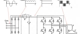
Types by method of current switching
The 220 or 380 V output voltage driver, separately highlighted in the diagram in Figure 3, which is necessarily present in any inverter, is implemented only using a pulse circuit.
The benefit of such a solution is determined by the fact that when the key semiconductor element is in a completely open and completely closed state, due to the minimum voltage or, accordingly, the minimum current, a significant reduction in the power of useless energy losses is achieved.
All this allows you to increase the overall efficiency of the device to values over 90%, Figure 4.
Figure 4. Instantaneous and average efficiency of a switching type inverter
In fact, the main losses occur at the moment of transition from one state to another, which determines the presence of additional high requirements for the key elements of the device and their performance.
The peculiarity of pulse circuits is that, unlike analogue ones, the output voltage is not pure, but so-called. approximated sinusoid.
Operating principle of a resonant type inverter generator
The resonant circuit for constructing an autonomous inverter generator is inferior in popularity to the push-pull one, incl. due to the difficulty of ensuring normal functioning at idle.
From a circuit design point of view, it differs favorably from its push-pull analogue by the possibility of implementation on only one active element (due to the rather low efficiency, it becomes ineffective at powers above 200 - 300 W).
The idea of a resonant circuit is that an alternating voltage is created by an oscillating circuit, i.e. with the correct selection of parameters and, first of all, the choice of denominations L and C, its shape will be close to sinusoidal.
A single key element or a combination of them is designed to input energy from a direct current source into this circuit, which allows you to compensate for internal losses and create the corresponding work in the load.
Depending on the type of connection of the oscillatory circuit and the load, such generators are divided into serial, parallel and partially parallel.
Additionally, a distinction is made between closed and open type circuits, the only difference between which is whether direct current flows through the inductance.
If it is present, they speak of closed circuits, and if it is absent, they speak of open resonant generators.
One of the possible circuits of the simplest resonant inverters is shown in Figure 6.
Figure 6. Simplified circuit diagram of an autonomous resonant inverter generator
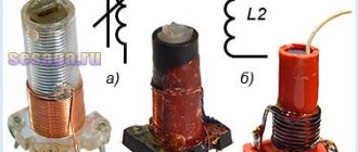
Inverter design
Initially, the creation of alternating voltage in the circuit was ensured by literally switching wires from one terminal to another. This is how mechanical inverters worked, which are sometimes used today. These are rather bulky devices with low efficiency.
With the development of semiconductor technology, it became possible to change poles without the use of mechanical devices. For this purpose, thyristors are used, semiconductor devices that act as electronic keys. It is also possible to use another element base - transistors in combination with diodes. Thyristors are switched by control signals generated automatically. In the simplest case, their source can be an ordinary relay operating at strictly defined intervals. Modern inverters use software to create control pulses. This makes it possible to vary the frequency and amplitude of the alternating current.
An important part of the inverter is the converter. It increases the voltage to the required value, most often from 12 volts at the battery output to 220 at the input to the thyristor bridge. Converters are often also sold as separate devices.
The use of capacitors and freewheeling diodes in circuits of autonomous resonant inverters
A certain increase in conversion efficiency is achieved by introducing various additional elements into the resonant inverter circuit. Most often, capacitors and so-called are used. freewheeling diodes.
Capacitor C1 in Figure 6 is connected in parallel with the load if it has significant inductance. The purpose of this element is to maximize the cosφ parameter.
The essence of the use of the so-called reverse diodes, which are switched in counter-parallel to each key element, is to create conditions for the recovery of energy accumulated in the reactive elements by returning it to a constant voltage source.
Any of the reverse diodes is locked in the open state of the key element and opens upon transition to the locked state, which allows you to “reset” the energy of the reactive elements L and C back to the “I” source.
Criteria for selecting autonomous inverters
When choosing a stand-alone inverter, pay attention to several main characteristics. Let us highlight the main parameters and their features.
Number of phases
When choosing the number of phases, consider the following points:
- If your home is supplied with three-phase voltage (380 V), the stand-alone inverter must also be three-phase.
- In a situation where only single-phase voltage (220 V) is connected to the machine, the equipment must be appropriate.
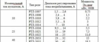
Nominal/peak output power
It is optimal that the rated power of an autonomous inverter is equal to the sum of the loads (consumers in the house). For reliability, it is better to buy equipment with a reserve and taking into account inrush currents.
Starting factor I is typical for refrigeration equipment, pumps and other equipment with an induction load. In it, currents at the moment of startup can be 7-10 times higher than the rated parameter.
To calculate, multiply the starting current by the voltage in the house and compare with the peak power parameter (the first indicator should be lower).
If the developer has not indicated the peak power parameter of the autonomous inverter, this means that the nominal parameter is in reality peak.
Form U out
This is a key parameter on which the quality of receivers depends.
There are three types here:
- Pure sine.
- Quasi sine wave.
- Rectangular sine wave.
To avoid operational problems and equipment damage, it is recommended to choose a stand-alone inverter with the correct sine wave.
This is because inductive loads are very sensitive to the voltage waveform. If the output of the device is a square sine wave, the main equipment will not work and may break down.
A quasi sine wave is a compromise between a pure and a rectangular sine wave. Most of the models of autonomous inverters on the market that have this characteristic are of high quality. But you need to be careful, because there are also unreliable options.
Equipment protection
A good model of an autonomous inverter should have a full range of various types of protective characteristics.
Let us highlight the main types of protection:
- from overheating;
- battery protection;
- from short circuit;
- from overload at the output.
If the model has a fan for forced temperature reduction, check with your consultant whether it functions in all situations or only turns on when the load increases above a certain value.
In the best models, the fan turns off at minimum load. As a result, the autonomous inverter produces less noise, which is important when installing it in a residential building.
Efficiency
Using the efficiency parameter, you can understand how much energy the device spends without benefit. The best representatives have an efficiency ranging from 90 to 95%. If this parameter is less than 90%, 1/10 of the energy will be wasted, which is unacceptable for solar stations.
Own consumption
The indicator displays how much power the equipment consumes without a load connected to it. It is optimal if this parameter is no more than 1% of the rated power.
For example, if the Snom of an autonomous inverter (rated power) is 3000 W, its own consumption should not exceed 30 W. If the device will be constantly connected to the network, it is better to choose a model with a low power setting.
Availability of sleep/standby mode
The essence of the option is to turn off the device if it is not used for a long time and there is no load.
In this case, the own power drops to three to six watts. At the same time, the autonomous inverter is in constant current monitoring mode in order to turn on at full power at any time.
But there is a peculiarity. To avoid difficulties with powering devices with light loads, you need the option to manually disable standby/sleep mode. In this case, the owner will be able to activate and deactivate the function himself if necessary.
If shutdown is not provided, it is possible that the autonomous inverter will remain in standby mode when a low-power load is connected, for example, charging.
In conclusion, we note that do not buy too cheap devices, because their quality may be far from ideal. It is better to choose models taking into account the manufacturer, characteristics and other parameters.
What is an inverter, also known as a voltage converter from 12 to 220 Volts?
Simple converter circuits, principles of operation, types of inverters according to output voltage forms.An inverter (in the narrow electrical engineering sense of the word) is a device for converting direct current into alternating current with a change in the effective voltage value. In an even narrower sense - a converter of direct voltage (12, 24 or 48 V) into alternating voltage 220 V. And finally, in a radically narrow sense - a contraption that allows you to power various household appliances designed for mains power from a car battery, and in short - a very useful and an easy-to-use gadget!
Based on the form of output voltage, inverters are divided into the following types:
- Direct rectified voltage 220 V or alternating pulse voltage of high frequency (tens of kilohertz). Such converters are used extremely rarely, because they are unsuitable for many sources of consumption; moreover, for some they can pose a serious danger and the threat of complete failure.
- Square wave 50 Hz. They are also rarely used, since the output voltage contains a large number of high-frequency components. Suitable for powering telephone chargers, most switching power supplies, incandescent lamps, fluorescent and LED lamps. Unsuitable for devices with iron-based power transformers and AC electric motors.
- Modified sinusoidal voltage 50Hz. Almost everything works from inverters with a modified sine wave, but less efficiently than with a pure sine wave. Some appliances may run hotter, buzz more, and operate at reduced power. Undesirable for working with electric motors and compressors, as well as sensitive radio equipment with 50 Hz transformers.
- Pure sinusoidal voltage. Suitable without any restrictions for any electricity consumers!
From the above it follows that inverters with an output voltage of 220 V and a frequency of 50 Hz are preferable and more universal.
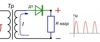
Moreover, ready-made low-frequency power transformers of the required rated power, switched on “back to front,” are suitable for their implementation. That is, its secondary low-voltage winding serves as the primary, and the high-voltage primary winding serves as the secondary. It is precisely these schemes that we will consider in this article. The circuit shown in Fig. 1, as well as comments to it, are borrowed from the book by M. A. Shustov “Practical Circuit Design”, section - “Voltage Converters”. Fig. 1 Circuit of a simple voltage converter 220 V, 50 Hz
“The maximum output power of the converter is 100 W, efficiency is up to 50%. The master oscillator is made according to the circuit of a traditional symmetrical multivibrator, made on transistors VT1 and VT2 (KT815). The output stages of the converter are assembled using composite transistors VT3 and VT4 (KT825). These transistors are installed without insulating gaskets on a common radiator. The device consumes a current of up to 20 A from the battery. A ready-made 100 W network transformer is used as a power transformer (the cross section of the central part of the iron core is about 10 cm2). It should have two secondary windings, each rated at 8V/10A. In order for the operating frequency of the master oscillator to be equal to 50 Hz, the values of resistors R1 and R2 are selected.” Since the multivibrator generates a meander with blocked fronts, and powerful emitter followers repeat this shape, an alternating current will flow in the load, resembling a sinusoid in shape and no additional smoothing measures are required.
The efficiency of the inverter can be significantly increased if transistors operating in switching mode are used as power stages rather than voltage repeaters. This modification of the converter is shown in Fig. 2.
Fig. 2 Diagram of a simple voltage converter with increased efficiency
The principle of operation of the converter is the same as that of the previous device. The master generator (T1, T2) generates two para-phase voltages with a frequency of 50 Hz. Voltages from the outputs of the master oscillator are supplied to two key stages of the same type (T3, T4), which switch the voltage on the primary winding of the transformer. Since the multivibrator generates a square wave with blocked edges, the key transistors operate with some delay, causing the formation of a kind of modified sinusoidal voltage at the inverter output. With the elements indicated in the diagram, the output power of the converter is about 200 W. Further increases in efficiency and inverter power can be achieved by simply replacing bipolar key elements with high-power MOSFET transistors, as shown in Fig. 2.
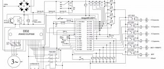
Numerous and quite popular inverter circuits, built on specialized microcircuits for switching power supplies (such as TL494, TL594, etc.) have the following advantages: high efficiency and no less high frequency stability, little dependent on the supply voltage and external conditions. Let us give as an example a similar circuit of a pulse voltage converter +12V to ~220V with a power of 100W, published in the magazine “Radioconstructor” - 07 - 17.
Fig.3 Schematic diagram of a pulse voltage converter +12V to ~220V
“The equivalent generation frequency is 50 Hz and is set by the resistance value of resistor R5 and the capacitance of capacitor C5. Resistor R4 regulates the duty cycle of the output pulses. They can regulate the output voltage. At the outputs of the microcircuit (pins 9 and 10), antiphase pulses are released, slightly delayed relative to each other, so as not to cause a through current in the output stage circuit at switching moments. The pulses are supplied to powerful key field-effect transistors VT1 and VT2. Diodes VD2 and VD3 protect these transistors from emissions of negative EMF on the primary winding of pulse transformer T1.
Transformer T1 is a ready-made low-frequency power transformer with a rated power of 100W with one primary winding at 220V and a secondary winding at 18V with a tap from the middle. You can also try a transformer with a secondary winding of 12V with a center tap or 24V with a center tap. But in the second case, I’m afraid that the output voltage will be slightly lower than 220V. The transformer is turned on “back to front”, that is, its secondary low-voltage winding now serves as the primary, and the high-voltage primary winding serves as the secondary. Having connected the load and the multimeter, use resistor R4 to set the voltage on the load to 220V.”
Many circuits built on TL494, TL594, etc., for all their advantages, often have one significant drawback. If you do not take care of correctly setting the “dead time” of the IC (in the above diagram, with resistor R4), then the voltage at the output of the converters will have a shape close to the shape of a meander with all the ensuing consequences. Moreover, no additional chokes, as well as capacitors in the secondary winding of the transformer, will lead to a significant result!
But dear comrade A.P. Semyan in his book “500 Circuits for Radio Amateurs” pleased us with an original circuit design with the formation of a modified sine wave using a 561IE8 digital microcircuit (Fig. 4).
Fig. 4 Diagram of a simple pulse voltage converter on the 561IE8 chip
A master oscillator with a frequency of 500 Hz is assembled on elements DD1.1, DD1.2. The divider on DD2 generates two pulse sequences with a frequency of 50 Hz with phases shifted by 180° to control the power switches VT1 and VT2 of the push-pull converter. To avoid through switching currents between turning off one switch and turning on another, there is a “dead zone” equal to 10% of the period duration. When a high level (logical “1”) is applied to the “Lock” input, both output keys are locked. The output power of the converter is limited by the power of power transformer T1 and the maximum permissible current of the output transistors. Transformation coefficient of the power transformer Kt = 20.
IRFZ034 (15A), IRFZ044 and RG723A (30A), IRFZ046 (50A), IRFP064 (100A) are suitable as output transistors. For device reliability, it is recommended to have a double current reserve and a triple voltage reserve. Power circuits should be as short as possible and made with wires of the appropriate cross-section.
Creating converters with a pure 50-Hz sine wave usually involves the use of microcontroller bells and whistles, which makes consideration of this issue (for us valiant electronics engineers) not so simple and inappropriate within the framework of this article.
Popular models
To simplify the choice, we will consider several models of autonomous inverters, highlighting their nuances and parameters.
Inverter / UPS SILA EP20-300
Model SILA EP20-300 is a universal equipment that combines the options of an uninterruptible power supply, charger and converter.
It is possible to automatically switch the modes of input U from the battery or from the network. Ensures continuous operation of connected equipment.
The inverter is used as a UPS (if there is a battery) or in conjunction with a solar power plant (an external charge controller is required). Country of origin: Taiwan.
Main parameters:
- Protection against short circuit, high and low voltage.
- Fast switching - 6 ms.
- Autostart after protection operation.
- LCD display.
- Automatic charging (3-step): constant current/voltage, charge support.
- Pure sine output.
Characteristics:
- Large U range at the output - from 140 to 280 V.
- Current adjustment - from 5 to 10 A (set by program).
- Stabilization of U at the output.
- Nominal / maximum power - 300 / 900 W.
- Battery voltage is 12 V.
- Efficiency - 90%.
- Personal consumption - 24 W.
- Warranty - 2 years.
Model SILA EP20-300 is capable of operating at humidity levels from 0 to 90% and over a wide temperature range. The dimensions of the autonomous inverter are only 31.5x14.5x21 cm, and the weight is 7.5 kg. Similar models with power of 600 and 1000 W are available for sale.