What are measuring instruments made of?
The measuring instruments consist of a primary measuring element and a transducer. A primary element is a device that converts a physical quantity into an electrical or non-electrical output signal. For example, thermocouples have an electrical output signal. For example, diaphragms, thermometers, and pressure gauges have a non-electrical output signal. Thermocouples produce a signal in millivolts. Diaphragms produce a signal in the form of a pressure difference before and after the diaphragm. But both of these elements are called primary converters. The non-electrical signal is then converted back into an electrical signal. For further signal processing and transmission over a distance.
The primary transducer can be a thermocouple, a diaphragm, Bourdon tubes, various emitters with receivers of ultrasonic, optical, electromagnetic, and radiation signals. The primary element can be a metal plate that changes the oscillation frequency depending on the fluid flow rate. For an example, you can see the photo.
Flow meter emitter. The receiver looks similar
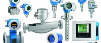
Flow meter, pressure and temperature sensors
Rotameter, pressure gauge, thermometer, dew point analyzer
Many different devices have been invented over many years of the existence of such a science as Control and Measuring Instruments (CIS). For each physical quantity, different types of transformations are used. All these transformations are based on knowledge of elementary physics. For example, the stronger the water flows in a pipe, the faster the turbine blades installed in the pipe will rotate. Another example is when two identical metal plates, when “glued” together, will bend. Because when heated or cooled, one will change its length more, the other less. We only need to convert these non-electrical parameters into any signal that we could see, in units of measurement that we understand. There are a lot of ways to do this. Each device manufacturer has its own developments for this. The generally accepted signals of primary elements are primary temperature transducers , these are thermocouples and thermal resistances. They will be described in more detail on a separate page. Basically, device manufacturers use their own designs and the signal from the primary converter is unknown to us.
Manufacturers can also use several different types of conversion in one measurement tool. For example, crude oil moisture meters. The primary converter uses both the capacitive measuring principle and the optical measuring principle.
Certificate data of the BOESN moisture meter indicating the calibration values of the capacitive channel and optical channel.
Other manufacturers produce measuring instruments with double conversion of environmental parameters into a primary signal. For example, Rosemount 3051 flow meters.
Rosemount 3051 Flowmeter
There is only one measuring device, and the conversion of the flow velocity of the measured medium into the pressure difference before and after the measuring element is used. This pressure difference is then converted into an electrical signal.
The secondary device converts the signal from the primary transducer into a standard electrical signal . In many cases, each measuring instrument that has a primary element has only its own secondary element. When working with such measuring instruments, it is always necessary to check the compliance of the primary and secondary elements with the passport for the measuring instruments. The secondary converter can also be in the form of a device combined with the controller. The controller can receive various signals from primary measuring elements, process their signals programmatically, and perform calculations of one parameter. For example, the amount of heat consumed.
Secondary devices of the thermal metering unit
Primary elements during their production may have slight deviations. These deviations are compensated for when setting up the secondary converter.
When working with devices that have a primary measuring element and a secondary transducer, it is imperative to read the safety precautions when working with the device. Many manufacturers do not allow the primary converter to be turned off without removing the voltage from the secondary unit. The device may malfunction .
General information
A lot depends on the functioning of control and measuring instruments and automatic equipment in production, including the timely release of goods, labor safety and the absence of emergency situations. Many people are interested in: what is an instrumentation mechanic? This is an employee who monitors the serviceability of such equipment at the enterprise.
Due to technological progress and constant changes in equipment, this employee is required to constantly develop and improve his skills. Sometimes he is required to be inventive and rationalize the use of technology. The positive qualities of this specialization are a constant income, the significance of the work for society, as well as the great demand for such specialists. Disadvantages most often include the need for constant development of new technologies, the risk of emergency situations and increased responsibility.
What is instrumentation
Instrumentation and control instruments are associated with specific activities in production, which involve measuring various parameters of a product, or a technological process, or some conditions.
What can be considered common is that both spare parts and instrumentation are in demand not continuously, but periodically, therefore, places were allocated for them in a warehouse nearby, and they were issued for work according to a similar procedure.
What is instrumentation and automation
With the automation of production, a lot of new things began to arrive in instrumentation. This is especially true for automatic rather than automated production. These two words differ from each other only in that in automated, human participation is assumed, and in automatic, everything is done by machines. Car factories have entire assembly lines where everything is assembled by robots. Entire automated sections, lines, workshops began to appear at different factories... And this has not surprised us for a long time. Without such automation it is no longer possible to produce entire groups of goods. For example, integrated circuits are made completely automatically, simply because a person is already there and cannot help in any way: what is produced is visible only under a microscope.
instrumentation and automation
The role of a person is reduced to periodic measurement of some parameters. That's why we added one letter. The abbreviation KIP began to look like KIPiA. The second “and” is a conjunction. Decoding of the abbreviation: “Instrumentation and automation.”
It is clear that now the walls of those former spare parts and instrumentation warehouses have long “moved apart,” figuratively speaking. To store all the spare parts for robots and boxes with devices, no matter how diverse, just as bizarre, a rack or two is no longer enough, and Aunt Masha the storekeeper, who issues them for weekly or monthly preventive maintenance. Now, in the factories of companies producing high-tech equipment, there is an “Instrumentation and Control Automation” service everywhere, which should ensure the uninterrupted operation of all devices and all automation. Actually, this is the basis for ensuring the operation of the production itself. Because as soon as a glitch sneaks into the service, everything will come to a standstill. Some tiny part from a small device is missing, they forgot to order and buy it - that’s all. The company may face huge losses.
What is the calibration interval?
Depending on the quality of the elements used, the type of materials, tests performed and operating conditions, manufacturers guarantee the preservation of device parameters for a certain period of time. This period of time is called the “intervalidation interval”. After this time has expired, it is necessary to check (verify) whether the measuring instrument corresponds to the parameters specified in the passport. The calibration interval is usually also indicated in the passport. For one device model, there may be a different calibration interval, depending on the year of manufacture.
When checking a measuring instrument, the magnitude of the change in the SI output signal at a certain measurement point is determined. For example 0; 25; 50; 75 and 100% of the measurement scale. Measurements are made both when the range increases from 0 to 100%, and when the range decreases from 100% to 0. All measured values are compared with the passport data. Deviations of measurement values from the passport data are called the error of the measuring instrument. Each device has its own tolerance. How to correctly carry out measurements is described in the Measurement Methodology (MI) for this measuring instrument. The magnitude of the permissible error is indicated in the passport for measuring instruments and in a document called “Type Description for the measuring instrument.”
What types of instrument errors are there?
4.1. Absolute error
Absolute error is the difference in readings between the measured value and the certified value. The absolute error is determined in the units in which the instrument readings are displayed. For example, for temperature transmitters this is degrees Celsius (Kelvin). The absolute error of an instrument may vary from one instrument to another. For example, in the range of 0-300 degrees there is one value. In the range of 300-1000 degrees there is a different value. An example of calculating the absolute error. At a set temperature of 200 degrees Celsius, the device shows 201 degrees Celsius. The difference between the true value and the measured value is 1 degree. This is an absolute error.
4.2. Relative error
Relative error - measured in %. To determine the relative error, it is necessary to determine the absolute error of the device. Then divide the resulting error by the number corresponding to the specified value of the medium being measured. The resulting value is multiplied by 100. The relative error is usually calculated for flow converters. For example, in a special testing device we set the flow rate to 200 cubic meters per hour. The device readings are 201 m3/h. The absolute error will be 1 m3/h. We divide the resulting value of 1 by the flow rate we set to 200. We get the number 0.005. All that remains is to multiply this value by 100%. We get the number 0.5%. This will be the relative error.
4.3. Reduced error
The given error is measured in the same way as the relative error in percent. In this case, this is the error of the device relative to the measurement scale. To calculate the reduced error, we first also determine the absolute error. Then we multiply the resulting value by the measurement limit. And to get % we multiply by 100. The given error is usually indicated for pressure gauges. Let's look at an example. The pressure gauge input has a measuring range of 0-200 kPa, and a testing device supplies 100 kPa. The reading on the pressure gauge corresponds to 102 kPa. The absolute error will be 2 kPa. Dividing 2 kPa by 200 kPa, we get a value of 0.01. Multiplying this value by 100% we get the reduced error of 1%.
4.4. Main error.
Main error. All three of these errors relate to the main error. Determination of relative, reduced and absolute errors is carried out in laboratory conditions, under environmental conditions that meet the requirements of the verification methodology.
4.5. Other types of errors.
Other types of errors. In addition to the main error in measurements, there are many more errors. I will not describe all types of errors. I’ll just list as an example what other types they are. This is additional, systematic, random, statistical, dynamic, instrumental, etc.
A measuring instrument whose characteristics during verification do not exceed the permissible values is considered suitable for further use. For measuring instruments whose error exceeds the permissible values, the primary or secondary converter is adjusted. The setting can be done either through software (by changing the coefficients) or mechanically. For example, by rotating variable potentiometers, changing the position of jumpers, or grinding the diaphragm. Sometimes, of course, we may not even suspect that at the moment some coefficients are changing. For example, when supplying test gas to a portable gas analyzer. The gas analyzer itself changes its settings programmatically. After automatic setup, the gas analyzer gives us a signal that the setup is complete and the date of the next verification.
Types of signals used in instrumentation.
Having familiarized ourselves a little with measuring instruments, we already understand that the readings of some measuring instruments can only be seen “in situ”. Only where they are mounted. These are, for example, thermometers (mercury, alcohol, bimetallic), pressure gauges, various flow meters, etc. But some measuring instruments generate their signal and transmit it via the measurement channel to the panel device or controller. In order to avoid different types of signals from different manufacturers, it was decided to use standard measuring signals.
Output signals are:
- 5.1 Pneumatic signals
- 5.2 Electrical signals
Responsibilities of an instrumentation mechanic
In accordance with the requirements of the professional standard, an instrumentation mechanic must know the operating principle of the equipment he controls, be able to repair and maintain it. For example, to service electrical equipment, it is necessary to obtain the appropriate specialized education; general knowledge of the basics of electrical engineering will not be enough.
Depending on the specifics of the equipment being serviced, the mechanic’s workplace may have the following devices and sets of tools: an instrumentation cabinet, switchboards, equipment installed on consoles, measuring devices, sockets for connecting electrical appliances, etc.
Workplace of an instrumentation service specialist
This specialty requires that the employee understands both the equipment entrusted to him and the general technology of the process.
Work of the Kipovets service
The nature of the work of the service is for the most part different from the nature of the rest of continuous production. The economy of modern enterprises is diverse and multifaceted, and measuring instruments are available everywhere. Therefore, the instrumentation and automation service consists of divisions. Some Kipovites (Kipia-vtsy? - this abbreviation has not caught on because it doesn’t sound) are engaged in electrical measuring instruments, others are engaged in chemical analysis and devices associated with them, others are engaged in gas analyzers, pressure meters (manometers), and temperature.
Instrumentation and Control Service
The specifics of the duties also vary: some are engaged in checking instruments in metrological services, others carry out periodic measurements for preventive purposes, others are on duty at automation control panels around the clock in shifts, monitoring the norms of all equipment parameters. If these are furnaces in a boiler room, then it is necessary that the instruments correctly display temperature, pressure, and the quality of fuel combustion, and that the automation reacts normally to all deviations. Likewise in other cases. The task of such a KIP worker is to react in a timely manner to equipment failure and take action. Usually the automation itself turns on the device to replace the faulty one, then the KIPO employee must ensure that this disabled unit is replaced with a suitable one and send the damaged one for repair. The instrumentation service may also have a repair department. It receives such damaged blocks and can repair them on its own. It’s easy to change if you have your own spare parts base - a microcircuit, a resistor, a capacitor. Or send it for repair to other organizations.
Kipovtsy differ “by rank”. The lowest rank of a labor worker is an instrumentation mechanic. A mechanic can work in instrumentation of any direction and on any basis. If he works with pipes, then he is a pipeline fitter, if he works with electricity, then he is an electrician, if he works with mechanics, then he is a mechanic. And he can work in any of the departments of this service. Beginning Kipovites usually immediately become mechanics. But even a born electronics engineer can proudly wear this title all his life.
We recommend reading: Why are capacitors needed in radio electronics and what are they?
Instrumentation mechanic
For repairs and adjustments, they usually hire a full-time unit - an instrumentation and control equipment adjuster. The decoding here is simple, this is exactly the repair service inside the instrumentation itself. Specialists of a wider profile, since they can deal with everything that is found in modern complex devices: there are sensors on different physical bases, electronic circuits that require diagnostics and re-soldering, and microcontrollers that need to be reprogrammed or re-flashed. Beginners, of course, are not placed here, but in order to gain experience, an instrumentation mechanic may well help the service technician.
Instrumentation and automation engineer
Master of Instrumentation and Automation. It is clear that the master is usually involved in organizing the work of a group of Kipovites. But this is usually an experienced specialist, and training his wards and sharing his wealth of experience with them is part of his responsibilities.
Instrumentation and Control Master
Instrumentation engineer. This is the final authority in the service. A circuit analyzer who knows the latest successful circuit solutions and follows progress in his field. Of course, helping adjusters in difficult cases. It is his responsibility to select data that can help solve problems, using the entire arsenal of modern information technology.
Instrumentation engineer
Equipment
The equipment includes both the measuring instruments themselves and all the equipment that supports the measurement process. And also all the necessary material: consoles, tables, observation windows. The measurement process is provided by electricity, which means that this necessarily includes power supplies, wiring, switchboards, and automatic shutdown. Most often, the equipment is much more complex and sophisticated than the measuring instruments themselves. In addition, recording or recording equipment, as well as communication and storage equipment, are used to record readings.
Instrumentation and automation equipment
5.1. Pneumatic signals of measuring instruments with an output signal of 0.2-1.0 kg/cm2.
Modern technologies require the most accurate measurements of process parameters. The greater the accuracy of the instruments during measurements, the higher the quality of the products and the fewer losses in commercial calculations. Therefore, in the modern world, measuring instruments with a pneumatic signal are used less and less. But they are still produced and used. For example. Difference pressure transducers DMPK-100.
There is no photo, but you can see its characteristics on the manufacturer's website. Output signal 0.2-1.0 kg/cm2. This is the output pneumatic signal. The limit of the given error is 0.5-1%. These devices are large in size and heavy, and are inconvenient to maintain. But in some industries they are still used.
5.2. Electrical signals of instrumentation and automation.
Electrical signals of instrumentation and automation are divided into:
- 5.2.1. Discrete
- 5.2.2. Analog
- 5.2.3. Digital
- 5.2.4. Frequency
5.2.1 Discrete electrical signals
Discrete electrical signals can be normally closed - N.C. and normally open (normally open) - N.O. Essentially, these are various contact devices that switch contacts when the permissible parameter value is exceeded. An alarm is issued. These can be electric contact pressure gauges, pressure switches, temperature alarms, flow alarms, non-contact position indicators (magnetic contact, capacitive or inductive), etc.
But modern technologies use discrete sensors with very complex control circuits, which cannot simply be represented as a relay contact. Let's take the vibrating level switch “VEGASWING 61” as an example.
5.2.1.1. Setting the level switch.
This is a rather complex device and to properly connect it to a secondary device you need to know its operating principle. The alarm has many different types of contacts and switches. In the electrical diagrams of the design documentation, only a normally closed or normally open contact is drawn. In addition, there is an LED indicator by which we can determine whether there is liquid between the electrodes or not.
Let's look at the settings options. To do this, it is necessary to understand what state of the process medium is normal for a level switch - the presence of liquid or the absence of liquid. When installing a detector on the suction of a pump or on a tank as a low level detector, etc. The normal technological state will be the presence of liquid between the electrodes of the signaling device. In this case, according to the diagram, it must output a normally open signal to the secondary device. And the LED should light green (the generally accepted light signaling of normal operation). According to the instruction manual, it is difficult to understand how to choose the correct switch position - A or B
To select the state of the LED signal, we supply power to the level switch. We immerse the level indicator plug in water. Use the operating mode switch to set the green color of the LED signal. This may cause the output relay to switch. Using a multimeter, we determine the contact that will be open in this position. After installation in a technological apparatus or pipeline, we connect signal wires to these contacts.
Why is it necessary to set the LED color to green? For example. If the technological process is disrupted, the level gauge may go beyond the measurement limits. In this case, the level gauge readings can show both 0% and 100%. Depends on the level gauge output signal settings. It may happen that the level gauge simply fails. It can be difficult to depressurize a container and determine the presence or absence of a level. In this case, it will be possible to open the level switch and determine its status. Green LED – normal state. The LED is red – the level indicator has tripped. But for some reason it also did not send a signal to the control system.
When installing a level detector for signaling the maximum level value, move the operating mode switch to position A or B on “air”. The green LED should be lit. We use a multimeter to determine whether the contact is open. When the indicator plug is immersed in liquid, the LED should light up red. The contacts should close. You can connect signal wires to selected contacts.
5.2.2. Types of standard analog signals.
5.2.2.1 Analogue signal 4-20 mA
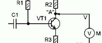
The most common standard instrumentation signal is the 4-20 mA (milliamp) current loop. All textbooks and reference books indicate a 4-20 mA signal. But not everyone understands what this signal is. The correct definition is a change in current in the circuit from 4 to 20 mA depending on changes in the parameters of the measured medium. In essence, it is a variable resistor built into the signal measurement circuit.
Electrical diagram of an analog signal with 4-20 mA current output
Theoretically, it is possible to replace any current sensor with a variable resistor (potentiometer) of about 1 kOhm and set the current we need in the circuit by changing the resistance of the resistor.
To check the measuring channel, you can connect a variable resistor
It is best to install additional resistance on the sensor itself. The entire current loop chain will be checked.
I used this method to check the circuit during commissioning. I set the position of the resistance slider to a position at which the current would be equal to 12 mA. In this case, the readings on the operator panel were approximately 50% of the instrument scale.
Why is this method of checking the functionality of a current loop convenient? During commissioning, the sensor does not yet measure the process parameter. There is no pressure in pipelines or containers. There is also no expense. The sensors output a current of 4 mA (except temperature sensors). Sometimes the current in the circuit may be less than 4mA. Approximately 3.98….3.99 mA. In this case, the operator panel will display as no signal from the sensor.
When connecting a resistance instead of a sensor, a value of ~ 50% will be displayed on the operator panel. The functionality of the measuring channel is checked. At the same time, the correctness of the signal output is checked (in which window on the operator panel the parameter is displayed). The signal record in history is checked. The display of the signal in the saved trends is checked.
Of course, you can use various calibrators to test the sensor, which will more accurately produce the required current. But as usual, there are few calibrators during commissioning. It is necessary to check the performance of a large number of sensors. There are not enough calibrators for everyone. If you use the current calibrator for a long time, the batteries will quickly discharge. In a hurry, you can damage the expensive calibrator. Plus, the two-wire resistor fits in your pocket.
Why was the current set to 12mA, and the instrument readings on the operator’s scale were determined to be 50% of the instrument scale. The calculation is very simple.
If the current in the measuring circuit is 4 mA, the device reading will be 0%. At a current of 20mA, the readings will correspond to 100%. The current range of 20 minus 4 will be 16 mA. Half of the sensor signal will be 16 / 2 will be 8 mA. But since the signal measurement starts at 4 mA, we add 4 mA to 8 mA. Get 12mA. The current is calculated similarly for 25% and 75% of the scale. As a result, we get currents in the circuit: 0% - 4 mA, 25% - 8 mA, 50% -12 mA, 75% - 16 mA, 100% -20 mA.
In a simplified form, I presented a sensor with a 4-20 mA output signal in the form of a variable resistance. But the sensor itself is a very complex device, with its own software, an output signal regulation system, a compensation system for various errors, and a protection system. And if you want to measure the output resistance of a sensor with a 4-20mA output signal, you will not be able to do this. The sensor resistance will show infinity. But you can always measure the current in an analog signal circuit.
Circuit for measuring current in a crossover cabinet
Circuit for measuring current in a junction box.
Current measurement circuit directly on the sensor
5.2.2.2. Analog signal 0 -20 mA
A type of current standard signal is the 0-20 mA signal. The only difference is that when measuring an environmental parameter at 0%, the current signal will be equal to 0 mA. If the parameter of the measured medium matches, the current in the circuit will be equal to 20 mA. Accordingly, at 25% - 5mA, 50% -10mA, 75% - 15mA.
The standard 0-20 mA signal is rarely used in practice. But the ability to switch measurements from a 4-20 mA signal to a 0-20 mA signal is available in many measuring transducers. Also in the settings of the controller's measuring channel. Sometimes it happens that the readings on the controller and the actual values of the parameter of the measured medium do not coincide. For example, the pressure gauge on the pipeline shows 1.2 mPa. And the operator’s monitor displays 0.8 mPa. In this case, the current in the circuit approximately corresponds to the pressure gauge readings. In this case, it becomes clear that in the settings of the measurement channel, the sensor input signal is specified as 0-20 mA. It will be necessary to switch the measuring channel in the settings to measure 4-20 mA.
It would seem, what else can you tell about an analog current signal? Everything seems to be clear. But take your time. There are still some pitfalls in automation systems with current signal measurements.
Classification of instrumentation
Basically, instrumentation equipment is classified according to physical and technical characteristics and qualitative and quantitative indicators. The names of the groups indicate the purpose of the measuring instruments related to them:
- Thermometers can be used to measure temperature. They are: liquid, digital, with resistance conversion, thermoelectric. This group also includes pyrometers and thermal imagers.
- Pressure gauges are responsible for determining pressure: its excess, differential or absolute value. They can be mechanical or electrical contact.
- Flow meters will help measure the flow of the working medium or other substances. This group contains various devices, each of which is focused on controlling and changing a specific material (environment).
- The main function of gas analyzers is to determine the composition of gas mixtures.
- Using level gauges, the filling level of containers is determined.
Devices are designed to measure certain physical properties. Based on these characteristics, they are classified as follows:
- Physical properties (temperature and flame) are monitored by thermometers, thermocouples, temperature sensors and flame monitoring.
- Liquid and gaseous media (pressure, liquid level and flow rate) are measured with pressure gauges, pressure gauges, level gauges, and flow meters.
- Electricity indicators are determined using voltmeters, ammeters, meters, transformer voltmeters, bridges, magazines, ohmmeters and high-frequency meters.
- Analyzers and gas analyzers are chemical meters.
- Radiation levels are monitored using Geiger counters, dosimeters and detectors.
- When monitoring executive automation devices, you cannot do without electric igniters, manipulators and servomotors.
Installation of bales and automation
To install such equipment, it is necessary to have various components: 1. Sensors, measuring instruments, actuators that monitor and control the functioning of mechanical components of the equipment;
2. Controllers that collect information from sensors that control actuators. Using algorithms, they ensure the maintenance of parameters and safe operation of equipment;
3. Means of feedback to the operator through user terminals or building management systems. For this purpose, communication gateways are used. Our specialists install bales and automation, regardless of their complexity. Installation of panels and systems is carried out according to the Customer’s designs, or according to projects developed by our specialists based on the Customer’s technical specifications.
We recommend reading: What is a voltage divider and where is it used?
Installation of automation systems
— Monitoring/control of the operation of units included in the equipment of air conditioning, heating, ventilation, etc. systems; — Indication of the equipment status in operating mode; — Equipment protection from supply voltage connection errors, short circuits, overheating; — Support and regulation of the desired air temperature; — Monitoring the working condition of air filters; — Independent ventilation system control algorithm; — Uninterrupted maintenance of operating equipment; — Supervisory control/management of basic parameters.
Cable system installation
The key to reliable operation of the cable system, which includes power supply, security, and communications, is its high-quality installation. Moreover, the requirements for the reliability of cable systems, their operational safety, and functionality are constantly growing. This is due to the development of modern technologies and the emergence of new high-tech materials.
It is difficult to imagine a modern building without a lighting and uninterruptible power supply control system, without local computer networks, conferencing, security systems and other communications. Other important life support systems of the building depend on the functioning of the cable infrastructure. Ultimately, this is an indicator of the degree of its comfort and functionality.
Carrying out an integrated approach to the process of installing power and low-current networks, our specialists optimize the routes for laying cable systems, taking into account the electromagnetic compatibility of the equipment. As a result, the reliability of the system increases, its maintenance is simplified, and savings in money and time are achieved.
Such results make our services competitive and in demand. The company carries out the full range of work on installation of automation, in detailed accordance with the project, as well as current state standards.
Our specialists will flawlessly install systems for power supply, energy metering, security and fire alarms, access control and management, conference calls, telephone networks, dispatch communications, parking management, etc.
We install bales and automation with high quality, professionally, in the shortest possible time, at a price convenient for our customers.
5.2.2.3. Active analog signal 4-20 mA
When designing, it is not always possible to determine which device will be purchased. Many devices require an additional power connection. Sensors with additional power supply can themselves supply voltage to the connection circuit. Such sensors are called “active current output 4-20mA”. The connection diagram for such a device is shown below.
Connection diagram for a flow meter with active current output
On the diagram I did not indicate the type of power source used. The device can be supplied with either 24V DC or 220V AC voltage. In this case, power is supplied to the measuring module of the analog input of the controller from the device. To connect the device to the controller in this case, it is necessary to use an analog controller module with a passive input.
How to determine the type of 4-20mA analogue output signal on the device? The only way is to measure the voltage by first disconnecting one of the wires from the terminal. By checking the voltage on both sides, you can determine the type of sensor
Why is it impossible to determine the type of sensor signal by the presence of some inscriptions on the “nameplate” of the device, or by the electrical connection diagram? Simply because the same device can have both a passive output signal and an active output signal. The device can be configured using software or by changing the position of the jumpers in the device.
Devices with an active output signal are quite rare in practice. But they apply, and you must remember that.
There is also one type of current signal 4-20mA.
This type of signal is used when measuring flow. Typically, flow rate is measured by multiplying the cross-sectional area by the flow rate through that cross-section. Flow velocity is calculated using various methods. And the cross section is always calculated using the formula S= ∏r². This square in the cross-sectional area formula increases the volume of passing fluid in a quadratic relationship. For example: when the pressure drop changes by 2 times, the volume of liquid passing through a given section will increase by 4 times. When the pressure drop changes by 3 times, the volume of liquid passing through the diaphragm will increase 9 times.
To better understand the difference between current signals with a proportional output signal and a quadratic output signal, I will give an example in the form of drawings. The figures show sections of two types of tape from tape recorders.
Picture 1
In Figure 1 we see that the tape is divided into uniform sections. These lines represent the instrument's scale from 0 to 100%, in 20% increments. The type of this tape is used to record, for example, pressure parameters.
Figure 2
In Figure 2, the scale on the tape is not evenly spaced. Up to 30% the accuracy of the scale is very small. Above 30%, the measurement accuracy increases. This tape is used to record flow parameters.
The current in the pressure sensor and flow sensor circuits will change similarly.
When measuring different parameters, the same device can be used. Let's look at the example of these same two segments of chart strips.
For example, a differential pressure transmitter can be used to measure the differential pressure across a meter line filter.
The same differential pressure transmitter can be used to measure the differential pressure across the diaphragm when measuring flow.
In both cases, the sensor output will be 4-20 mA. But the dependence of the measured parameter on the current value is different.
Let's look again at the example of chart strips.
On the chart strips we see that with the same current of 12 mA there will be different values of pressure drop and fluid flow.
How is the secondary device or controller supposed to “understand” what value it should display?
There is a “root extraction” function for this. This function is enabled in the settings of the measuring channel on the secondary device. When outputting to the controller, a “root extraction” module is added to the channel logic. The actual flow rates will be displayed on the screen.
The “root extraction” function may also be in the settings of flow meters. The operating instructions usually describe everything in detail.
Important. When replacing the diaphragm with a flow meter with a 4-20 mA output, leave the “root extraction” function in only one place. Either on the flow meter or on a secondary device.
Instrumentation devices - classification
Instrumentation and automation equipment is classified according to several parameters, the main of which are physical and technical characteristics and qualitative and quantitative indicators. That is, humidity, temperature, flow, pressure, etc. are measured. Hence the very name of the groups.
- Thermometers.
- Pressure gauges (measure pressure).
- Flow meters.
- Gas analyzers.
- Level gauges.
We recommend reading: Electronic circuits for home and everyday life: description, circuit diagrams of automation and making it yourself
Thermometers are one of the groups of instrumentation and control equipment
There is a group of so-called measuring instruments:
- Radiation measurement.
- Mass, material hardness, density.
- Acoustics.
- Electrical and electromagnetic qualities are measured.
- Physico-chemical composition of the material, its properties.
In turn, for example, thermometers are divided into liquid, digital, resistance conversion, and thermoelectric. This also includes pyrometers and thermal imagers.
Pressure gauges are also divided into several subtypes: excess pressure or its difference, or absolute value, is measured. By design, these are mechanical, electrical contact. Let's add here traditional pressure switches and pressure gauges.
Flow meters are more complex instrumentation and control devices, with the help of which the mass or volume of a material (medium) is determined. This group has a fairly wide range of models, depending on what material (medium) this device will control and measure.
Flow meters - devices for measuring mass or volume
- Vortex, thermal, electromagnetic, ultrasonic, tachometer, correlation, Coriolis.
- With pressure drop, with measurement of level differences, flow measurement.
That is, each device is suitable for certain operating conditions, which are based on the material or environment. By the way, the medium can only be non-electric, because in the control (automation) unit any value is converted into an electrical signal, which is sent for processing. But here the question arises: what about voltage and current in electrical appliances?
The thing is that these two quantities cannot be entered into the controller without preliminary processing, where the output should be an analog signal. After all, the voltage in this case is 220 V. And no automation can withstand it in this form. Therefore, even in electrical networks, sensors are installed. That is, in this case, both current and voltage become non-electric quantities, of course, through an intermediary - the sensor.
5.2.2.4. Analog signals of instrumentation and automation 1-5 V
When using instrumentation with an output signal of 1-5V, the voltage at the sensor output varies - from 1 to 5 V, depending on changes in the parameters of the measured medium. Sensors with such an output signal are used very rarely. But perhaps they are used somewhere else.
But this does not mean that the signal itself is not currently used. Quite a lot of secondary devices with an input signal of 1-5 V are used in petrochemistry. What devices do these secondary devices work with if the sensors themselves are not used?
The standard output signal of 1-5 V is isolated from the current circuit of 4-20 mA. To do this, we connect a precision resistor with a resistance of 250 ohms in series in the current loop. A precision resistor is a high-precision resistor that does not change its characteristics, both from external factors and when the resistor itself is heated to a certain temperature. I don’t really like to insert various formulas on the pages of the site, because no one is interested in them. But in this case, you can’t do without simple formulas. In practice, I came across specialists who had worked for many years in instrumentation and control systems who could not understand this. I will explain in detail.
When drawing up a connection diagram for a 4-20 mA current device, the power supply is usually used with an output voltage of 24 V. That is, If you apply 220V to the input of the power supply and measure the voltage at the output, it will be 24V. This voltage is called the "open circuit" voltage. When connecting a current loop, which also includes a 4-20 mA sensor, the voltage in the circuit will change. When measuring the voltage in the distribution cabinet at the terminals of the current signal circuit, its value will be less. The voltage value depends on the type of sensor, the length of the cable and the current that is currently flowing in the circuit
Let's calculate the magnitude of the voltage drop at the ends of a 250 Ohm resistance. According to Ohm's law, the current strength in a section of the circuit is directly proportional to the voltage and inversely proportional to the voltage. With two known values - current and resistance, we calculate the voltage drop across a resistance of 250 ohms.
The formula for calculating voltage based on Ohm's law is U = I x R. At current: 20 mA - U = 250 Ohm x 0.02A (20 mA) = 5V. At current: 4mA - U = 250 Ohm x 0.004 (4 mA) = 1V.
When a secondary device is connected to the ends of the resistance, we obtain an analog signal with a voltage from 1 to 5 V. This signal will be proportional to the current flowing in the circuit.
When a resistance of 250 Ohms is included in the current circuit of the sensor 0 - 20 mA, respectively, you receive an analog signal of 0 - 5 V.
I think that at this point it is appropriate to offer a solution to a simple comic problem. “What is the current in the socket?” I've heard many different versions. There are usually specialists who claim that 16 A. Others 25 A. Particularly principled ones try to measure the “current in the socket”. Usually this venture ends with the failure of 2-3 multimeters.
To ensure that no one who reads this page “burns” the device, I propose to approach this issue logically. Let's simply insert the values we know into the Ohm's law formula. Let's assume that the current in the outlet is 10A. The voltage in the socket is 220V. We insert this data into the formula. 10 = 220: 0. You cannot divide by 0. Therefore, the “current in the socket” cannot be measured. This is the "Law".. Don't try to refute it.
Why did I make this digression? As I wrote earlier, the operation of all devices is based on the laws of elementary physics. And in order to understand why the device’s readings are incorrect, you need to understand on what principle the device’s operation is based. And if the device showed correctly all the time, and suddenly its readings changed, you need to approach this issue logically.
Let me give you a very simple example. The dishwasher stopped working in the dining room. Electric heaters began to smoke and machine guns were knocked out. There were many speculations about what happened. During test runs, the electric heaters were turned on without water in the sink. The signal to turn on when there was no water level in the sink should have been turned off when the water level in the sink dropped below the top electrode. But this signal did not turn off. The operating principle of the water level alarm was based on the electrical conductivity of water. It was assumed that even in the absence of water, current flows between the electrodes. The sink was rinsed with just clean water. All problems are gone. It remained to find out why electrical conductivity is maintained when water is drained. It turned out that they simply changed the detergent. When the water was drained, an electrically conductive film was formed that allowed current to pass through. We started using the “old” detergent and the dishwasher started working normally.
Conclusion. Changes in the physical properties of the process environment can lead to changes in instrument readings. This is very important for moisture meters, viscometers and other analytical instruments. Therefore, logical thinking is very important for an instrumentation specialist.
Measuring instruments in household appliances
When studying the diagram of any device used in home life (from a washing machine to an iron), you will notice that they are all equipped with devices that measure and control certain parameters:
- hot water - they can be found on boilers or radiators;
- air - relevant for air conditioners and convectors;
- electricity (voltage and current) - similar ones are installed on irons, multicookers, oil heating radiators, etc.
The basis of modern automated systems are microcontroller circuits. In the process of technology development, they replaced control units equipped with circuits with low integration.
Thanks to this, today it is possible to achieve automation of any process, any installation, and even the smallest device.