The definition of KTP in electrical engineering means a complete transformer substation. The concept of completeness in TP is dictated by the design feature of manufacturing - the production of a full-fledged substation for outdoor installation with a set of working units that are assembled in the form of kits into a single power supply system.
Often, a structure consisting of a housing, electrical components for removing and converting energy, and metering panels is delivered to the installation site in a fully or partially assembled form, which reduces time costs and facilitates the installation process and its commissioning.
Purpose of KTP
Modern PTS allow solving several problems at once:
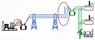
- Reception of electricity from three-phase alternating current power lines with a nominal voltage of 6 (10) kV and an industrial current frequency of 50-60 Hz.
- Stepwise transformation of the received energy into alternating current with a voltage of 380 V (0.4 kV) and a frequency of 50-60 Hz; one phase out of three is allocated for household consumers.
- Distribution of converted electricity to end users connected via a ring (continuous distribution line in the form of a closed loop) or radial connection scheme.
The capacities of power electrical installations are designed to supply energy to medium and large consumer facilities, including:
- construction sites;
- industrial enterprises;
- residential areas, microdistricts, villages;
- communal and municipal services;
- agricultural and farming facilities.
A wide variety of designs, configurations and structures that fit most correctly into the climatic and technical operating conditions of the complete device allow you to choose an option suitable for a specific facility.
Selection principles
Electrical systems use substations with one or two power transformers. PTS with three power units are used very rarely, only in forced situations, as this causes unnecessary costs.
Typically, such a scheme is used for separate power supply of power and lighting equipment or to provide electricity to objects during sudden changes in loads. At large substations, experts try to use only two transformers to provide consumers with a more reliable power supply.
You might be interested in this: How to decipher the abbreviation KIPiA and what does a Kipovets do?
When a production facility uses several places for power supply or provides electricity according to a more complex input scheme, then the use of one power transformer is allowed. When supplying electricity via main lines, substations are recommended to be connected to different circuits, provided that there is a reserve.
Operating conditions for complete transformer substations
Full uninterrupted operation of the installation with minimal losses during the transmission of electricity is possible subject to the rules of installation, commissioning and conditions corresponding to the climatic design in accordance with GOST 15150 U (moderate) or UHL (moderately cold):
- operating temperature range from -45°С to +45°С (for current converters with oil insulation);
- operating temperature range from -1°С to +40°С (for current converters with dry insulation);
- atmospheric pressure – 86-106 kPa;
- relative air humidity – up to 80% (at air temperature up to +20°C);
- wind gusts up to 36 m/s.
KTPs are designed to be located at an altitude of up to 1 km relative to the sea line. In practice, there are isolated cases of exceeding this parameter, but manufacturers are not responsible and do not provide warranties for such situations.
It is strictly forbidden to operate the installation:
- during seismic activity;
- in explosive environments;
- when there is dust in the air that transmits current discharges;
- under conditions of a high content of chemically active volatile compounds and vapors, which have a destructive effect on the metal and insulating materials of the product.
Installation work consists of placing a pre-assembled and factory-assembled station, equipped with dedicated transport and lifting devices, on a flat surface made of brick or concrete. Before commissioning, a final audit of all power plant complexes is carried out. The service life of the unit is at least 25 years.
Definition of CTP
KTP is one of the main components of the power supply system. These installations are used for receiving, converting and subsequent distribution of electricity. At the same time, they ensure minimal losses in electrical conductors.
The main feature of the PTS is its completeness - this means that all the working units and devices of the substation are already assembled into a single system and are ready for connection to the power supply network and operation. The structure, which includes the housing, power conversion devices, switching equipment and measuring devices, is usually delivered to the installation site ready or partially assembled. This allows you to reduce installation time, simplify and speed up the commissioning of package transformer substations.
Symbols of KTP
Explanation of symbols includes the following parameters:
- type of execution;
- connection type;
- transformer power;
- letter designation of the product;
- classification of input from the HV side;
- classification of output from the LV side;
- number of transformers used;
- HV voltage ratings;
- LV voltage ratings;
- climatic implementation according to GOST 15150 and placement category.
Manufacturers reserve the right to change (add or delete) some product data.
General characteristics
PTS are traditionally used in power supply complexes for the own needs of consumers, manufacturing companies, as well as mines. If we take into account two-component substations, then we must take into account that they have a sectional module that includes two inputs, including from a diesel power plant (diesel power plant).
The environment must meet the following requirements:
- Explosion proof.
- It should not contain vapors and gases that are hostile to insulating materials.
- Electrically conductive dust must be absent.
Device
The usual configuration of power supply devices consists of 3 components. All of them are located in a metal body, a welded body made of sheets and profiles. It houses the HVN (high voltage device), RUNN—low voltage switchgear, and the transformer itself.
To carry out maintenance, electricians enter the premises through swing gates. All electrical connections are made using bus connections or flexible connections. The KTP also includes a device for external inclusions and other components that support the necessary parameters.
External transformer points, unlike KTPM (mast-mounted substations), have a much wider range of capacities. This makes it possible to use external complete devices in a wide range of applications, and there are also samples with 25-4 thousand kilovolt-ampere characteristics.
Commissioning
The normal operation of the KTPN is determined by the organization of installation work prescribed by special standards. The manufacturer has the opportunity to deliver the device to the site of operation either block-by-block or completely assembled. On the front side there is an assembly diagram.
Transport elements are ready for installation work. There is no need to disassemble the switching equipment. The reliability of hidden connections is checked before assembly begins. Assembly components are equipped with special devices for the use of lifting mechanisms when moving and lifting. The assembled substation is placed on a flat surface. Before use, tests of all electrical substation complexes are organized.
Completeness
The range of devices and systems for installing a CTP pump is varied. Most used components:
- Lighting. Different types of lamps can be used. It includes outdoor and emergency lighting.
- Ventilation system. Both natural and forced ventilation are used. With its help, equipment is protected from overheating and moisture accumulation is prevented.
- Heating systems. The most commonly used convector heating system, manual or automatic.
- Fire and security alarms. It is displayed on the central security console and connected to external alarm equipment.
- PPE. Ensure safe work performance.
The list of tools used is adjusted according to the customer’s wishes..
KTP design
Traditionally, a package transformer substation is a set of component parts distributed in localized modules, which are combined into a common housing. Based on their structural components and location, stations are divided into ground-based, mast-based and integrated. The first ones are equipped in cases made of metal, reinforced concrete or insulated sandwich panels. Mast ones are placed on vertical poles and can have a lightweight metal structure with partially open elements. To make technical work accessible, a special staircase and platform are provided.
To service the station there are doors or swing gates with a central lock and a locking system. The body is equipped with technical openings and hidden blinds to organize natural thermoregulation and ventilation of the system.
Optional equipment
To connect a transformer substation using a cable over the air to the nearest power line, use the following equipment for air entry:
- post, pin and bushing insulators
- voltage limiters
The chamber itself, the high entry portal, is mounted on the roof of the package transformer substation using bolts above the RUVN or RUNN compartment.
To ensure the safety of people servicing the transformer substation, a grounding loop is provided on it. His absence from the substation is unacceptable. It is a metal strip connected to the ground and extending 40-50 cm into it, non-current-carrying parts that serve to remove stray electric currents from the system, and also prevents the accumulation of static electricity on the electrical equipment of the substation.
Types of package transformer substations
CTPs come in different types and types, and therefore can also differ significantly from each other. Complete transformer substations are classified into the following types:
- KTPN. These substations are manufactured only for outdoor installation (kiosk type). Their power can reach 10-2500 kVA, and the voltage can vary in the range of 6-35 kV.
- 2KTPN. The design of this substation is similar to the previous one, but the main difference is the presence of not one, but two transformers, allowing the substation to operate more efficiently.
- KTPU and 2KTPU. Substations of this type have so-called sandwich panels that insulate them. Due to this, the equipment can be used in conditions of low temperatures – down to -60 degrees Celsius.
- KPTM. Mast substations that serve to supply energy to oil wells and small settlements.
- KTPS. Pole models are usually mounted on metal or reinforced concrete structures. They are used mainly on agricultural sites or holiday villages.
- KTPV. This type of substation is intended for indoor installation. Such models find their application in manufacturing enterprises.
This is what actually distinguishes one type of QTS from another type of QTS.
Specifications
Complete transformer substations are designed to receive, distribute and convert alternating current electricity. Technical specifications of the package transformer substation:
- The ambient temperature should be approximately from -40 to +40 degrees for an oil transformer and from -1 to +40 degrees for a dry transformer.
- The KTP must be installed so that it does not exceed more than 1000 meters above sea level.
- The ambient air humidity should be somewhere around 20 degrees Celsius.
- The environment should not be a fire hazard.
- The speed of the headwind is no more than 36 meters per second.
- Service life - more than 25 years.
In this article we will look at what a PTS , what kind of PTS there are, what they are intended for, what is their design difference and why there is confusion in their types. For an accurate understanding, we will need the following definitions: clause 4.2.6 (PUE Seventh Edition): Transformer substation (TS) is an electrical installation designed for receiving, converting and distributing energy and consisting of transformers, switchgear, control devices, technological and auxiliary structures. clause 4.2.10 (PUE Seventh Edition): KTP - complete transformer substation - substation, consisting of transformers, units (switchgear switchgear and switchgear switchgear) and other elements supplied assembled or fully prepared at the manufacturer for assembly. A large selection of standard substation solutions is presented in our “ Regulatory Base ” in the corresponding section . The definitions are quite accurate and comprehensive, however, it is common to hear that when it comes to package transformer substation, carried out according to standard specifications from MOESK, the talking parties imagine different devices. So that all parties see the same picture, let's consider variations of QFT.
The most common TP for individual buildings, villages, individual plots is MTP . The mast transformer substation is the cheapest transformer substation, often called “Collective Farmer” because of its low cost and extremely simple design. The appearance and possible dimensions of the MTP are presented in the figure below: MTP is an open transformer substation, all of the equipment of which is installed on structures (including two or more racks of overhead line supports) with a service platform at a height that does not require fencing of the substation. In this case, it is important to note that this type of substation does not require fencing of the substation. MTP is often performed in sizes from 25 kVA to 250 kVA .
An equally common TP for power supply to plots, individual cottages and other consumers up to 63 kVA is STP (OSTP) . STP (OSTP) - Pole (Single-Pole) transformer substation is a type of collective image of a package transformer substation; the most common type is STS assembled on one support. The appearance and possible dimensions of the STP (OSTP) are presented in the figure below:
STP equipment:
1. Transformer. 2. Cabinet RUNN. 3. Fuse. 4. Valve arrester (surge suppressor). 5. Cross beam 0.23 kV. 6. Cross beam 10 kV.
STP (OSTP) is an open transformer substation, all the equipment of which is installed on a single-column overhead line support at a height that does not require fencing of the substation. STP (OSTP) is often performed in sizes up to 63 kVA .
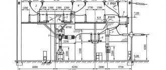
The next segment is more expensive PS. KTPSH - A complete cabinet-type transformer substation is a type of KTP; the most common type is KTPSH assembled on 4 stepsons (USO racks) with the presence of a RUNN and UVN cabinet. Unlike previous variations, KTPSH requires a fence; as a rule, it is mesh. The appearance and possible dimensions of the KTPSh located on the stepsons (USO racks) are shown in the figure below:
KTPSH equipment : 1. Transformer. 2. Fuse cabinet. 3. Cabinet RUNN. 4. Protective casing for transformer terminals. 5. 10 kV bushing insulator. 6. Pin insulator 10 kV. 7. Valve arrester (surge suppressor). 8. Rack USO 3A, length 3600mm.
This article covers most of the variations of QTP, but not all; gradually the article will be supplemented with new, less common TP. Continuation of the article - KTPTAS (KTPPAS), KTPGS, KTPN , KTPNU You can discuss this article on our forum, your opinion and your vision of the situation are very important to us