Thermocouple
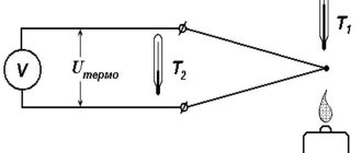
Structurally, a thermocouple consists of soldering two wires of different metals. The temperature difference between the hot and cold ends provokes the appearance of an emf in the circuit, the magnitude of which depends on the material and thermoelectric force of the thermocouple and can be from 40 to 60 μV. Combinations of nickel-chrome, chromium-aluminum, iron-nickel, iron-constantan and others are used as thermocouple materials. The thermocouple provides high accuracy, but measuring this accuracy is problematic. Being a relative sensor, a thermocouple has a voltage level dependent on the temperature difference between the junctions. The cold junction usually has the temperature of the environment in which it is located. If we delve deeper into the principle of operation of a thermocouple, it looks like this: at the hot and cold ends of the thermocouple there are two temperatures, the difference of which determines the emf. The cold junction temperature must be compensated. A solution to this problem in a hardware environment is to use a second thermocouple placed in an environment with a previously known temperature. The software environment uses a different, absolute temperature sensor placed in an isothermal chamber along with the cold junctions. Such a sensor controls the temperature of the junctions with a specified accuracy. When working with a thermocouple, there are a number of difficulties that accompany taking data from the sensor:
- Thermocouple nonlinearity
. To convert the EMF value to temperature and vice versa, high-order polynomials are used, prescribed in GOST - The thermo-EMF values
obtained from a thermocouple are small, on the order of units and hundreds of microvolts, which makes it impossible to use conventional analog-to-digital converters. To obtain undistorted data from the thermocouple, precision multi-bit, low-noise analog-to-digital converters are used
Pyrometers (thermal imagers)
A non-contact type of thermal sensors that read radiation that comes from heated bodies. This type of device allows you to measure temperature remotely, without getting close to the environment in which the measurements are taken. This allows you to work with high temperatures and very hot objects without dangerous proximity.
All pyrometers, based on their operating principle, are divided into interferometric, fluorescent, and sensors based on solutions that change color depending on temperature.
Thermistors
A simpler and more common device for measuring temperature is thermistors. Their work is based on the principle of dependence of the resistance of materials on external temperature. Metal resistance thermometers, especially platinum ones, provide high accuracy and linearity of measurements. The main characteristic of a resistance thermometer is the base resistance of the thermometer at a certain temperature. According to GOST, resistance at zero degrees Celsius is considered basic. GOST recommends using several resistance values in Ohms and a temperature coefficient, which is determined by the formula: Tc = (Re – R0c)/(Te – T0c)*1/R0c,
Where
Re
is the resistance at our temperature;
R0c
– resistance at zero degrees;
Te
is our temperature;
T0c
– zero temperature. GOST thermistors contains temperature coefficients for various thermometers made of platinum, copper and nickel and polynomial coefficients for calculating temperature from the current resistance of the resistor. Although resistance thermometers have a small temperature coefficient of resistance, it is easier to obtain high accuracy when measuring resistance than when measuring small voltage values when working with a thermocouple. To measure resistance, a thermal resistance is connected to the current source circuit, after which the differential voltage is measured. The temperature coefficient when using semiconductors will be a fraction of a percent. For such measurements, analog-to-digital converters are used. Temperature sensors implemented in the form of integrated circuits are equipped with an analog output corresponding to the supply voltage. To digitize the signal from such sensors, eight- or ten-bit ADCs are used.
Main signs and characteristics of DTOZh malfunctions
The failure of the coolant temperature sensor can be judged by several signs. However, it is worth understanding that the typical manifestations listed below may also be the cause of other car engine defects. Therefore, to be sure, you need to conduct an additional check.
The main signs indicating a sensor malfunction:
- The Check Engine light came on on the dashboard. If you see this icon, scan the error code; it may indicate other problems.
- Fuel consumption has increased. Due to the fact that the electronic unit receives incorrect data from the sensor, it cannot correctly read it and determine the required command. Namely, how much fuel is needed to form a fuel mixture and maintain the optimal engine temperature.
- Unstable engine operation. This includes failures at idle, difficulties when starting the engine (more often in winter) or a complete stop at low speeds.
- The car stalls when the engine is warm. As soon as the antifreeze temperature reaches a certain point, the engine stops spontaneously. Regardless of what liquid was used in the system (good antifreeze or plain water).
- Unstable fan operation. There are several manifestations - sometimes it does not work at all, and in other cases it does not switch to emergency mode. Here it is important to additionally check the thermistor for serviceability.
- The car does not start easily when the engine is cold.
More often, such sensors are made with a non-separable housing, so if they are defective, they are replaced with new ones. This applies to cars of any manufacturer, both domestic and foreign.
Quartz temperature converters
If it is necessary to expand the range of measured temperatures, quartz converters are used. They allow measurements in the range from -80 to +250 degrees Celsius. The principle of their operation is based on the frequency dependence of quartz on temperature. The function of the converter varies depending on the location of the cut along the crystal axes. Quartz sensors provide high sensitivity and measurement resolution, coupled with operational stability. Due to these properties, quartz sensors are widely used in digital thermometers.
Where to find the sensor on the car
To check the sensor you need to know where it is located. Naturally, its location will differ in different brands and models of cars. However, there are several signs by which you can determine where it is installed.
Most often, the coolant temperature sensor is located on the outlet pipe of the cylinder head. Its design includes a thread with which it is mounted in the appropriate place. An important requirement is direct contact of the sensor head directly with the coolant. This provides the most accurate sensor readings.
It should also be taken into account that some car models have two coolant temperature sensors at once. In such cases, the first one takes and transmits readings of the antifreeze temperature at the engine outlet, and the second one at the radiator outlet. This provides more accurate information about the condition of the engines and cooling systems.
All information about the number and location of sensors can be found in the car’s registration certificate.
Noise temperature sensors
The operation of noise temperature sensors is based on the dependence of the noise potential difference across the resistor on temperature. In practice, to measure temperature with noise sensors, you need to compare the noise of two identical resistors, one of which is located in an environment with a known temperature, the second in an environment whose temperature needs to be measured. The temperature range that can be measured using noise sensors is from -270 to +1100 degrees. The main advantage of noise sensors - the ability to measure temperature in thermodynamics - is complicated by the extremely low noise voltage, comparable to the self-noise level of the amplifier. This makes noise voltage extremely difficult to measure.
Comparison of temperature sensor types
The table below shows a comparison of the different types of temperature sensors discussed in this article.
However, keep in mind that this information should be taken as a generalization. The table is intended primarily for those who do not have much experience and/or knowledge about temperature sensors. Table 1. Brief comparison of temperature sensors
| Sensor type | Typical Temperature Range (°C) | Accuracy (+/- °C) | Advantages | Flaws | Application |
| Thermistor |
| 1 |
|
| Ambient temperature measurement |
| Thermocouple | -200° to 1450° | 2 |
|
| Industrial use |
| RTD | -260° to 850° | 1 |
|
| Industrial use |
| Analog chip | -40° to 125° (TMP36) | 2 |
|
|
|
| Digital chip | -55° to 125° (DS18B20) | 0,5 |
|
|
|
Original article:
- Nick Davis. Introduction to Temperature Sensors: Thermistors, Thermocouples, RTDs, and Thermometer ICs
NQR temperature sensors
Functioning of NQR thermometers
– nuclear quadrupole resonance, occurs due to the action of the field gradient of the crystal lattice current and the nuclear moment, which is caused by the deviation of the charge from the symmetry of the sphere. This creates a procession of cannonballs. The frequency depends on the grating field gradient and for different substances can reach thousands of megahertz. The gradient depends on temperature, with an increase in temperature, the NQR frequency decreases. Structurally, NQR temperature sensors are an ampoule with a substance placed in an inductance winding connected to a generator circuit. When the generator frequency matches the NQR frequency, the generator energy is absorbed. When measuring a temperature of -263 degrees, the tolerance is ±0.02 degrees, and at 27 degrees - ±0.002 degrees. Despite the significant nonlinearity of the conversion function, NQR thermometers have unlimited time stability.
Types, design and operating principles
Thermocouple
The sensor includes two wires made of different metals, soldered together. To keep the ends in contact with each other in a constant temperature zone, extension wires made of two metals are added to the design. When the ends of the wires are exposed to different temperatures (for example, when placing the sensor in hot water), an electric current appears in the circuit. The strength of the generated current (from 40 to 60 μV) depends on the thermocouple material used, which affects the thermoelectric force of the device.
In practice, you can find iron-nickel, chromium-aluminum, copper-constantan, and so on. Cheap models use base metals (similar to thermoelectrodes) for extension wires, and expensive ones use noble metals, which are able to develop a similar thermo-EMF as the electrodes (necessary to reduce the cost of high-end devices).
Thermocouple is a high precision sensor. The problem with the device is the difficulty of obtaining the measured value. The thermocouple operates on the principle of relativity of temperature differences between the connectors. The hot junction is placed in the substance being measured, and the cold junction remains in the environment.
If it is necessary to use a thermocouple, the work is carried out as follows. The temperature of the cold junction must be compensated, for which the second thermocouple is placed in an environment with a known indicator.
If software compensation is used, the second sensor is placed in an isometric chamber where the cold junctions are located, allowing the temperature to be controlled with high accuracy. The most difficult thing in working with a single-contact thermocouple is taking readings.
GOST specifies the coefficients necessary to convert EMF into temperature and vice versa. Counting can also be done using a controller.
But the EMF indicator obtained from a thermocouple is measured in units and hundreds of microvolts. Therefore, the use of analog converters will not be successful. To assemble a special design, the purpose of which is to obtain accurate results, low-noise analogue converters will be required.
In practice, to eliminate existing errors, automatic correction for the temperature of the free ends is used. This means the introduction of a bridge with shoulders in the form of copper and manganin thermistors.
Thermistors
Thermistors are divided according to the type of dependence of resistance on temperature. They can be negative (NTC) or positive (PTC).
Measurements are easier to carry out using thermistors. The operating principle is based on the resistance of materials to external temperature. High accuracy is inherent in devices made of platinum. The operation of thermistors is affected by two characteristics.
The first is the base resistance, the second is the temperature at which it is determined. GOST states that the determination must take place at 0 degrees Celsius. The regulatory document states that it is recommended to use several resistance values, defined in Ohms, as well as temperatures, which will allow the results to be compared at 0°C and another indicator. The following formula is used for this:
Tc = (Re – R0c) / (Te – T0c) *1/R0c
The temperature coefficient will vary depending on the material used for thermometers, which is reflected in GOST. The regulatory document also indicates the polynomial coefficients required for the calculation depending on the current resistance.
Resistance thermometers have one drawback - a low temperature coefficient of resistance. Despite this nuance, the use of thermistors is simpler compared to the operating principle of a thermocouple.
Measurement methods will depend on the model configuration. Basic thermistors must be connected to a circuit with a source of current and a controlled differential voltage. To correctly determine the fractions of a unit of percent obtained from the temperature coefficient of conductors, it is better to use analog-to-digital converters.
If the sensor already has a built-in analog output corresponding to the supply voltage, then for digitization you can directly connect the thermistor to the converter
Combined
Combination sensors involve multiple semiconductors combined into a single device. Sensors can have a built-in digital interface rather than just integrated circuits with output. A combination sensor is often used due to the ability to connect parallel devices. The error when calculating temperature is 2 °C, and when determining humidity – 5%. There is only one problem with such a sensor - interface optimization.
Digital
Digital sensors use a three-pin microcircuit. Indicators are read from several parallel working sensors, which allows you to obtain readings with an accuracy of 0.5 °C. The electronic thermometer can operate from -55 to +125 °C. The only disadvantage of the device is the speed of obtaining results - 750 seconds to obtain the most accurate indicator. Determining the accuracy of the device is carried out using appropriate adjustments, which are necessary to reduce the amount of time spent on obtaining the result. Polling the sensor does not make sense, since the housing is inertial.
Contactless
The operation of the sensor is based on heating a thin film, which is carried out by exposure to infrared rays. You can find a similar technology in pyrometric devices. Unlike contact, data can be obtained at a distance.
Quartz temperature converters
If the range of variable temperatures exceeds standard values and reaches from -80 to +250°C, then quartz converters are used. Such devices operate on the principle of interaction between quartz and temperature, reflected by frequency dependence. The converter has several functions that change depending on the location of the cut along the crystal axes.
Quartz sensors are characterized by high accuracy, stability and resolution. They are more promising ways to measure temperature. Often found in digital thermometers.
Noise
The noise sensor is used to obtain indicators based on the principle of potential difference across a resistor, which changes depending on temperature. In practice, such a measurement method has a condition - one of the temperatures must be known, and the second must be measured. The two resulting noises from different temperatures are compared and the desired value is found.
The sensor can operate from -270 to +1100 °C. One of the advantages is the ability to measure temperatures in thermodynamics. But the downside is the difficulty of implementing this method of measuring voltage with noise due to differences with the noise of the amplifier.
Nuclear quadrupole resonance
The operating principle of a bimetallic thermometer is based on the action of the field gradient of the crystal lattice current and the nuclear moment caused by the deviation of the charge from the symmetry of the sphere. By this process a procession of nuclei is created. The frequency directly depends on the grating field gradient. Depending on the substance, the value of the indicator can rise to several thousand MHz. The higher the temperature, the lower the NQR frequency.
NQR forms an ampoule with a substance, which is placed in the inductor winding for further connection to the generator circuit. If the generator frequency and the NQR frequency coincide, then the energy emanating from the generator is absorbed. When measuring a substance with a temperature of -263°C, the error is 0.02 degrees, and at a temperature of 27°C, the error is 0.002 degrees. The advantages of the sensor include constant stability. The downside is the significant nonlinearity of the transforming function.
Volumetric transducers
The operating principle of another type of bimetallic thermometer is based on the property of substances to expand and contract depending on the current temperature. The operating range of the transducer is determined depending on the stability of the material. The sensor can be used at temperatures from -60 to +400°C. The error will be from 1 to 5%.
When determining temperature with liquid sensors, the error drops to 1-3% depending on the temperature environment. The boiling and freezing temperatures of the liquid will also affect the operating interval of the sensor.
If the sensor measures gas transducers, then the measurement limit depends on the point at which the gas transitions to the liquid state and the resistance of the cylinder to the operating temperature.
Duct
All digital thermometers are channel thermometers, since they use channels to transmit signals. Depending on the number of such “highways”, the channel capacity of the device is determined. Thus, the Testo 925 thermometer is a 1-channel thermometer; its operation is based on a thermocouple, just like the Testo 735-2 thermometer is a 3-channel thermometer. And Testo 810 is a 2-channel device with an infrared thermometer.
Volumetric transducers
The property of substances to expand and contract with temperature changes has found application in volumetric sensors. The range of measured temperatures depends on the stability of the properties of the materials. Typically this range is from -60 to +400 degrees Celsius with a tolerance of 10 to 5%. When working with liquid, the sensor interval depends on the boiling and freezing points. At the same time, the measurement error ranges from 1 to 3% and depends on the temperature of the environment. The lower limit of measurements when working with gas is determined by the temperature at which the gas transitions to the liquid state, the upper limit is determined by the resistance of the cylinder to temperature.
Semiconductor temperature sensitive elements
Although I make thermistors from semiconductor materials, here we are talking about the effect of temperature changes on the pn junction of transistors and diodes. These devices are characterized by a temperature voltage coefficient - TKN. This is the change in applied voltage with temperature change. For all semiconductors, its negative value is approximately 2 mV/0C.
Based on semiconductor temperature sensors, specialized microcircuits are produced in which a temperature-sensitive element, signal amplifiers and stabilization circuits are placed on one chip. Currently, such microcircuits are widespread and are produced in millions of units by many manufacturers. And the consumer receives a finished calibrated product with an output signal of the required value and the required error (accuracy). Microcircuits such as temperature sensors are used in a wide variety of devices.
Another application of semiconductor thermal sensors is as stabilization and compensation elements in electronic circuits. For example, when current flows through powerful power elements, it heats up, the resistance and, accordingly, the parameters change, to compensate for this effect, a thermal transistor is attached to its body and included in the thermal compensation circuit.
Thermal relays are devices for turning on or off the load when a certain temperature is reached; they convert thermal energy into mechanical energy, which is used to close/open electrical contacts.
The scope of application of these products is automation and protection of devices in everyday life, in production, in cars. For example, they are used in irons, heat curtains, and electric fireplaces. Their main advantage is their low price and simplicity.
They produce adjustable thermal relays configured for a specific response temperature. With make and break contacts, as well as with groups of contacts for making/breaking at the same time.
Technical parameters of the thermal relay:
- response temperature - the temperature upon reaching which the relay contacts close/open
-return temperature, respectively, at which a return to the original state occurs
- hysteresis (differential) - difference between response and return temperatures
-switched current and voltage, the durability of the device depends on this parameter, it is worth selecting a device with a current reserve
- contact resistance
- response time
-device error, for example +/- 10%
Design and principle of operation
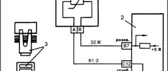
The DTOZh temperature sensor is a resistor (thermistor) that reacts to the temperature of the antifreeze in the engine cooling system. Information about the resistance of this element is transmitted to the ECU, which decides to change the settings in the engine operation.
The information obtained is used by the ECU to determine the steps of the idle speed regulator to optimally adjust the required volume of the fuel mixture.
The peculiarity of DTOZH is that in the cold its resistance increases, and when heated, on the contrary, it decreases.
So, when reaching 130 degrees Celsius, the resistance parameter is 70 Ohms, and at minus 40 degrees - 100.7 kOhms.
The thermistor is controlled by applying +5 V voltage to it from the controller.
The potential passes through a classical resistor with constant resistance (R).
The antifreeze heating level is calculated based on the voltage drop across the DTOZh with variable R (Ohm). In this case, the drop will be large on a cold engine, and low on a warm engine.
Checking the removed DTOZH
For a more accurate check, it is recommended to remove the device from the vehicle. To do this, you need to let the engine cool, and then drain the coolant from the system.
To remove it, you only need a key “19” (20, 21, 22), with which you can unscrew the sensor and remove it together with the ring.
At the same stage, it is worth assessing the condition of the device itself, its threads, cleaning and lubricating it.
The same operations can be done with respect to the sensor itself. After dismantling is completed, you can proceed directly to work.
Checking with a thermometer
After dismantling, you can check with a thermometer. This option provides the most accurate information, so it is recommended for most cases.
The algorithm of actions is as follows:
- Prepare a vessel and pour water into it.
- Use a boiler to heat water.
- Prepare your multimeter for measurements.
- Immerse the sensor element in the liquid.
- Provide the ability to connect a multimeter to the contacts.
- Place a thermometer in the water to monitor the temperature. It is better to use the electronic version, which provides greater accuracy.
- Heat the water and take measurements for different temperatures, for example, from +5 degrees Celsius and above in steps of “5”.
- Fill out the table containing the resistance parameters in relation to the set temperature.
- Check with the information provided in the vehicle manual.
Of course, inaccuracies may occur during the measurement process. The error depends on several factors: operating conditions and the characteristics of a particular DTOZH. In particular, even in devices of the same model, the resistance parameter may differ.
Without thermometer
If desired, checks can be made without using a water temperature meter.
In this method, you can act according to the principle discussed above, but with minor restrictions.
The general algorithm is:
- Boil the water.
- Install the DTOZh sensitive element into it.
- Measure the resistance at the terminals.
At a temperature of about 100 degrees Celsius, the resistance should be about 177 ohms. But here you need to take into account possible errors.
In particular, at the time of measurements, the temperature may change downward.
The disadvantage of the method is that the test is performed only at one temperature point.
How to check the DTOZH using the example of a VAZ 2110
In general, the coolant temperature sensor on different VAZs is checked using the same methods and in the same sequence as described in the previous sections. Most often, sensors with article numbers 23.3828 and 405213, or its analogues – 423.3828, are installed on Ladas 2110, 2112, Priora, Kalina and others.
To carry out the test, you need to know what its resistance is at different temperatures:
- 15 °C - from 4,033 to 4,838 Ohms;
- 128 °C - from 76.7 to 85.1 Ohm;
— output voltage at 15 °C – from 92.1 to 93.3% of that supplied from the ECU;
— output voltage at 128 °C – from 18.1 to 19.7%.
Before dismantling the DTOZh for subsequent inspection or replacement with a new one from the cooling system, it is necessary to drain the antifreeze a little. This is done on a cooled engine to avoid injury and damage to engine parts or tools.
The sensor is unscrewed with a 19 mm wrench. To do this, unscrew it and remove it together with the sealing ring.
Measurements are carried out in steps of 10 °C from the boiling point to room temperature. The resistance values are recorded and finally checked against the table.
Scope of application of thermostats with sensor
Thermostats with a temperature sensor are universal devices. They can be used when installing a heating system in any room with the possibility of installation on various surfaces. We invite you to familiarize yourself with the area of use of thermostats.
Thermostats have a wide range of applications
Air temperature sensor for heating boiler
The heating system needs constant monitoring. Using a special air temperature sensor for a heating boiler, you can monitor the increase in water volumes and current information. If there is a deviation from the regulatory requirements, measures can be taken to restore the system's functionality.
Such devices allow you to monitor the degree of heating of the coolant in certain areas. With their help, you can automate the operation of the heating system. To do this, at the design stage, the correct model of the heat sensor is selected, taking into account the design features and characteristics of the heating equipment.
They can be installed in various places, connecting directly to the elements of the heating system, or located at some distance. The latter type is mounted together with room thermostats. Wireless sensors that allow you to collect information using auxiliary electronics are quite popular. Possessing a large error, they allow installation in any place where the signal can reach. Wired ones use wires to transmit signals. This significantly improves measurement accuracy.
Each boiler has its own model
Thermostat in a socket for household heaters
Mobile thermostat that can be installed on any outlet. Due to its design features it is an adapter between the socket and the heater. A plug-in thermostat for household heaters is relevant for any type of equipment. It is suitable for oil, spiral and quartz instruments.
Attention! When choosing a thermostat, you should focus on the power of the device.
Installation of the thermostat must be performed according to certain rules:
- the block must be located at a distance of at least 0.4 m from the floor surface. Better - 1.5 m, if there is such an outlet in the room;
- the distance between the heater and the thermostat is selected in such a way as to prevent overheating of the unit;
- Direct exposure to sunlight should be avoided;
- it is worth providing protection from external influences. Especially if there are small children in the family.
Attention! If you plan to use an electrical system to heat the house, even at the design stage you should decide on the location of outlets for thermostats.
The thermostat will prevent the heater from overheating
Main models
- DS18B20.
A budget model with good accuracy. It uses 1-Wire for connection, which allows you to connect meters over a three-wire line.
- LM75A.
Has a fixed conversion time. It has the ability to connect up to 8 devices per bus. Accurate to 0.125 degrees Celsius.
- STTS75.
Just like the LM75A, it has the ability to connect up to 8 devices, while it has a higher operating speed than the DS18B20, thus collecting the best from all models.
