Potential difference
Voltage on a non-uniform section of the circuit
(where there are external forces) is equal to the sum of the source emf and the potential difference in this area:
For a homogeneous chain section
, where outside forces do not act,
Those. the voltage coincides with the potential difference at the ends of the circuit section
.
- Ohm's law for a homogeneous section
of a circuit in integral
and differential
form
. Resistance and its dependence on temperature. Superconductivity.
Ohm's law for a homogeneous section
of a chain in integral
and differential
form
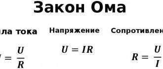
Ohm's law for a homogeneous section of a chain: n
German physicist Georg Ohm experimentally established that the current strength in a circuit is directly proportional to the applied voltage and inversely proportional to the resistance of the conductor:.
Ohm's law in differential form (Ohm's law for current density).
Ohm's Law form applies to the entire conductor.
Let us present Ohm's law in differential (i.e., relating to a current element of length dl
) form.
A certain point inside the conductor is characterized by the current density vector, the electric field strength, and the properties of the conductor material, i.e. specific resistance. Let us mentally select a small volume near the point in question and substitute it into Ohm’s law, we obtain: ,
here is the potential difference between cross sections
dS
separated at a distance
dl
. Hence,.
Let's take into account that - electrostatic field strength; - electric field density; - electrical conductivity.
Then formula (20) implies Ohm’s law in differential form
: .
Electrical circuits. Electromotive force
An electrical circuit
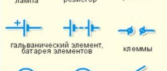
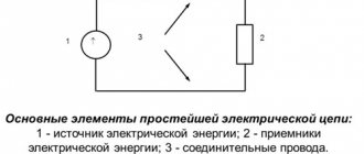
consists of a current source, electricity consumers, connecting wires and a key that serves to open and close the circuit and other elements (Fig. 1).
Rice.
1 Drawings that show ways of connecting electrical devices in a circuit are called electrical diagrams
. Devices on the diagrams are indicated by symbols.
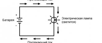
As noted, in order to maintain electric current in the circuit, it is necessary that at its ends (Fig. 2) there is a constant potential difference φ
A -
φ
B. Let at the initial moment of time
φ
A >
φ
B, then the transfer of a positive charge
q
from point
A
to point
B
will lead to a decrease in the potential difference between them.
,
it is necessary to transfer exactly the same charge from B
to
A. If in the direction A
→
B
the charges move under the influence of the forces of the electrostatic field, then in the direction
B
→
A
the movement of charges occurs against the forces of the electrostatic field, i.e. under the influence of forces of a non-electrostatic nature, the so-called third-party forces. This condition is satisfied in the current source, which supports the movement of electrical charges. In most current sources, only electrons move; in galvanic cells, ions of both signs move.
Rice. 2
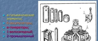
Sources of electric current may vary in design, but in any of them work is done to separate positively and negatively charged particles. Charge separation occurs under the influence of external forces
. Third-party forces act only inside the current source and can be caused by chemical processes (batteries, galvanic cells), the action of light (photocells), changing magnetic fields (generators), etc.
Any current source is characterized by electromotive force - EMF.
The electromotive force
ε
of a current source is a physical scalar quantity equal to the work of external forces in moving a unit positive charge along a closed circuit
\(~\varepsilon = \frac{A_{stor}}{q} .\)
The unit of electromotive force in SI is the volt (IN).
EMF is an energy characteristic of a current source.
In the current source, in the process of separating charged particles, a transformation of mechanical, light, internal, etc. occurs. energy into electrical energy. The separated particles accumulate at the poles of the current source (the places to which consumers are connected using terminals or clips). One pole of the current source is charged positively, the other - negatively. An electrostatic field is created between the poles of the current source. If the poles of a current source are connected by a conductor, then an electric current arises in such an electrical circuit. In this case, the nature of the field changes, it ceases to be electrostatic.
Rice. 3
Figure 3 schematically shows the negative terminal of the current source and the cross-section of the end of the metal wire connected to it in the form of a spherical conductor. The dotted line shows some lines of the field strength of the terminal before the wire is inserted into it, and the arrows show the forces acting on the free electrons of the wire located at the points marked with numbers. Under the influence of the Coulomb forces of the terminal field, electrons at various points in the cross section of the wire acquire motion not only along the axis of the wire. For example, an electron located at a point 1
, turns out to be involved in the “current” movement.
But near points 2, 3, 4, 5,
electrons have the opportunity to accumulate on the surface of the wire.
Moreover, the surface distribution of electrons along the length of the wire will not be uniform. Therefore, connecting a wire to the terminal of a current source will cause some electrons to move along the wire, and some electrons will accumulate on the surface. The uneven distribution of electrons on its surface ensures the non-equipotentiality of this surface, the presence of electric field strength components directed along the surface of the conductor. This field of redistributed electrons of the conductor itself ensures the ordered movement of other electrons. If the distribution of electrons over the surface of a conductor does not change over time, then such a field is called stationary electric field
.
Thus, the main role in creating a stationary electric field is played by the charges located at the poles of the current source. When an electrical circuit is closed, the interaction of precisely these charges with the free charges of the conductor leads to the appearance of uncompensated surface charges on the entire surface of the conductor. It is these charges that create a stationary electric field inside the conductor along its entire length. This field inside the conductor is uniform, and the tension lines are directed along the axis of the conductor (Fig. 4). The process of establishing an electric field along a conductor occurs at a speed c
≈ 3·108 m/s.
Rice. 4
Like the electrostatic field, it is potential. But there are significant differences between these fields:
- electrostatic field is a field of stationary charges. The source of a stationary electric field is moving charges, and the total number of charges and the pattern of their distribution in a given space do not change over time;
- the electrostatic field exists outside the conductor. The electrostatic field strength is always equal to 0 inside the volume of the conductor, and at every point on the outer surface of the conductor it is directed perpendicular to this surface. A stationary electric field exists both outside and inside the conductor. The strength of the stationary electric field is not zero inside the volume of the conductor, and on the surface and inside the volume there are components of the intensity that are not perpendicular to the surface of the conductor;
- the potentials of different points of the conductor through which direct current passes are different (the surface and volume of the conductor are not equipotential). The potentials of all points on the surface of a conductor located in an electrostatic field are the same (the surface and volume of the conductor are equipotential);
- an electrostatic field is not accompanied by the appearance of a magnetic field, but a stationary electric field is accompanied by its appearance and is inextricably linked with it.
The nature of outside forces
The nature of external forces may vary. For example, in a battery or galvanic cell, this force arises due to chemical reactions at the boundary of contact of the electrodes with the electrolyte solution (see § 2.12). In a photocell, these forces arise due to the action of light on the substance. In power plant generators, an external force can be a force acting from a magnetic field on electrons in a moving conductor (this will be discussed in more detail in Chapter 4).
From electrostatics to electrokinetics
Between the end of the 18th and the beginning of the 19th century, the work of scientists such as Coulomb, Lagrange and Poisson laid the mathematical foundations for the determination of electrostatic quantities. Progress in the understanding of electricity at this historical stage is obvious. Franklin had already introduced the concept of “amount of electrical substance,” but so far neither he nor his successors have been able to measure it.
Following Galvani's experiments, Volta tried to find evidence that the animal's "galvanic fluids" were of the same nature as static electricity. In his search for truth, he discovered that when two electrodes of different metals come into contact through an electrolyte, both become charged and remain charged despite the circuit being closed by the load. This phenomenon did not correspond to existing ideas about electricity because electrostatic charges in such a case had to recombine.
Volta introduced a new definition of the force acting in the direction of separating charges and maintaining them in this state. He called it electromotive. Such an explanation for the description of battery operation did not fit into the theoretical foundations of physics at that time. In the Coulomb paradigm of the first third of the 19th century. d.s. Volta was determined by the ability of some bodies to generate electricity in others.
Ohm made the most important contribution to the explanation of the operation of electrical circuits. The results of a series of experiments led him to the construction of the theory of electrical conductivity. He introduced the quantity “voltage” and defined it as the potential difference across the contacts. Like Fourier, who in his theory distinguished between the amount of heat and temperature in heat transfer, Ohm created a model by analogy relating the amount of charge transferred, voltage and electrical conductivity. Ohm's law did not contradict the accumulated knowledge of electrostatic electricity.
You might be interested in the principle of operation, purpose and scope of application of triggers
Then, thanks to Maxwell and Faraday, explanatory models of current received a new field theory. This allowed the development of a field-related energy concept for both static potentials and electromotive force. The main dates for the evolution of the concept of EMF:
- 1800 - creation of the Voltaic galvanic battery;
- 1826 - Ohm formulates his law for a complete chain;
- 1831 - discovery of electromagnetic induction by Faraday.
DC generator
I understand that some of the above statements may cause surprise (perhaps even outrage) to readers. Since it is among such readers that I hope to find like-minded people, I will remind the impatient that everything said applies to DC generators. We will turn to inductive processes later.
Let's take a closer look at the work of external forces in an abstract ideal direct current generator. The nature of external forces in such a generator can be anything (this is the abstract meaning of the definition), but they must have all the properties listed above. We call an ideal generator one that has no internal resistance. When charged particles move in such a generator, there are no heat losses.
Let us assume that along the entire path between the electrodes a particle carrying a positive electric charge q
, there is a constant external force
F*
(Fig. 1).
The magnitude of this force is determined by its nature and does not depend on the electrical charge of the particle. E*
on a particle - the “tension” of a certain “field of external forces”, related to a unit of electric charge of the particle:
(1)
Let us assume that at the moment when external forces are turned on, the generator is “discharged” " Under the influence of these forces, positively charged particles rush to the positive electrode of the generator, and negative particles - to the opposite pole. As charges of the opposite sign accumulate on the electrodes, the potential difference at the output terminals of the generator increases. At the same time, the internal electric (potential) field E i
directed against outside forces.
When the force of influence of this field on a unit of electric charge of a particle reaches (in absolute value) the force F*
of the “external field” (
Fi = -F*
), equilibrium occurs
E
i = - E* , and the directed movement of charged particles stops.
A potential difference Δφ = φ1 - φ2 = E
, which determines the maximum possible emf of the generator with a given generation method. Numerically, it is equal to the work expended by external forces to move a unit of electric charge inside the generator.
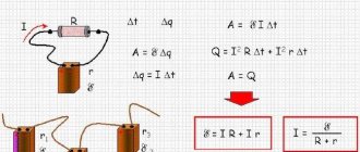
If the generator terminals are shorted to load R
(see dotted line in Fig. 1), a direct current
I = E/R
and the movement of charged particles in the generator will resume.
This (operating) mode of operation of the electric generator is quasi-stationary: the charges arriving at the electrode compensate for their departure into the external circuit. In this case, the number of charges on the electrodes (and, consequently, the potential difference) remains unchanged. Over time, the values of E
,
E
i , the dynamic equality
Fi = -F*
, and the charged particles in the volume of the generator move uniformly (“by inertia”). We emphasize that this operating mode of the generator, like the idle mode (with the external circuit open), is stationary.
In a real generator, internal resistance r* > 0
.
In operating mode, the movement of charged particles in the generator remains uniform, but external forces slightly exceed electrostatic forces - by the magnitude of the resistance forces to the movement of particles inside the generator. In this case, the potential difference on the external circuit (voltage at the generator terminals) turns out to be less than its EMF by the value Ir*
- the voltage drop inside the generator.
It should be noted, however, that the “internal resistance” r*
the
same sense as external resistance
R. The fact is that the “voltage drop” inside the generator is the energy loss of the source of external forces. It is only numerically equal to the specific (per unit of electric charge) dissipative losses of “external” energy. However, since the forces acting on a charged particle do not affect its electrical charge, heat loss does not depend on the charge of the particle. Resistance r*
is just an effective value that characterizes the internal energy losses of a source of external forces.
To show that the current inside the generator (“extraneous” current) and the current in the external circuit (potential current) are of a different nature, we compared the effective resistance of the current source r*
with the internal resistance of the same source
r
when reverse (potential) current flows through it.
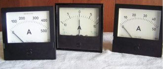
In Fig. Figure 2 shows a schematic diagram of these measurements. Voltage drop U
on the tested power source was measured with a high-resistance voltmeter
V
, and the current in the circuit was measured with a milliammeter
mA
.
The resistance store R
.
In position I of switch P
forward current from the power source was measured.
Based on the instrument readings, the effective source resistance r* = U/I
.
Then, in position II of the switch, the EMF
E1 > E
of
the source .
The reverse current I1
, from the value of which and the voltage drop
U1
at the source the true (“electrical”) resistance of the source
r
. The emf of the source was measured immediately before and after this measurement and was taken into account in the calculations.
The measurements were carried out using 1.5-volt flashlight batteries. In Fig. Figure 3 shows the results of measurements of the effective “direct” resistance r*
(dotted curve) and true “reverse”
r
(contour curve) internal resistance for three batteries of different manufacturers.
We will leave the study of the stability of the internal resistance of sources, the form of these dependencies and other questions to physical chemists (electrochemists). But the experimental results presented convincingly show that the nature of the forward (“third-party”) and reverse (“potential”) currents in electrochemical generators is different.