REPAIR OF COMPUTER POWER SUPPLY SUPPLY
In this article, I will talk a little about the basics of repairing computer, switching power supplies of the ATX standard.
This is one of my first articles, I wrote it about 5 years ago, so I ask you not to judge strictly. Precautionary measures.
Repairing switching power supplies is a rather dangerous task, especially if the fault concerns the hot part of the power supply. Therefore, we do everything thoughtfully and carefully, without haste, in compliance with safety precautions.
Power capacitors can hold a charge for a long time, so do not touch them with bare hands immediately after turning off the power. Under no circumstances should you touch the board or heatsinks while the power supply is connected to the network.
In order to avoid fireworks and preserve still living elements, you should solder a 100-watt light bulb instead of a fuse. If, when the power supply is turned on, the lamp flashes and goes out, everything is fine, but if, when turned on, the lamp lights up and does not go out, there is a short circuit somewhere.
The power supply should be checked after repairs are made away from flammable materials.
Soldering iron, solder, flux. A soldering station with power adjustment or a pair of soldering irons of different power is recommended. A powerful soldering iron is needed for soldering transistors and diode assemblies that are located on radiators, as well as transformers and chokes. Various small things are soldered with a soldering iron of lower power. Solder suction and/or braiding. Serve to remove solder. Screwdriver Side cutters. Used to remove plastic clamps that hold wires together. Multimeter Tweezers 100W light bulb Purified gasoline or alcohol. Used to clean the board from traces of soldering. BP device.
A little about what we will see when we open the power supply.
Internal image of an ATX system power supply
A – diode bridge, used to convert alternating current to direct current
B – power capacitors, used to smooth the input voltage
Between B and C there is a radiator on which the power switches are located
C – pulse transformer, serves to generate the required voltage ratings, as well as for galvanic isolation
between C and D – radiator on which rectifier diodes of output voltages are located
D – group stabilization choke (GS), used to smooth out noise at the output
E – output, filtering, capacitors, used to smooth out noise at the output
Pinout of the 24 pin connector and voltage measurement.
We will need knowledge of the contacts on the ATX connector to diagnose the power supply. Before starting repairs, you should check the voltage of the standby power supply; in the figure, this contact is marked in blue + 5V SB, usually this is a purple wire. If the duty station is in order, then you should check the presence of the POWER GOOD signal (+5V), in the figure this contact is marked in gray, PW-OK. Power good appears only after the power supply is turned on. To start the power supply, we close the green and black wires, as in the picture. If PG is present, then most likely the power supply has already started and the remaining voltages should be checked. Please note that output voltages will vary depending on the load. So, if you see 13 volts on the yellow wire, do not worry, it is likely that under load they will stabilize to the standard 12 volts.
If you have a problem in the hot part and need to measure voltages there, then all measurements must be carried out from the common ground, this is the minus of the diode bridge or power capacitors.
If the power supply is dusty, clean it. We check whether the fan is spinning; if it is, then this is most likely the reason for the failure of the power supply. In this case, you should look at diode assemblies and DGS. They are most prone to failure due to overheating.
Next, we inspect the power supply unit for burnt elements, PCB darkened by temperature, swollen capacitors, charred DGS insulation, broken tracks and wires.
Before opening the power supply, you can try to turn on the power supply to be sure of the diagnosis. A correct diagnosis is half the treatment.
The power supply does not start, there is no standby voltage. The power supply does not start, but the standby voltage is present. No PG signal. The power supply goes into defense, the power supply works, but it stinks. The output voltages are too high or low . Fuse.
If you find that a fuse has blown, do not rush to change it and turn on the power supply. In 90% of cases, a blown fuse is not the cause of the malfunction, but its consequence. In this case, first of all, you need to check the high-voltage part of the power supply, namely the diode bridge, power transistors and their wiring.
The task of the varistor is to protect the power supply from impulse noise. When a high-voltage pulse occurs, the resistance of the varistor sharply decreases to fractions of an Ohm and shunts the load, protecting it and dissipating the absorbed energy in the form of heat. When there is an overvoltage in the network, the varistor sharply reduces its resistance, and the increased current through it burns out the fuse. The remaining elements of the power supply remain intact.
A varistor fails due to voltage surges caused, for example, by a thunderstorm. Varistors also fail if you mistakenly switched the power supply to 110V operating mode. A failed varistor is usually not difficult to identify. It usually turns black and cracks, and soot appears on the surrounding elements. The fuse usually blows along with the varistor. The fuse can be replaced only after replacing the varistor and checking the remaining elements of the primary circuit.
Diode bridge
A diode bridge is a diode assembly or 4 diodes standing next to each other. You can check the diode bridge without desoldering by ringing each diode in the forward and reverse directions. In the forward direction, the current drop should be about 500mA, and in the reverse direction it should sound like a break.
Diode assemblies are measured as follows. We place the negative probe of the multimeter on the leg of the assembly with o, and call the positive probe in the directions indicated in the picture.
Capacitors
Failed capacitors can be easily identified by convex caps or leaked electrolyte. Capacitors are replaced with similar ones. Replacement with capacitors slightly larger in capacity and voltage is allowed. If the capacitors in the standby power supply circuit fail, the power supply will turn on the nth time or refuse to turn on at all. A power supply with failed output filter capacitors will turn off under load or completely refuse to turn on and will go into protection.
Sometimes, dried out, degraded capacitors fail without any visible damage. In this case, you should first remove the capacitors and check their capacitance and internal resistance. If there is nothing to check the capacitance, we replace all capacitors with ones that are known to work.
Source
Theory
The standby power supply powers the system controller while all other TV units are turned off. This is necessary so that the device can respond to the power button, of course, if it is not a big red button on the wall, but a small button on the remote control. In today's TVs, there is no separate standby mode unit, the power supply is simply capable of operating at low loads, and modules like sweep or ULF are turned off by separate transistor power switches or they simply stop receiving a control signal, which sharply reduces their appetite and heat generation.Why such a scheme is good is clear - it requires fewer parts. The worse is not so obvious, but you can also guess: the power supply is always connected to the network. You are not at home, there is lightning outside the window, a hurricane, the wires are torn, there is 380 volts in the outlet - the power supply is screwed. Maybe not everything, but the input electrolytic capacitor will certainly die. It depends on your luck. The fuse, of course, will burn out, but it will not prevent the power supply controller or power transistor from burning out either. If your TV does not work around the clock, a separate standby unit can greatly save your budget in case of poor wiring or frequent thunderstorms.
In addition, the standby power supply does not require much power, so it can be made using an ordinary small transformer. And this is a very valuable thing. Because it's heavy and durable. In different senses of the word. In particular, in terms of heat dissipation and the ability of the core to saturate. This means that it will well suppress various excess voltages of average duration - from a tenth of a second to tens of seconds. It will simply transfer excess energy that could not fit in the magnetic circuit into heat. Of which a lot fits in the copper winding and steel core.
Well, in this design, the standby power supply is made separate for two reasons: 1) the standard module does not like to work without a load (and the system controller is not a load for it); 2) preheating of the kinescope occurs with the scan turned off, the scan is the main load of the power supply unit, then see point 1.
The standby mode block is located on a separate board, which also includes power relays. The board is separate for two reasons: 1) the parts are heavy and I didn’t want to hang them on a large thin PCB; 2) the details are not unified - i.e. for each copy, those that God will send were placed. Accordingly, the board layout was different each time, and the rectifier circuit sometimes changed (bridge or multiplier).
A circuit with a conventional rectifier was used for transformers that can deliver 12-16 V under load (the heat in the second preheating stage is about 500-600 mA). A voltage multiplier circuit was used for a transformer with a winding that produced about 7 V.
The relays were different. RES-22, for example, with contacts connected in parallel in pairs, successfully controls the heat. The requirements for it are simple and clear - good insulation. When the glow is in operating mode, the potential between it and the preheating circuits can reach a hundred or two volts. The permissible current is not very large - about an ampere. Moreover, there is no pulse current (when turned on) - the contacts close while de-energized. Only when the TV is turned off, the relay can open the contacts before the scanning unit stops.
As for the power supply relay, it’s more complicated. In the closed state, the current flowing through the contacts is not large - 500 mA is the maximum. Average. The insulation requirements are simpler - only the insulation between the winding and the contacts is important - but it is usually very decent anyway. Something worse is the short circuit current. The load includes a switching power supply with large capacitors. The initial charge pulse is partly limited by a 5 ohm resistor, which is located on the standard filter board, but still - even 310 V / 5 ohm = 62 A. Even if it's not for long. In the first copy, I used a starter from Soviet TVs, it seems it was called KUTS-1. In the later ones, at first there were RP21-UHL4 relays (with a slightly weakened armature spring), then they ran out and I switched to imports: TRIH-12VDC-SB-1CH. An attempt to use RES-10 in this circuit killed it after about 20 turns on - the contacts were sintered (once upon a time there was a different experience - RES-22 included an MP-3, but without a resistor in the filter board. The contacts were sintered regularly, once a month . Then a resistor was added, but it was an MLT-2. It burned out regardless of the resistance (2..10 ohms) once every three months. It did not darken smoothly, but in a thin spiral strip. Two parallel MLT-2s seemed to solve the problem. Pulse mode , understand…).
There are now such interesting things as optothyristors, designed for currents of up to tens of amperes... Maybe this is an option? But the ones I saw cost almost as much as a relay... I didn’t want to take any risks. But someday I'll try them too.
Using Thermistors to Limit Inrush Current in Power Supplies
Often in various power supplies the task arises of limiting the starting current surge when turned on. The reasons may be different - rapid wear of relay contacts or switches, reduced service life of filter capacitors, etc. I recently had a similar problem. I use a good server power supply in my computer, but due to the unsuccessful implementation of the standby section, it overheats severely when the main power is turned off. Because of this problem, I had to repair the standby board twice already and change some of the electrolytes located next to it. The solution was simple - turn off the power supply from the outlet. But it had a number of disadvantages - when turned on, there was a strong surge of current through the high-voltage capacitor, which could damage it, in addition, after 2 weeks the power plug of the unit began to burn out. It was decided to make an inrush current limiter. In parallel with this task, I had a similar task for powerful audio amplifiers. The problems in amplifiers are the same - burning of switch contacts, current surge through the bridge diodes and filter electrolytes. You can find quite a lot of surge current limiter circuits on the Internet. But for a specific task, they may have a number of disadvantages - the need to recalculate circuit elements for the required current; for powerful consumers - selection of power elements that provide the necessary parameters for the calculated allocated power. In addition, sometimes it is necessary to provide a minimum starting current for the connected device, which increases the complexity of such a circuit. To solve this problem, there is a simple and reliable solution - thermistors.
Fig.1 Thermistor
A thermistor is a semiconductor resistor whose resistance changes sharply when heated. For our purposes, we need thermistors with a negative temperature coefficient - NTC thermistors. When current flows through the NTC thermistor, it heats up and its resistance drops.
Fig.2 TKS thermistor
We are interested in the following thermistor parameters:
Resistance at 25˚C
Maximum steady current
Both parameters are in the documentation for specific thermistors. Using the first parameter, we can determine the minimum current that will pass through the load resistance when connecting it through a thermistor. The second parameter is determined by the maximum power dissipation of the thermistor and the load power must be such that the average current through the thermistor does not exceed this value. For reliable operation of the thermistor, you need to take the value of this current less than 20 percent of the parameter specified in the documentation. It would seem that it would be easier to select the right thermistor and assemble the device. But you need to consider some points:
The energy of a charged capacitor is determined by the formula:
E = (C*Vpeak²)/2
where E is the energy in joules, C is the capacitance of the filter capacitor, Vpeak is the maximum voltage to which the filter capacitor will be charged (for our networks you can take the value 250V*√2 = 353V).
If the documentation indicates the maximum pulse power, then based on this parameter you can select a thermistor. But, as a rule, this parameter is not specified. Then the maximum capacity that can be safely charged with a thermistor can be estimated from the already calculated tables for thermistors of standard series.
I took a table with the parameters of NTC thermistors from Joyin. The table shows:
You can see how the test is carried out here on page seven.
A few words about the Cmax - the documentation shows that in the test circuit the capacitor is discharged through a thermistor and a limiting resistor, at which additional energy is released. Therefore, the maximum safe capacity that a thermistor can charge without such resistance will be less. I searched for information in foreign thematic forums and looked at typical circuits with limiters in the form of thermistors, for which data is given. Based on this information, you can take the coefficient for Cmax in a real scheme of 0.65, by which you multiply the data from the table.
Source
Powerful from the weak. We provide additional nutrition
- Introduction
- Formulation of the problem
- Modification principle
- Disassembling the power supply
- Disabling stress analysis
- Replacing a quarter bridge with a bridge
- Solder the excess
- Improvement of 12 V stabilization
- Increasing operating current
- Tests
- Conclusion
Again an upgrade, again a problem with the power supply.
Like last time, there is not enough power. It would seem like nothing, you can buy a new one. But such a block costs a lot of money. As always, they all go to more “important” parts - processor, video card, memory... Oh, how I don’t want to spend money. But there is nothing to do, you have to buy a new power supply. And what remains is an old, useless, completely serviceable block. Sometimes even several from previous upgrades. But the only thing missing is the power of the 12 V lines! Everything else is in abundance. Why not combine several blocks into one more powerful one? At the beginning of the 2000s this is what they did. It’s easy to ensure synchronous switching on of two blocks - just connect their “ground” wires and the PS_ON (green) contacts of the 20-pin connectors. Drives and hard drives were hung on one block, and everything else on the other. It helped then. But now the main energy consumption is shared between the video card and the processor. And these are 12 volt lines.
Now, if you use two old units and load only 12-volt lines on them, a voltage imbalance will occur and the stability of these same voltages will be disrupted. This is all due to the fact that in old units not each voltage is stabilized separately, but the average value between 5 and 12 V. Voltage imbalance occurs due to uneven load distribution across the +12 V and +5 V buses. Moreover, with a predominant consumption of 12 V it just goes down, and 5 V goes up. Even if this phenomenon did not occur, the old unit supplies at best a third of the power via the 12 V line. In modern conditions this is not enough. And the efficiency of such a system will be low.
This can be avoided by modifying the second power supply so that it stabilizes only the 12 V line and delivers all its power to it. In 2004, I wrote an article on this topic. It described a way to remove only the voltage imbalance. This is no longer enough. Now everything looks different.
Several years ago, additional power supplies for video cards appeared on sale: FSP VGA Power,
. Correct solution. The power of the old unit is almost always more than enough to power the motherboard and processor, but for the video card... Not anymore.
A regular computer rarely requires a power supply more powerful than 450 W, but everything changes when it comes to high-performance gaming systems. A modern top-end video card consumes a fair amount. And there are video cards with two GPUs. And they can also be combined into SLI or CrossFire... Here it’s nice to have two independent +12 V power lines with a current of 30 A, which allows you to organize SLI or CrossFire without loading the main power supply of the system.
The use of several blocks is possible because manufacturers began to equip motherboards with processor power connectors that are not electrically connected to the 20-pin ATX connector. Additional power connectors also exist on video cards. They can also be powered from a separate source. Unfortunately, such devices are not widely used. Why? I think it's about the price. It’s easier to add a little more and buy a full-fledged unit.
announcements and advertising
RTX 3070 Ti Aorus at a non-Ti price
RTX 3080 for 288 tr in Citylink
RTX 3090 MSI for 539 TR
Earn money by participating in the content of our site
Another 3080 is even cheaper - see the price
Cool 3060 Ti Gigabyte Aorus fell in price 2 times
What if you make such a power supply yourself? From the old, unnecessary. It will cost much less.
So, the task is to take the old power supply and force it to deliver all the power it is capable of through the 12 V line. The remaining lines are dismantled. And so that this block turns on synchronously with the second block that powers all the other hardware. Provide the ability to expand the system. If one thing is not enough, add one more.
For remodeling, it is advisable to take a power supply with a power of 350 W or more. Why? Ohm's law. With a power of 350 W and a voltage of 12 V, the current will be 29.2 A. The required minimum.
There are two types of blocks. Old ones, with the main load on the 5 V line, and new ones with the main load on the 12 V line. In this article, we will look at a unit with a powerful 5 volt line. Let's take the PowerMan IW-P430J2-0 power supply as a test subject.
It is made on the SG6105 PWM chip. Exactly the same modification is possible if the block contains its analogue IW1688. Following the principle set out in the article, you can remake the power supply with a different PWM.
WARNING:
Before taking on this work, I warn you that during the reworking process you can easily get exposed to life-threatening voltage and also burn the power supply. You must have the appropriate qualifications and do all work at your own peril and risk. The author is not responsible for this.
To work you will need some tools and parts:
- Soldering iron, preferably two. One is normal, the other is with a desoldering pump. Or a separate tool like this.
- Multimeter. Tweezers. Side cutters.
- 12 volt spot light bulb with socket. For check.
- Fixed resistors with a nominal value of 47 kOhm, 33 kOhm, 6.2 kOhm, 3.3 kOhm, 1.5 kOhm, 100 Ohm. But it’s better to have several resistors on hand that are close in value to each one on the list.
- Capacitors, one or two with a capacity of 2200 - 4000 mF for a voltage of 16-25 V.
- Diode assemblies 30 - 40 A for voltage from 40 V. Two - three.
- Wires, connectors for connecting a video card.
We upgrade the power supply so that it delivers all the power it is capable of only to the 12 V line. But the PWM chip of the power supply analyzes all the voltages produced by the unit, and if they deviate from the nominal value, it turns off the unit. Let's start by turning off monitoring of all voltages except 12 V. Solder off all unnecessary parts. We force the block to work on only one line. And honestly give out everything that he is capable of in this ONE 12 V line.
The principle of disabling monitoring is simple. We need to trick SQ6105. The power supply has a “standby power supply”. This is an independent 5 V source. From it, power is supplied to the SQ6105 until the entire unit is turned on.
For example, how to disable 5V monitoring? Apply a voltage of 5 V to the SQ6105 pin, which is responsible for this monitoring. And take it from this very “duty room”. Monitoring +3.3 V? Take 5 V from the “duty room” and, using a resistor divider, supply the required 3.3 V to the SQ6105! The 12 volt line remains. Now step by step and in detail.
We take out the board. Solder the wire and plug to it. For ease of inclusion. For a short time and with a light load, the unit can be turned on without a fan. We connect a load to the output of the power supply - a 12 V light bulb. The PS-ON wire to ground means - we short-circuit the green and black wires of the 20-pin connector with a paper clip. The light is on. The block is working.
We disconnect the power supply from the 220 V network. (You need to unplug the power cord from the outlet!) This is important. Otherwise, you will receive an electric shock and possibly die. Electricity is no joke. On the board we find the SQ6105 chip, turn the board over and look for the place where it is soldered. We look at the pin numbering of SQ6105 and check it with.
Let's get to work.
We turn off the analysis of SQ6105 plus 5 V - we cut the track coming from leg 3, SQ6105 (V5 voltage input + 5V,
),
and we connect pin 3 itself by soldering to pin 20 of the SQ6105 with a jumper ( ).
Thus, we disconnect the SQ6105 from the power supply circuit and replace the 5-volt output monitoring with five “standby” volts. Now, even if the power supply does not supply 5 V to the load, the SQ6105 considers that everything is normal and the protection does not work. Ready.
We turn on the power supply to the network to check, the light should be on. If the light does not light up, check the voltage output from the standby power supply. If more than 5 V, then the jumper should be replaced with a resistor of 100-200 Ohms.
Disconnect the power supply from the 220 V network. Remove the definition of SQ6105 plus 3.3 V - cut the track near pin 2
and solder two resistors, 3.3 kOhm from pin 2 to the case, 1.5 kOhm from pin 2 to pin 20 ().
We turn on the power supply to the network; if it doesn’t turn on, you need to select resistors more accurately to get +3.3 V at pin 2. You can use a trimming resistor. After each alteration, it is better to check the unit for operability, then if something happens, you won’t have to rack your brains for a long time over the cause.
We disconnect the power supply from the 220 V network. We remove the definition of SQ6105 minus -5 V and - 12 V - unsolder R44 or whatever is there (near pin 6),
and pin 6 itself is connected to the housing through a 33 kOhm resistor ().
We turn on the power supply to the network; if it does not turn on, we need to select a resistor more accurately. In this case, the unit worked with a resistor value of 31 Ohms. The value is obtained by connecting resistors in series. The voltage on leg 6 of the microcircuit must be no more than 2.1 V. Otherwise, the unit will not turn on. By decreasing the resistor value, we reduce the voltage. You can measure the voltage on leg 6 by simply turning on the unit in the network, without turning on PS ON.
Let's look at the power supply diagram again. In my power supply, the most powerful line is 5 V. This is indicated by the largest cross-section of the transformer output wire of all windings. Three wires in the group stabilization choke versus one 12 V line. And also a tag on the power supply. According to it, the unit can produce 32 A of current. And the 12 volt line is weak.
But you need just 12. What to do? We take a 5 volt line and instead of a full-wave rectifier with a midpoint on a diode assembly we assemble
. And let's turn off the middle point. Thus, the voltage at the bridge output will be twice as high as it was at the output
. To do this, using a soldering iron with a desoldering pump, we solder the radiator with diode assemblies. Let's see. On the 5 V rectification there is one assembly for 40 A. At 12 volts 20 A. We immediately unscrew it. Turn the radiator over.
To rectify 5 volts, there is one 40 A assembly. But it is possible to install another one, on the other side of the radiator. This is because the printed circuit boards are the same for the entire line of these units from 300 to 450 W. Let's put another one. At the same time, remove the first one, add thermal paste KPT-8. Don't forget about the insulating gaskets. After assembly, we check with a multimeter whether the assembly is ringing on the body. This shouldn't happen.
To rectify 3.3 volts there is a 40 A assembly. We rearrange it horizontally. We unscrew the assembly responsible for rectifying 12 volts and replace it with a 40-amp one, which we also place horizontally.
I install assemblies with such a huge current reserve due to the fact that I use them from old power supplies. But they were not previously highly reliable. And two assemblies heat up less than one. Again, reliability is higher. In principle, it was possible to put one 40 A in the forward direction, and the other two 20 A each. But I love the margin and reliability.
Now we cut out a strip of copper and use it to connect the extreme terminals of the horizontally fixed diode assemblies by soldering. The copper in the photo is white because it is silver plated (thanks to the USSR). There is no need to worry about short circuits, since both the radiator and this strip are connected to a common wire. We place the radiator on the table, connect the middle terminal of the assembly to the left terminal of the other assembly. As in the photo below.
We turn the radiator over and connect the middle terminal of the assembly to the left terminal of the second assembly.
ATTENTION.
The middle pins are soldered to different anodes of the assemblies. It turns out that the terminals of the assemblies are each connected to their own terminal of the transformer via the 5 V line.
The connection must correspond to the diagram (see).
We solder the radiator and assemblies into place. Now we turn off the middle point of the transformer. We simply bite off the wire going from the transformer to the board. We take a bite near the transformer. And we solder the wire to the copper plate connecting the anodes of the diode assemblies on the radiator. The length of the wire was a little short, so I extended it with a wire with a cross-section of 4 mm square.
Pinout of the main PSU connector
To carry out repairs, we will also need to know the pinout of the main power connector, it is shown below.
PSU plugs: A – old style (20pin), B – new (24pin)
To start the power supply, you need to connect the green wire (PS_ON#) to any black zero wire. This can be done using a regular jumper. Note that some devices may have color markings that differ from the standard ones; as a rule, unknown manufacturers from the Middle Kingdom are guilty of this.
PSU load
It is necessary to warn that switching on switching power supplies without load significantly reduces their service life and can even cause failure. Therefore, we recommend assembling a simple load block; its diagram is shown in the figure.
Load block diagram
It is advisable to assemble the circuit using resistors of the PEV-10 brand, their ratings are: R1 - 10 Ohms, R2 and R3 - 3.3 Ohms, R4 and R5 - 1.2 Ohms. Cooling for the resistances can be made from aluminum channel.
It is not advisable to connect a motherboard or, as some “craftsmen” advise, a HDD and CD drive as a load during diagnostics, since a faulty power supply can damage them.
Method 1. Checking the power supply for functionality
Now let's check if the power supply is working. To do this, we will use a paper clip as a jumper.
- Disconnect the computer from the 220V network.
- Disconnect all power supply wires connected to the motherboard, hard drive, etc.
- We connect the green wire with a paper clip to any black wire on the 24 pin connector, as shown in the photo below.
We close the green and black wires in the connector.
We connect the power cable; if the fan in the power supply does not spin, it means the power supply is faulty. To be sure of this, take a Phillips screwdriver, unscrew the 4 bolts and remove the cover on the block.
Check the rotation of the fan - it should spin easily. If it turns with difficulty, then it needs to be lubricated.
Checking the fan in the power supply
Clean the power supply from dust and inspect for swollen capacitors. Swollen capacitors need to be replaced.
Swollen capacitors in the power supply
If you have any problems with your computer, you can contact me for advice - join the VK group.
I will help you solve a problem with your PC or laptop.
Join the VK group - ruslankomp If the fan in the power supply spins when the cable is connected, then the power supply is working. But to check whether it is working properly, you need to measure the indicators with a multimeter.
Test method (instructions)
After the power supply is removed from the system unit and disassembled, first of all, it is necessary to inspect it to detect damaged elements (darkening, changed color, loss of integrity). Note that in most cases, replacing the burnt part will not solve the problem; you will need to check the piping.
Visual inspection allows you to detect “burnt out” radioelements
If none are found, proceed to the following algorithm of actions:
If a faulty transistor is found, then before soldering in a new one, it is necessary to test its entire wiring, consisting of diodes, low-resistance resistances and electrolytic capacitors. We recommend replacing the latter with new ones that have a larger capacity. Good results are obtained by shunting electrolytes using 0.1 μF ceramic capacitors;
It is not uncommon for an apparently normal capacitor to turn out to be unusable when tested. Therefore, it is better to test them with a multimeter that has a capacitance measurement function, or use a special device for this.
Video: correct repair of an ATX power supply. https://www.youtube.com/watch?v=AAMU8R36qyE
Note that non-working output capacitors are the most common fault in computer power supplies. In 80% of cases, after replacing them, the performance of the power supply is restored;
Where to start, how to find the right scheme
The best repair option is if there is a circuit diagram for a specific power supply. In reality, everything is somewhat more complicated. Manufacturers do not include circuit diagrams in the documentation for power supplies. You have to look for them on the Internet. The problem is that even well-known manufacturers are not enthusiastic about showing off their developments, and small companies from Southeast Asia do not have their own websites at all. We have to collect from the entire network what enthusiasts have found and posted. And if it is relatively easy to find a circuit for computer power supplies, then for pulse generators intended, for example, to power LED strips, the situation is more complicated.
SMPS SKS-320.
Thus, for the SKS-320 power supply, when requesting a diagram, a well-known search engine produces only one adequate picture (obviously drawn by a volunteer from China). Using this device as an example, the troubleshooting algorithm will be described below.
Schematic diagram of the UPS SKS-320.
For other sources, the diagram may not be found at all. In this case, the best solution is to copy the circuit from the board yourself. This requires certain qualifications - you must, at a minimum, know what electronic components look like, and also have an approximate idea of the expected result. To do this, you need to know what circuit design the power supplies are made of. To make your work easier, you can mark the power paths on the board with a marker and number the elements (if they are not already numbered).
Another way is to find a similar circuit, which may not completely coincide with the real block, but this is better than nothing.
About the role of varistors/thermistors in power supplies
High-quality power supplies ensure long-term reliable and trouble-free operation of computing equipment and other equipment.
Since mining uses powerful switching power supplies that power expensive equipment, their failure entails very unpleasant consequences.
In this regard, it is worth understanding some of the features of their operation, which will help to avoid breakdowns caused by a lack of understanding of the processes occurring inside switching power supplies.
Transient processes in electronic equipment and computer technology
During the operation of any electrical devices, at the moment of switching, nonlinear transient processes occur, which in some cases are imperceptible, and sometimes lead to the device leaving the design mode of operation, which is accompanied by an increased load on its elements and can lead to their failure.
Transient processes always occur at the moment of switching circuits with a load that is inductive and/or capacitive in nature. In most cases, they are harmful to the operation of the device, so hardware designers usually take measures to reduce them to a minimum.
Since any section of the circuit has LC parameters to one degree or another, nonlinear processes always occur in any electronics. Powerful power supplies used for mining contain capacitors and large capacitance/inductance coils, so transients in them can be very significant.
A short burst of AC voltage significantly exceeding the normal value:
When a high-power power supply is switched on, current pulses of enormous magnitude flow through its circuits. Voltage surges caused by transients can be many times higher than the rated voltage flowing in the network.
Voltage spikes appearing on a sinusoidal alternating voltage graph due to transients:
To combat voltage surges when power supplies are turned on, special protective elements are installed in them. They usually cope with their role, but sometimes, in emergency situations, they fail to cope with their tasks. In order to prevent their occurrence (or at least reduce them to a minimum), you need to know the principles of operation, the purpose and composition of the protective elements at the input of the switching power supply.
Application of VRM
The board has a connector for connecting power; today the standard provides for the installation of at least two connectors - a 24-pin ATX and a 4-pin ATX12V for an additional 12V line. Sometimes motherboard manufacturers install 8-pin EPS12V instead of ATX12V; two 12V lines can be connected through it. The power supplied by the power supply is converted, stabilized and filtered using power field-effect transistors (MOSFETs), chokes and capacitors that make up the VRM (Voltage Regulation Module). The processor and chipset are powered by one VRM, and the memory modules are powered most often by another. Additionally, to stabilize the power supplied through PCI Express connectors, standard Molex connectors are sometimes installed.
VRM is designed to allow existing motherboards to support multiple types of processors, as well as those coming in the future. After all, each processor has its own supply voltage. When installing the processor into the motherboard, using the corresponding VID pins (4 or 6 pieces), it determines the model of the installed processor and supplies the corresponding supply voltage to its crystal (core). In fact, the combination of 0 and 1 on the VID pins specifies a 4 or 6-bit code by which the VRM “learns” about the processor model.
For example, let's look at the power supply for processor cores of the Intel Core 2 Extreme model (Conroe, technical process, 65 nm, frequency 2.93 GHz, 4 MB L2).
For this processor, the VID value is in the range of 0.85–1.36525 V, the maximum current for the top model E6800 can reach 90 A, for the rest, represented by the models E6300, E6400, E6600, E6700, - 75 A. VRM for Intel processors Core 2 Duo must meet specification 11.0.
There are two types of regulators: linear and pulse . The linear voltage regulator used in older boards was a microcircuit that lowers the voltage by dissipating excess voltage as heat. As the required voltage decreased, the thermal power dissipated by such regulators increased, so they were equipped with massive heatsinks, which made them easy to find on the motherboard. When installing a processor that consumes a lot of power into the motherboard, the regulator (and with it the motherboard) could fail due to overheating. Therefore, modern motherboards use a switching regulator containing a low-pass smoothing filter, to which a sequence of short pulses of full voltage is applied.
The switching stabilizer contains a reactive-inductive LC filter, to which the full supply voltage is supplied in short pulses, and due to the inertia of the capacitance and inductance, it is leveled to the required value, and practically no useless energy losses occur. Voltage stability is maintained by controlling the frequency and width of the pulses ( pulse width modulation, PWM ). In pulse-width modulation, a periodic sequence of rectangular pulses is used as a carrier oscillation, and the information parameter associated with the discrete modulating signal is the duration of these pulses. A periodic sequence of rectangular pulses of the same duration has a constant component, inversely proportional to the duty cycle of the pulses, that is, directly proportional to their duration. By passing pulses through a low-pass filter with a cutoff frequency significantly lower than the pulse repetition rate, this constant component can be easily isolated, obtaining a stable constant voltage.
The use of switching stabilizers can significantly reduce heat generation, but creates an additional source of interference that can affect the operation of video and audio adapters.
Due to the inertia of the filter, the pulses are smoothed into the required constant voltage. The efficiency of such a converter is very high, so there is almost no parasitic heating. You can recognize the switching voltage regulator on the board by the inductors. All new boards use a multi-channel (multi-phase) voltage converter, which lowers the supply voltage to the required 0.8-1.7 V on the processor core (depending on the model).
Three-channel VRM on K8NS board (Socket-939)
Thus, a VRM is essentially a PWM regulator on a chip with MOSFET converters and a filter . Typically, the voltage on the motherboard is higher than on the processor core.
Traditionally, the main voltage regulators are located around the processor socket. Considering the high values of consumed currents, they are created multi-channel (multi-phase). Usually there are three or four of them, but on top boards their number can reach 8. Refusal of single-channel power supply reduces the load on the control transistors. In order to improve the temperature conditions of their operation, as well as increase reliability, power transistors are often equipped with cooling means (radiators).
In addition to the multi-channel VRM, the video adapter circuits and RAM modules are equipped with individual power supply systems. They provide the required voltage and current levels, and also reduce the mutual influence transmitted along the power buses.
A large number of fans concentrated in a small volume creates a relatively high level of acoustic noise. It can be reduced by special design of motherboards, which involves the use of solutions based on heat pipes.
An example is the Gigabyte GA-965P-DQ6 board. On it, heatsinks installed on both chipset chips are connected by several heat pipes to heatsinks installed on VRM power transistors.
This solution ensures efficient redistribution of heat flows between several radiators. As a result, the temperatures of elements operating in key modes, which are sources of uneven heating, are equalized both in space and time. Cooling of the entire structure is facilitated by the overall design, which involves the use of air flows generated by the processor and cooler fans.
Assessing the effectiveness of this solution, it should be noted that another factor that helps reduce thermal and electrical loads on VRM transistors is the implementation of a large number of power supply channels (phases). For example, in the architecture of the specified board there are twelve of them. Such a large number of channels significantly simplifies the VRM design, improves isolation along power lines, reduces electrical noise and increases the stability of computer subsystems. In addition, the described design with passive coolers, an analogue of which is actively used, by the way, in silent models of video adapters from the same manufacturer, reduces acoustic noise from the motherboard.
The design of the voltage regulator allows it to be supplied with 5 or 12 V (the output is the processor supply voltage). The system primarily uses 5V, but many components are now moving to 12V due to their power consumption. In addition, 12 V is typically used by the drive motor, while all other devices consume 5 V. The amount of voltage consumed by the VRM (5 or 12 V) depends on the motherboard used or the design of the regulator. Modern voltage regulator ICs are designed to operate from 4 to 36 V input voltages, so their configuration is entirely up to the motherboard designer.
Typically, motherboards designed for Pentium III and Athlon/Duron processors used 5-volt voltage regulators. In recent years, there has been a trend towards switching to 12V regulators. This is due to the fact that using a higher voltage allows you to significantly reduce the current load. For example, if you use the same 65-watt AMD Athlon processor with an operating frequency of 1 GHz, you can get several load levels at different voltage consumption values
When using 12 V, the current consumption is only 5.4 A, or, taking into account 75% efficiency of the voltage regulator, 7.2 A. Thus, modifying the motherboard VRM circuit to use 12 V seems quite simple. Unfortunately, the standard ATX 2.03 power supply contains only one +12 V pin in the main power connector. The additional connector does not contain +12 V pins at all, so it is of little use. Applying 8 A or more current to the system board at +12 V through a standard wire may damage the connector.
To improve the power supply of motherboards, Intel created a new specification for ATX12V power supplies. The result of this was a new power connector designed to supply additional +12V voltage to the motherboard.
ASUS P5B-E Plus board , based on the Intel P965 Express chipset, uses a 4-channel VRM, which means it is more suitable for reliable support of powerful (or highly overclocked) processors. The design provides for cooling of half of the key transistors, but this model does not have a radiator installed. The power supply connector on the VRM is made 8-pin to halve the current passing through the +12 V lines. However, if your power supply does not have such a connector, you can connect the board via a 4-pin connector.
The processor and chipset are powered by one VRM, while the memory modules and video adapter are powered by others, most often. This ensures the required levels of voltages and currents, the absence of power drawdowns, and also reduces the mutual influence transmitted along the power buses.
Why are protective circuits needed at the input of switching power supplies?
High-quality switching power supplies usually install input circuits that solve a number of problems, including:
To protect the input circuits of the power supply from voltage and current surges, varistors and thermistors, as well as fuses, varistors, and surge arresters are used.
MOV varistor and thermistors with positive and negative resistance coefficient:
How is protection provided against surges in voltage and current at the input of the power supply?
Varistors and arresters are usually responsible for protection against voltage surges at the input of a pulse power supply in operating mode. To protect against current surges, fuses and thermistors are used at the input.
The simplest circuit for connecting a protective varistor in a power supply:
Scheme for connecting protective elements at the input of a pulsed current source using varistors and arresters:
Repairing a computer power supply: diagrams for instructions
If your computer's power supply fails, do not rush to get upset; as practice shows, in most cases repairs can be done on your own. Before moving directly to the methodology, we will consider the block diagram of the power supply and provide a list of possible faults; this will significantly simplify the task.
Structural scheme
The figure shows an image of a block diagram typical for switching power supply system units.
How does a varistor work?
A varistor is a resistor whose resistance changes depending on the applied voltage. Under normal conditions, it is very large (megaOhms) and does not have much effect on the operation of the electrical circuit when connected in parallel.
Volt-ampere characteristic of the varistor:
With a significant increase in voltage across the varistor, the resistance drops, which leads to the absorption of the surge energy and its release in the form of heat.
Varistors are needed to protect electronic devices from high voltage surges due to the fact that their resistance drops sharply with increasing voltage applied to them:
This saves other components from failure, although sometimes it leads to burnout of the varistor itself, which saves more expensive electronic elements with its heroic behavior. Varistors are installed at the input of the power supply in front of the diode rectifier, since they additionally perform a filtering function - suppressing interference that occurs when the diode bridge is turned off.
Varistor TVR 14471 at the input of the Be Quiet Dark Power Pro power supply 1200 watts with platinum certificate:
ATX power supply, device and principle of operation. Part 1.
Since the power supply is an integral part of the PC, it will be interesting for every person involved in electronics and not only to know more about it.
The performance of the PC as a whole directly depends on the quality of the power supply. And so, I believe that we need to start with the simplest, for what purpose the power supply is intended: - generating the supply voltage for PC components: +3.3 +5 +12 Volts (additionally -12V and -5V); - galvanic isolation between 220 and the PC (so that there is no electric shock, and there are no current leaks when pairing components). A simple example of galvanic isolation is a transformer. But to power a PC, you need a lot of power, and therefore a large transformer (the computer would be very large :), and two people would have to carry it due to its considerable weight, but we avoided this :)). To build compact blocks, an increased frequency of the transformer supply current is used; as the frequency increases, the same magnetic flux in the transformer requires a smaller cross-section of the magnetic circuit and fewer turns. The creation of light and compact power supplies allows the frequency of the transformer supply voltage to be increased by 1000 times or more. The basic principle of operation of the power supply is as follows: the conversion of alternating mains voltage (50 Hz) into AC. a high-frequency voltage of a rectangular shape (if an oscilloscope could show an example), which is lowered using a transformer, then rectified and filtered. Block diagram of a pulse power supply.
1. Block Converts 220V variable to constant. The composition of such a block is: a diode bridge for rectifying alternating voltage + a filter for smoothing ripples of the rectified voltage. There should also be (in cheap power supplies they save money by not soldering them, but I immediately recommend installing them when remodeling or repairing) a network voltage filter from the ripples of the pulse generator, as well as thermistors to smooth out the current surge when turned on. In the picture, the filter is indicated by a dotted line in the diagram; we will see it in almost any power supply circuit (but not always on the board :)). 2. Block This block generates pulses of a certain frequency that feed the primary winding of the transformer. The frequency of generating pulses from various power supply manufacturers is somewhere in the range of 30-200 kHz. 3. Block The transformer has the following functions: - galvanic isolation; — reducing the voltage on the secondary windings to the required level. 4. Block This block converts the voltage received from block 3 into DC. It consists of voltage-rectifying diodes and a ripple filter. The filter consists of a choke and a group of capacitors. Often, to save money, capacitors are installed with low capacitance and chokes with low inductance.
Pulse generator in more detail.
The RF converter circuit consists of powerful transistors that operate in switch and pulse transformer mode. The power supply can be a single-cycle or push-pull converter: - single-cycle: one transistor opens and closes; - push-pull: two transistors alternately open and close. Let's look at the drawing.
Circuit elements: R1 - resistance that sets the bias on the keys. Necessary for a more stable start of the oscillation process in the converter. R2 is a resistance that limits the base current on the transistors and is necessary to protect the transistors from failure. TP1 - Transformer with three groups of windings. The first generates the output voltage. The second serves as a load for transistors. The third generates the control voltage for the transistors. When the first circuit is turned on, the transistor is slightly open, because a positive voltage is applied to the base through resistor R1. A current flows through the slightly open transistor, which flows through winding II. The current creates a magnetic field. The magnetic field creates voltage in the remaining windings. A positive voltage is created on winding III, which opens the transistor even more. The process continues until the transistor enters saturation mode. The saturation mode is characterized by the fact that when the applied control current to the transistor increases, the output current remains unchanged. Only when the magnetic field changes is voltage generated on the windings; if there are no changes on the transistor, the EMF in windings II and III will also disappear. When the voltage on winding III disappears, then the opening of the transistor will decrease, and therefore the output current of the transistor and the magnetic field will decrease, which will lead to the appearance of a voltage of the opposite polarity. Negative voltage on winding III will close the transistor even more. The process continues until the magnetic field disappears completely. When the field disappears, the negative voltage will disappear and the process will begin in a circle again. A push-pull converter works the same way, but since it has two transistors operating alternately, this application increases the efficiency of the converter and improves its performance. Mostly they use two-stroke ones, but if you need low power and dimensions, as well as simplicity, then single-stroke ones. The converters discussed above are complete devices, but their use is complicated by the variation of various parameters such as: output load, supply voltage, and temperature of the converter.
Control of keys by PWM controller (494).
The converter consists of transformer T1 and transistor VT1. The mains voltage is supplied through a mains filter (SF) to a mains rectifier (RM) diode bridge, filtered by a capacitor SF and supplied through winding W1 to the collector of transistor VT1. When a rectangular pulse is applied to the base of the transistor, it opens and current Ik flows through it, which increases. The same current flowing through the primary winding of transformer T1 leads to an increase in the magnetic flux in the transformer core and induced self-inductive emf in the secondary winding W2. As a result, a positive voltage will appear on the VD diode. By increasing the duration of the pulse based on transistor VT1, the voltage in the secondary circuit will increase, and if you decrease the duration, the voltage will decrease. By changing the pulse duration on the base of the transistor, we change the output voltage on the W1 winding of T1, and stabilize the output voltages of the power supply. We need a circuit for generating trigger pulses and controlling their duration (latitude). This circuit uses a PWM (pulse width modulation) controller. The PWM controller consists of: - a master pulse generator (which determines the operating frequency of the converter); — control circuits; — a logical circuit that controls the pulse duration; — protection schemes. This is the topic of another article. In order to stabilize the output voltages of the power supply unit, the PWM controller circuit “must know” the magnitude of the output voltages. For this, a feedback circuit (or tracking circuit) is used, made on optocoupler U1 and resistor R2. An increase in voltage in the secondary circuit of transformer T1 will lead to an increase in the intensity of the LED radiation, and therefore a decrease in the junction resistance of the phototransistor (part of the optocoupler U1). This leads to resistor R2 connected in series with the phototransistor to an increase in the voltage drop and a decrease in the voltage at pin 1 of the PWM switch. A decrease in voltage causes the logic circuit that makes up the PWM to increase the pulse duration until the voltage at pin 1 matches the specified parameters. The process is reversed when the voltage decreases. There are two implementations of feedback circuits: - “direct” in the diagram above, feedback is removed directly from the secondary rectifier; - “indirect” is removed directly from the additional winding W3 (see figure below); A change in voltage on the secondary winding will lead to a change in it on winding W3, which is transmitted through R2 to 1 pin of the PWM switch.
Below is a real power supply diagram.
1. The block rectifies and filters alternating voltage, and there is also a filter against interference created by the power supply itself. 2. Block This block generates +5VSB (standby voltage) and also powers the PWM controller. 3. Block The third block (PWM - controller 494) contains the following functions: - control of transistor switches; — stabilization of output voltages; — short circuit protection. 4. Block This block includes two transformers and two groups of transistor switches. The first transformer generates the control voltage for the output transistors. 1 group of transistors amplifies the generated signal TL494 and transmits it to the first transformer. Group 2 of transistors is loaded onto the main transformer, on which the main supply voltages are formed. 5. Block This block includes Schottky diodes to rectify the output voltage of the transformer, as well as a low-pass filter. The low-pass filter includes electrolytic capacitors of large capacities (depending on the power supply manufacturer) and chokes, as well as resistors for discharging these capacitors when the power supply is turned off.
A little about the duty room.
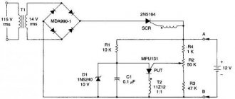
The differences between ATX standard units and AT standard power supplies are that ATX standard power supplies have a standby supply voltage source. At pin 9 (20 pin, purple wire) of the connector, a voltage of +5VSB is generated which goes to the motherboard to power the power supply control circuit. This circuit generates the “PS-ON” signal (pin 14 of the connector, green wire). In this circuit, the converter operates at a frequency determined mainly by the parameters of transformer T3 and the values of the elements in the base circuit of the key transistor Q5 - the capacitance of capacitor C28 and the resistance of the initial bias resistor R48 [1]. Positive feedback to the base of transistor Q5 comes from the auxiliary winding of transformer T2 through elements C28 and R51. The negative voltage from the same winding after the rectifier on elements D29 and C27, if it exceeds the stabilization voltage of the zener diode ZD1 (in this case 16 V), is also supplied to the base Q5, prohibiting the operation of the converter. In this way, the output voltage level is monitored. The supply voltage from the mains rectifier is supplied to the converter through the current-limiting resistor R45, which, if it fails, can be replaced with a 500 mA fuse or eliminated altogether. In the circuit in Fig. 1, resistor R56 with a nominal value of 0.5 Ohm, connected to the emitter of transistor Q5, is a current sensor; when the current of transistor Q5 exceeds the permissible value, the voltage from it through resistor R54 goes to the base of transistor Q9 of type 2SC945, opening it, and thereby prohibiting the operation of Q5 . In a similar way, additional protection is provided for Q5 and the primary winding T3. Chain R47C29 serves to protect transistor Q5 from voltage surges. KSC5027 transistors are used as the key transistor Q5 in the specified power supply model. In my previous article, the power supply was based on similar elements (duty room).
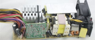
Now let’s look at the power supply unit live.
1. Elements of a network filter against interference generated by power supply units. 2. Diode bridge rectifying 220V variables. 3. Mains voltage filter capacitances. 4. Radiator for the output transistors of the converter, as well as the transistor of the duty converter. 5. Main transformer: isolation from the network and generation of all voltages. 6. Transformer for generating the control voltage of the output transistors. 7. Converter transformer that generates standby voltage. 8. Radiator for Schottky diodes. 9. PWM controller chip. 10. Output voltage filters (electrolytic capacitors). 11. Output voltage filter chokes.
I'll stop there for now. Thank you all for your attention for so long. I hope it was useful to at least someone. I look forward to comments and suggestions for additions. To be continued…
Why are thermistors used in the power supply?
A thermistor is a resistor that changes its resistance due to temperature.
Power supplies typically use Negative Temperature Coefficient (NTC) thermistors connected in series with the load. When cold, they have a resistance of 6-12 Ohms, so when the power supply is turned on, they warm up. Due to heating, the resistance of NTC thermistors drops to 0.5-1 Ohm and they no longer have a significant effect on the operation of the device.
In expensive power supplies, after a successful start of the power supply, the thermistors are turned off, the current begins to pass through the conductor with zero resistance, which ensures a cold state of the thermistor (constant readiness to turn on the power supply again), and also saves electricity, which is wasted during the operation of the power supply in normal conditions. mode.
Due to the fact that the thermistor takes on “part of the shock” at the moment of switching on, the remaining components are not affected.
The simplest circuit for connecting a protective thermistor at the input of the power supply:
Varistors provide protection for the high-voltage part of the power supply from voltage surges, and thermistors protect against high current.
Varistor VZ1 and thermistor TR101 on the diagram of the Chieftec APS-550S power supply with a power of 550W:
Monitoring of main voltages and Power Good signal
If the power supply starts (and the fan starts spinning), you should check the voltages +3.3 V, + 5 V, +12 V and the PG (Power Good) signal.
The voltage at the PG pin should be +5 V.
We remind you that these voltages must be within 5% of the tolerance range.
The Power Good signal is used to start the processor.
When the power supply is turned on, transient processes occur in it, accompanied by jumps in output voltages.
This may be accompanied by loss or corruption of data in processor registers.
If the signal at the PG pin is inactive (the voltage on it is zero), then the processor is in a reset state and does not start.
The signal at this pin usually appears 0.3 - 0.5 s after switching on. If, after switching on, the voltage there remains zero, this is a difficult case; we’ll leave it to the professionals.
If the standby voltage is below 4.5 V, the computer may not start. If it is higher (this happens), the computer will start, but it may freeze and crash.
If the voltage of the standby source is not within normal limits, this is also a difficult case, but several standard procedures for checking parts can be performed.
What can savings on varistors and thermistors in the power supply lead to?
In budget power supplies, manufacturers save on the element base and do not install varistors. To protect such power supplies, it is worth using surge protectors or UPSs containing varistors. The cost of such protection is justified by the significant reduction in possible damage that may occur in the event of a burnout of the power source powering an expensive computer.
In some cases, the surge voltage/current protection provided by varistors and thermistors does not work. This can happen if the varistor/thermistor is faulty, or if such an element is heated and is turned on based on its condition at normal temperature. A situation with slow cooling of protective varistors (thermistors) may arise if a working power supply is turned on too quickly.
If the thermistor does not have time to cool down after turning off the power supply, then at the moment the high voltage is reapplied, the protection provided by extinguishing the energy at its high resistance is not provided. This can lead to disastrous consequences.
A heated varistor does not absorb the energy of the pulse that appears at the moment of switching on due to the charging of the capacitors of electrolytic capacitors and the accumulation of energy in inductances, which usually leads to breakdown of transistors in the high-voltage part of the power supply.
Due to this, the high voltage pulse arriving at the protected device is suppressed by the varistor. If the varistor is overheated, irreversible changes may occur in it, leading to breakdown or breakage.
Example of a board for a cheap Green Vision GV-PS S400 power supply:
If the power supply crackles (whistles, beeps, rings).
The crackling (whistle) of the power supply can be caused by various reasons. Including low-quality inductive elements or capacitances. This review will tell you about a specific example of finding and eliminating such noise. The elimination method will not be entirely standard. I have this 12V 5A power supply:
Everything would be fine if it were not for its extremely unpleasant noise in the form of a crackling squeak at no or low load.
Noise terminology: crackling, squeaking, whistling, ringing, etc. I’ll leave it to people who have special acoustic education, and I’ll just try to eliminate this noise. Below there will be a demonstration of this sound.
But first you need to disassemble the power supply. It is assembled without any cracks or gaps, apparently sealed. Attempts to warm it up with a hairdryer and separate the halves led nowhere.
The next attempt was to disconnect it with brute force, since I still found several very small gaps in the halves of the case. And lo and behold, he found himself on the latches and figured it out further without any problems. The case has three latches on each long side. There are no latches on the short sides, but there are guides on one:
Let me remind you right away that before any further manipulations, be sure to discharge the large high-voltage capacitor. Otherwise it will discharge into you.
It can be unpleasant, painful, and sometimes fatal:
Even if the power supply has been turned off for some time, the capacitor can still retain its charge for a long time.
In addition, passing through you, the current can damage other, low-voltage elements of the power supply. You shouldn't do this to them, they don't deserve it.
In fact, the method in the previous video is bad.
Don't ever do that. Firstly, the arc can damage the conductor, and if you look closely, you can see this in the video. And secondly, do not forget about dielectric absorption - if the capacitor is discharged by a short circuit, then after some time there will be a charge on it again. Not complete, of course, but it may well shake or knock something around through you. Therefore, it is more correct to discharge the capacitor through a resistor, for example, 1 kOhm for 10-20 seconds, and then you can shorten it, for reliability.
So, after all the precautions, let’s take a closer look at the power supply, maybe it’s easier to throw it away and buy a better one (how can you determine that the new one will be better?)?
The controller body is only 3 mm long!:
Visually, it seems like the power supply is not poorly made. There is a fuse, thermistor, varistor at the input:
There are cuts on the board in high-voltage parts where the tracks are close to each other.
There are as many as 4 filter chokes. A very capacious input capacitor for the power of this power supply. When unplugged from the outlet, the output voltage is 12V without a load, or rather with a load in the form of an indicator LED, lasts 1 minute and 15 seconds! Well, it whistles at this time, i.e. the process of transformation is underway.
The board looks quite decent. It does not look used or refurbished, as is often the case with such power supplies, and is strewn with a large number of (apparently very important) discrete elements.
The output diode assembly MBRF3065CT generally has an incredible reserve - 30A, 65 V. The diodes are connected in parallel. True, I still can’t figure it out, do the datasheets for such assemblies show the maximum current characteristics for each diode or for the entire assembly? There is no clear indication of this, does anyone know?
I drew a diagram of the entrance and exit. No spare parts were spared for the filter elements:
Well, okay, since in general the power supply is made well, we will repair it.
And for this we need to find the source of the noise.
Just moving your ear over the power supply is useless. It is impossible to determine the exact location of the sound source. But there is another way. We take a non-conducting stick (dry plastic or wooden) and poke it into all capacitances and inductances. And if, when you touch the next element, the sound changes, then that’s it. In my case it was a snubber capacitor (video with sound):
Here it is, in the center:
The easiest way to solve the problem is to replace it. What if you don't have one? Well then buy it and replace it. What if the new one is just as whistling and crackling? Well then you need to buy from a trusted supplier and a good manufacturer. What if I don’t know where there are trusted suppliers and which manufacturers are good, especially if I don’t do such things on a regular basis and I only need 1 (one) such capacitor? Well, damn it, I don’t know then. Let's repair this one then. Ceramic capacitor repair? Wow, that's great. In fact, we will do what we always do with noise - we will simply isolate it.
Take a few drops of epoxy and mix it with chalk. In this case, chalk performs several important functions. It increases the thickness of the epoxy so that it drips less off the object. It increases the hardness of the cured plastic, which reduces the amplitude of vibration of the capacitor ceramics and reduces noise. It acts as a fire retardant (a substance that prevents combustion) for epoxy. Well, epoxy with chalk becomes somewhat more thermally conductive. I once carried out such experiments, trying to make thermally conductive glue based on it, but that’s another story.
So, we cover our musical capacitor with this mixture and wait for it to harden. I used 5-minute epoxy and everything happened quickly. Therefore, we immediately check the result (the power supply is connected to the network, video with sound):
Absolute silence! I did this for the first time based only on the assumption that it should help. Surprisingly, the result was even better than I could have imagined.
Moreover, with a certain skill and the availability of space around the capacitor, with this method you don’t even have to solder it - you can coat it/fill it directly on the board.
I suppose that at this point some readers thought, Lord, it’s a collective farm again, they couldn’t go buy normal capacitors, they cost pennies, and blah blah blah.
Well, firstly, as I already said, it is impossible to understand whether they are good or bad in advance. Well, I can’t guess exactly from a photo. And I also don’t have any proven places where they sell exclusively branded ones that are guaranteed not to make noise.
But I still went and bought other capacitors. Here they are together. Brown is the noisy one from the power supply unit, blue is from the store:
So what do you think? Blue is really much quieter than brown. But not absolutely silent. There is still a small but quite audible whistle from it. And it also changes when you try to poke the capacitor with a stick. But the brown one, filled with epoxy, turned out to be noticeably quieter than the blue one, and poking it with a stick does not change anything.
As a result, I finally installed the original one, filled with epoxy:
Yes, his vision, of course, is so-so. But it works as it should!
However, already on the second attempt I got a result almost no worse than the proprietary one:
As I already said, it was all improvisation. Neither before nor after, I have not carried out such experiments. It is quite possible that the sound could be eliminated simply by filling the condenser with silicone sealant and not having to worry about diluting the epoxy. But I’ll leave these experiments to you. I’ll be grateful if you do them or have done them before and write about it in the comments. That's all for me, thank you everyone!
How to determine the health of varistors and thermistors?
On power supply diagrams, varistors and thermistors have similar symbols in the form of a resistor with a body crossed out with a “stick”. Varistors are usually placed parallel to the current source and are marked with the designation VR:
Thermistors are designated similarly:
Thermistors are usually connected in series with the load; their resistance is much less than varistors.
Checking the serviceability of a varistor/thermistor consists of two steps: