Operating principle of a switching power supply
The operation of the inverter is based on the rectification of the primary voltage and its further conversion into a sequence of high-frequency pulses. This differs from a conventional transformer. The output voltage of the block serves to generate a negative feedback signal, which allows you to adjust the pulse parameters. By controlling the pulse width, it is easy to organize stabilization and adjustment of output parameters, voltage or current. That is, it can be either a voltage stabilizer or a current stabilizer.
The number and polarity of output values can be very different depending on how the switching power supply operates.
What it is
In a simplified way, a transformer power supply can be represented as a circuit consisting of a transformer itself, a rectifier, a filter for smoothing the output voltage parameters and a stabilizer. Such devices have a fairly simple circuit design, are inexpensive and provide a low level of output signal noise.
But they have serious design flaws - heavy weight and low efficiency. A significant part of the energy is converted into heat, so the problem of overheating for such devices, especially powerful ones, is one of the most pressing.
But inverter power supplies also have disadvantages - complex circuitry, sensitivity to electromagnetic interference. As for the cost, it is quite comparable with transformer devices.
Expert opinion
It-Technology, Electrical power and electronics specialist
Ask questions to the “Specialist for modernization of energy generation systems”
Switching power supply principle of operation: what is it, principle of operation, circuit, purpose In the 90s, they quickly began to become a thing of the past, giving way to pulse converters or switching power supplies, abbreviated SMPS. Ask, I'm in touch!
Types of power supplies
Several types of inverters, which differ in their construction scheme, have found application:
- transformerless;
- transformer
The first ones differ in that the pulse sequence goes directly to the output rectifier and smoothing filter of the device. This scheme has a minimum of components. A simple inverter includes a specialized integrated circuit - a pulse width generator.
The main disadvantage of transformerless devices is that they do not have galvanic isolation from the supply network and can pose a risk of electric shock. They also usually have low power and only produce 1 output voltage.
Power supply circuit
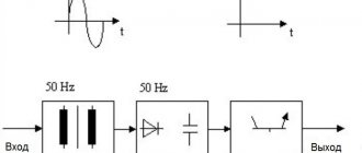
The circuit of the most common configuration of a pulse converter includes:
- network noise suppression filter;
- rectifier;
- smoothing filter;
- pulse width converter;
- key transistors;
- high frequency output transformer;
- output rectifiers;
- output individual and group filters.
The purpose of the noise suppression filter is to delay interference from the operation of the device into the power supply network. Switching of powerful semiconductor elements can be accompanied by the creation of short-term pulses in a wide range of frequencies. Therefore, here it is necessary to use elements designed specifically for this purpose as pass-through capacitors of the filter units.
The rectifier is used to convert the input alternating voltage into direct voltage, and the smoothing filter installed next eliminates the ripple of the rectified voltage.
In the case when a DC-DC converter is used, the rectifier and filter become unnecessary, and the input signal, after passing through the noise suppression filter circuits, is fed directly to the pulse-width converter (modulator), abbreviated PWM.
PWM is the most complex part of the switching power supply circuit. His tasks include:
- generation of high-frequency pulses;
- control of the block's output parameters and correction of the pulse sequence in accordance with the feedback signal;
- control and protection against overloads.
Network filter circuits for pulsed and high-frequency interference: 4 types of designs
Rule No. 2: high-quality UPSs must have a reliable filter for high-frequency signals in the design of the unit.
It is important to understand that high frequency pulses play a dual role:
- V/h interference can come from the household network to the power supply;
- high-frequency current pulses are generated by the built-in converter and exit it into the home wiring.
Reasons for interference in a household network:
- aperiodic components of transient processes arising from switching powerful loads;
- operation of nearby devices with strong electromagnetic fields, for example, welding machines, powerful traction motors, power transformers;
- consequences of suppressed atmospheric discharge pulses and other factors, including the superposition of high-frequency harmonics.
Interference impairs the performance of electronic equipment, mobile devices and digital gadgets. They must be suppressed and blocked within the switching power supply design.
The filter is based on a choke made of two windings on one core.
Chokes can be made in different sizes, wound with thick or thin wire on large or small cores.
It is enough for a novice master to remember a simple rule: a filter with a large magnetic circuit inductor, an increased number of turns and a wire cross-section works better. (Principle: the more, the better.)
The inductor has inductive reactance, which sharply limits the high-frequency signal flowing through the phase or zero wire. At the same time, it does not have much effect on the current in the household network.
The operation of the inductor is effectively complemented by capacitive reactances.
The capacitors are selected in such a way that they short-circuit the interference signals weakened by the RF choke, directing them to ground potential.
The principle of operation of the filter for high-frequency noise from penetration of input signals into the power supply is shown in the picture below.
Y capacitors are installed between the ground potentials with zero and phase. Their design feature is that in the event of a breakdown they are not capable of creating an internal short circuit and supplying 220 volts to the device body.
Between the phase and zero circuits, capacitors are placed that can withstand 400 volts, or better yet, 630. They are usually shaped like a parallelepiped.
However, you should be well aware that the UPSs in the voltage converter themselves correct the signal and interference practically does not interfere with them. Therefore, such a system is relevant for conventional analog blocks with output signal stabilization.
For a switching power supply, it is important to prevent RF interference from entering the household network. This feature is implemented by another solution
As you can see, the principle is the same. It’s just that capacitive reactances are always located along the path of the interference behind the inductor.
The third circuit of the high-frequency filter is considered universal. She combined elements of the first two. The Y capacitors in it simply work on both sides of each inductor.
The most expensive and reliable devices use a complex filter with additionally connected chokes and capacitors.
I immediately show the arrangement of filters on all circuits of the power supply: input and output.
Please note that a ferrite filter, consisting of two detachable half-cylinders or made of a one-piece structure, can be additionally installed on the cable coming out of the UPS and connected to the electronic device
An example of its use is a switching power supply for a laptop. This is already the fourth use of the filter.
Scope of application of a switching power supply
Pulse voltage converters are used in most cases instead of traditional transformers with semiconductor stabilizers. With the same power, inverters are distinguished by smaller overall dimensions and weight, high reliability, and most importantly, higher efficiency and the ability to operate in a wide input voltage range. And with comparable dimensions, the maximum power of the inverter is several times higher.
In such an area as DC voltage conversion, pulsed sources have practically no alternative replacement and are capable of working not only to reduce voltage, but also to generate increased voltage and organize a change in polarity. The high conversion frequency greatly facilitates filtering and stabilization of output parameters.
Network filter circuits for pulsed and high-frequency interference: 4 types of designs
Rule No. 2: high-quality UPSs must have a reliable filter for high-frequency signals in the design of the unit.
It is important to understand that high frequency pulses play a dual role:
- V/h interference can come from the household network to the power supply;
- high-frequency current pulses are generated by the built-in converter and exit it into the home wiring.
Reasons for interference in a household network:
- aperiodic components of transient processes arising from switching powerful loads;
- operation of nearby devices with strong electromagnetic fields, for example, welding machines, powerful traction motors, power transformers;
- consequences of suppressed atmospheric discharge pulses and other factors, including the superposition of high-frequency harmonics.
Interference impairs the performance of electronic equipment, mobile devices and digital gadgets. They must be suppressed and blocked within the switching power supply design.
The filter is based on a choke made of two windings on one core.
Chokes can be made in different sizes, wound with thick or thin wire on large or small cores.
It is enough for a novice master to remember a simple rule: a filter with a large magnetic circuit inductor, an increased number of turns and a wire cross-section works better. (Principle: the more, the better.)
The inductor has inductive reactance, which sharply limits the high-frequency signal flowing through the phase or zero wire. At the same time, it does not have much effect on the current in the household network.
The operation of the inductor is effectively complemented by capacitive reactances.
The capacitors are selected in such a way that they short-circuit the interference signals weakened by the RF choke, directing them to ground potential.
The principle of operation of the filter for high-frequency noise from penetration of input signals into the power supply is shown in the picture below.
Y capacitors are installed between the ground potentials with zero and phase. Their design feature is that in the event of a breakdown they are not capable of creating an internal short circuit and supplying 220 volts to the device body.
Between the phase and zero circuits, capacitors are placed that can withstand 400 volts, or better yet, 630. They are usually shaped like a parallelepiped.
However, you should be well aware that the UPSs in the voltage converter themselves correct the signal and interference practically does not interfere with them. Therefore, such a system is relevant for conventional analog blocks with output signal stabilization.
For a switching power supply, it is important to prevent RF interference from entering the household network. This feature is implemented by another solution
As you can see, the principle is the same. It’s just that capacitive reactances are always located along the path of the interference behind the inductor.
The third circuit of the high-frequency filter is considered universal. She combined elements of the first two. The Y capacitors in it simply work on both sides of each inductor.
The most expensive and reliable devices use a complex filter with additionally connected chokes and capacitors.
I immediately show the arrangement of filters on all circuits of the power supply: input and output.
Please note that a ferrite filter, consisting of two detachable half-cylinders or made of a one-piece structure, can be additionally installed on the cable coming out of the UPS and connected to the electronic device
An example of its use is a switching power supply for a laptop. This is already the fourth use of the filter.