I made a simple 24 volt computer power supply for use at home. It can output a voltage of 17V with a DC current of up to 3A. Using this scheme, you can make the same universal adjustable power supply for your home with your own hands.
WARNING: This project involves high voltage, be careful!
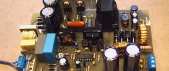
After my next power supply failed, it was decided to assemble a more powerful laboratory unit in its case.
The requirements for the new block were:
- Adjustable output voltage from 0 to 24 Volts;
- Output current up to 5A;
- Overload and short circuit protection;
- Current limit.
After that, I collected a number of power supply circuits and will write articles about these circuits one by one, but now we will look at the very first circuit that I assembled in literally 20 minutes. I would like to immediately note that this circuit does not comply with the specified standards, but perhaps we will consider it as an option for a simple power supply.
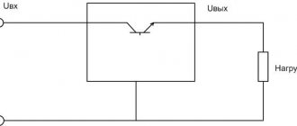
The circuit is quite simple and contains a power transistor for regulation; the upper range of the output voltage is determined by the rating (stabilization voltage) of the zener diode used, in my case a 15-volt zener diode.
If desired, the power switch can be replaced with a more powerful one; in my case, a 2N3055 type transistor was used, the dissipation power is 115 watts (I still have it from the first power supply.
If you do not have the required zener diode, then you can use two connected in series to obtain the required stabilization voltage. An electrolyte of 100 μF (parallel to the zener diode) is needed so that the latter does not make noise.
We must install the regulating transistor on the heat sink; during operation, a current of up to 3 Amps passes through it, so it will overheat quite strongly. Diode bridge - we select only taking into account the permissible current, it is better to take a couple of Amps with a reserve, as a result, the bridge must be designed for a current of at least 3 Amps. In this case, you can use either an assembly of 4 diodes or a ready-made diode bridge, which can be removed from computer power supplies. D226 diodes can be replaced with any standard rectifiers with a current of at least 1A. The variable resistor can have a value from 1 kOhm to 22 kOhm.
The output voltage is smoothly regulated, the lower limit is 0, this is quite good, since many power supplies have this limit of 0.8-1.5 Volts.
The transformer must provide an output voltage 3-5 Volts higher than the calculated voltage at the output of our unit, for example, if you expect to receive 15 Volts at the output, then a transformer is needed with a voltage of 18-22 Volts. Perhaps 3A is the maximum that can be obtained from such a circuit, the circuit does not have short-circuit and overload protection, there is also no way to limit the current, but the unit is quite good, can be used for amateur radio needs.
Sincerely - AKA KASYAN
DIY crafts for car enthusiasts
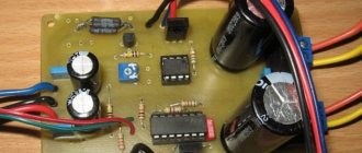
If you are looking for a simple, powerful, reliable and affordable laboratory power supply circuit, then this article is just for you. I strongly recommend this scheme for repetition, only
please assemble it using the printed circuit board that I made for you in order to avoid all sorts of errors during installation.
The basis of the circuit was taken from a foreign magazine, only I increased a little power, tested it in more detail, eventually added an additional power transistor on my own, and the board itself was naturally modernized. The result was an excellent power supply with good load capacity, and stabilization remained at a fairly high level.
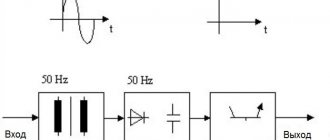
The main disadvantage of linear circuits is their low efficiency, and when designing such power supplies, problems arise with cooling the power transistors, so it is very desirable to use a transformer with several windings and a switching system.
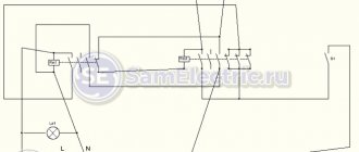
The simplest option is shown in the photo.
It is worth pointing out that now many people prefer switching laboratory power supplies whose efficiency can reach 90 percent or more, but linear power supplies are more valued. Professional linear power supplies are always supplemented with a winding switching unit.
The power supply can provide a stable output voltage from 0 to 35-38 volts, and the output current can reach up to 5-6 amperes.
By the way, the current is also stabilized, that is, the set current value will be maintained when the input and output voltage changes, and does not depend on the output load.
You set the current to 1 ampere, and even if there is a short circuit, it will be limited to one ampere.
And here is the actual modernized scheme.
I reduced the resistance of the current sensor to 0.1 ohm,
added a second power transistor in parallel with the first,
but in the emitter circuits of each transistor there is a current equalizing or ballast resistor.
Power transistors can be of any appropriate power, the collector current of the transistor is preferably 10 amperes or higher, while the power dissipation should be 100 watts or more.
Since this circuit is linear, I highly recommend using transistors in metal cases, or at least transistors in a TO247 case, so that there are no problems with heat transfer.
In the circuit we have three powerful resistors, I advise you to take ballast ones of 5 watts, but a current sensor of 10 watts wouldn’t hurt.
I advise you to take ballast resistors with a resistance of 0.22 Ohm; unfortunately, they ran out, so I set them to 0.1 Ohm, but if the transistors have the most identical parameters, then this solution is even better.
In my case, I initially used 2SD209 switches as power transistors; essentially, they are an analogue of MJE13009 switches, both options are very often used in computer power supplies.
Each such transistor can dissipate 100-130 watts of power, but only if there is good cooling and you are confident in the authenticity of the transistors, but their main problem is too low current gain, only about 20.
I highly do not recommend setting similar keys for several reasons. Firstly, the adjustment will be nonlinear due to the low gain of the switches; for the same reason, it is difficult to control such transistors, so the driver switch will heat up harshly and will need a small radiator.
I highly recommend transistors in metal cases, like 2N3055, they are ideal for such circuits. Metal case, decent power and collector current, and current gain of about 200, just what you need.
I ended up installing 2SD1047 switches; they have decent gain and are used both in power supplies and in the output stages of low-frequency power amplifiers.
It is convenient to use a common radiator for keys; moreover, there is no need to insulate the keys with gaskets, since the substrates or collectors in our circuit are common.
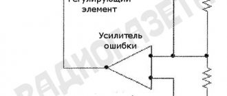
After applying power to the stabilizer circuit, you need to set the maximum output current by rotating this trimming resistor,
let’s say 5 amperes, then we set the maximum output voltage, it all depends on what kind of power source you have, what its current and output voltage are, that is, this stabilizer can be easily adjusted to any power source.
Enter your email and receive emails with new crafts.
Now we supply power to the input of the stabilizer and check the minimum output voltage - as we see, it is 0 volts, which is what we needed to prove, the adjustment is very smooth throughout the entire range.
Now let’s check the current, the minimum output current can be dropped down to 0, and the circuit can produce a maximum of 5 amperes without problems.
One of the most important tests is how much the output voltage will drop at certain currents, well, let's see, but before that it is important to point out that there will be voltage drops on the wires, the ammeter measuring shunt and on the stabilizer itself, as well as on the current equalizing resistors, that is, on There will be drawdowns in the indicated areas, this is the case with any power source.
Current 1 ampere, drawdown about 0.1 volt,
current 3 amperes drawdown only 0.4 volts
and finally, the maximum current is 5 amperes, the drawdown is 0.65 volts, without measuring equipment these figures would be much less.
Let's check the stability of the output voltage during sudden changes in the input voltage, for example, changes in the network.
As you can see, the stabilizer holds up well; when the input voltage changes by 10 volts, the output changes only by 50-70 millivolts.
And now the ripple at the output, with a total of 1 ampere pulsation is no more than 20 millivolts, with a current of 3 amperes - about 25-30 millivolts,
and with a maximum current of 5 amperes, output ripple of about 50-60 millivolts, you will agree that this is a good indicator for a power supply of this level.
Archive for the article; .
Author; Aka Kasyan.
Popular;
- A simple laboratory power supply made from an old computer power supply.
- Power supply with voltage and current regulation
- Powerful, regulated power supply for lm317
- Simple control unit for charger
- Charger from power supply from computer
- Universal power supply 0-30 V with current adjustment from 0-3 A
- Garage power supply for repair work
- Charger made from PSU LED strips.