Types of voltage
In most garages, the electrical voltage is 220 V. This is enough for lighting and a power outlet group. Such an electrical network allows the use of most power tools and appliances.
Sometimes a network with a voltage of 380 V is installed in garages. This may be necessary for the operation of electric heating devices, machine tools and welding equipment that require three-phase power with a voltage of 380 V.
Selecting equipment for the device
To create a project for an electrical panel in a garage, you need to build a list of necessary equipment. All devices that will be powered from the network must be taken into account:
- lighting system;
- ventilation;
- household appliances;
- various power tools;
- signaling.
Once the list of equipment that will be used in the garage has been compiled, the compilation project can begin. It is necessary to take into account what the maximum load current will be. In some cases, you have to give up various devices.
What's included in a garage wiring diagram?
The electrical wiring diagram in the garage should include the following basic elements:
- distribution board at the input;
- accounting, protective and automatic devices;
- cables and wires;
- switches and lamps;
- socket group.
If necessary, you can add other elements to the circuit, such as heating, cooling and other systems. Examples of circuits can be studied from photos of electrical wiring in the garage. They will help you understand the basic requirements, wiring methods, installation options and other nuances.
What is an electrical panel?
An electrical distribution panel is a small panel that is used to install equipment responsible for supplying a room with electricity. Many people consider such devices to be very convenient, since they can install all the necessary switches and electrical mechanisms. This makes it easier to disconnect the garage from electricity, as all you need to do is use a few levers.
When making panels, they use lightweight materials, which simplify their installation in the garage. Most models are equipped with special security doors that are locked with a key. They help prevent accidental contact with equipment inside. Some modern models have doors that close hermetically. This will protect the switchboard from precipitation if it is installed outside the garage.
Power input
A distribution panel is installed at the input. In some cases, it is mounted on the outside of the building, which may be due to the peculiarities of the electrical supply to the garage.
«> «> «> «> «> «>
Usually the shield is mounted next to the entrance for easy shutdown when leaving the facility. The panel must allow placement of all required protective and distribution devices. The panel also houses an electricity meter (meter) if the garage is located on the territory of a garage cooperative. In suburban areas, one meter is usually used for all buildings.
You can make the shield yourself from a profile and sheet metal or purchase a finished product.
Differential machines
Designed to automatically shut off power supply in case of overload to protect against fire. They also allow you to quickly turn off the power supply if it is necessary to modify the electrical wiring. It is customary to divide the premises into groups of consumers, for each of which their own machine is installed. At a minimum, install one circuit breaker for lighting and socket group.
If there are many consumers, and accordingly there are several outlet groups, a separate machine is installed for each of them. The rating of the machine is determined based on the maximum load and wire cross-section.
Designed to protect against leakage current. The latter occurs when the circuit insulation is damaged. The use of RCDs is especially important in garages with inspection pits, where work with power tools is carried out. There is usually high humidity in the pit, which increases the likelihood of a leakage current.
«> «>
Garage Wiring Diagram: Planning Tips
Lighting in a garage plays a very important role, especially if the garage is used not only for storing the car, but also for regular maintenance. The electrical circuit of a garage should not only provide comfortable working conditions with electrical appliances and the correct placement of lighting elements, but also be safe for the owner.
In this article we will tell you how to correctly draw up an electrical circuit and describe the basic rules for placing important elements.
Electrical Design Principles for Garages
A simple garage wiring diagram provides for the external location of all elements, such as cables, sockets, electrical distribution panels and lights (see Garage Lights). Many people try to hide cables by laying them in the walls before plastering or covering them with finishing materials.
But practice has shown that such a garage wiring diagram is not practical and the best option would be surface wiring. To protect the wire in the most likely places of damage, plastic or metal corrugated tubes are used, and special plastic boxes are used for decorative concealment.
For your information. The electrical circuit of the garage should be laid out in such a way as to provide quick access to all elements for their convenient replacement, since very often, with active and varied use of the garage, there is a need to move sockets or lighting elements to another place. Open wiring eliminates the possibility of damage when drilling into walls.
Step-by-step plan for building an electrical network
The procedure for drawing up an electrical diagram for a garage is as follows:
- First of all, you need to draw a plan of the garage space and graphically indicate the location of the main distribution board, indicating the distance from the walls. Next, the electrical wiring in the garage is distributed, the diagram of which should contain cable routing and installation locations for lighting fixtures.
- The plan then indicates the exact location of the workbench and other stationary electrical appliances, such as a lathe, welding machine, compressor, and so on.
- Then a diagram is made of each wall on which the outlet will be placed. The diagram shows the location of electrical appliances, their height and the plan for connecting the socket to them.
For your information. The correct type of electrics in the garage would be the design of which would include both general lighting of the entire room with ceiling lamps and local lighting. The switch for general lighting should be installed at the exit at such a distance that you can reach it with an outstretched arm, while taking one step from the entrance. Switches for local lighting are mounted directly on site, at eye level.
- An electrical distribution board is also installed at the entrance, so that the room can be completely de-energized when leaving it.
- A distribution box must be installed near the general lighting switch so that each of the lamps has a separate power cable. If all lamps are connected in parallel from one cable, then a junction box is not needed.
- Garage wiring diagrams should include instructions for using the right type of cables depending on the load. Copper cables with a core cross-section of 1.5 mm are designed for a load of 3 Kilowatts, cables with a cross-section of 2.5 mm can withstand a load of up to 5 Kilowatts. When choosing a cable, you should always make a load reserve of 20-25%.
- It is strongly recommended not to connect sockets in series, one from the other. The best option would be to run a common cable from the panel and connect each socket to it separately through a distribution box, as shown in the photo below. Usually the cable with wiring and boxes is laid under the ceiling.
- It is recommended that the electrical connection diagram in the garage for sockets provide for the presence of an RCD device with a separate circuit breaker. Such a device will protect the user from accidental electric shock resulting from damage to the wiring or electrical appliance. In addition, the price of such a device is your life. The overload current to cut off the power supply should not exceed 16 Amps for a cable with a cross-section of 1.5 mm, and 25 Amps for a cable with a cross-section of 2.5 mm.
Important. The electrical wiring diagram for a garage with a wooden or other combustible base should include the installation of protective metal boxes for laying cables. These boxes will prevent the casing from igniting in the event of overheating and fire of the cable.
The difference in circuits for 220 and 380 volts
Many garage cooperatives, in addition to the standard 220-volt electrical network, can provide garages with separate 380-volt wiring to power high-power electrical equipment. The safety instructions assume that there is one incoming socket in each room of the garage cooperative, but if necessary, you can make additional wiring for several sockets in the right places.
With a 220-volt electrical circuit, two or three cables are brought into the garage: phase, neutral and grounding (see Grounding in the garage and rules for performing work). In some cases there may be no grounding.
As can be seen from the diagram, the phase passes through the main circuit breaker to the electricity meter, then goes to the lighting through conventional 25 or 32 Ampere circuit breakers, or to sockets through an RCD device. If you do the electrical wiring in the garage yourself, the circuit must include two automatic devices for lighting the room and the inspection pit separately.
When using a 380-volt line, there may be 4 or 5 wires entering the room, three of which are phase, one is a neutral wire, and possibly a fifth ground wire. In this case, you will need a three-phase machine to enter the room and install a three-phase meter.
The photo shows that a common circuit breaker after the meter divides the network into 220 and 380 volts. With this connection, 220 volts are diverted to regular sockets and lighting, and 380 volts are diverted through a separate three-phase circuit breaker to high-power sockets, which must be marked with the appropriate pictogram.
In this article, we looked at how to do wiring in a garage with your own hands, the diagrams clearly showed the connection features, and the video material presented will show the practical part of this work.
Do-it-yourself electrical wiring in the garage
Even in the simplest garage box you need to install lighting. Cars should be periodically inspected, oil changed, and tinted. And getting in and out of a dark room is inconvenient and unsafe. You can connect lights and sockets in the garage yourself.
- How to properly plan your garage's power supply
- Rules for creating a schema
- How to make a project
- Selection of wires and cables by power
- Required tools for installation
- Installation of electrical wiring
- Safety regulations
Preparation for work
The preparatory procedure includes the selection of the necessary materials and tools that will be needed to carry out installation work on laying, fastening and connecting electrical wiring in the garage.
List of tools:
- flat and Phillips screwdrivers of different sizes;
- pliers;
- round nose pliers for making accurate connections to machines;
- hammer drill, grinder for grooves, holes for sockets, as well as installation of mounting brackets for cable fastening;
- voltage indicator to check the absence of potential and safe operation, since even with the input circuit breaker turned off, one cannot be absolutely sure that there is no voltage in a separate section of the circuit (the current-carrying elements of the circuit breaker are hidden in the housing, so the installer cannot verify the reliability of the connection of its contacts, that is no visible circuit break);
- hammer, chisel;
- insulating materials (insulating tape, PVC pipe, etc.).
List of materials needed to organize electrical supply to the garage:
- current-limiting and protective devices for supplying voltage and its control (circuit breakers, RCDs, stabilizers);
- electric meter with electrical panel;
- cable products (wires);
- distribution boxes;
- lighting switches;
- sockets
After acquiring all the necessary materials and tools, you can begin preparatory work and directly laying the wiring in the garage with your own hands.
How to properly plan your garage's power supply
To service 1-2 cars, it is enough to install several lighting fixtures and a power outlet group to connect power tools. The power of the latter is small, so single-phase power supply with a voltage of 220 V is installed in the garage.
If the garage is a car repair shop and powerful equipment is installed here - heating boilers, welding devices, machine structures - you need to install three-phase power with a voltage of 380 V.
It is also necessary to correctly calculate the number of lighting fixtures; this depends on the size of the box, the presence or absence of a basement and inspection hole. It is also important to keep in mind the type of garage. If it is, for example, part of a garage cooperative, its own substation is installed to service the garages. If the building is located on a summer cottage, the cable connection is carried out from the house.
Charging device
It is better to choose an electrical panel that can be connected to the charger. It is not uncommon for garages to use a charging device. Features of such electrical panels:
- It must be a power type device. If this is not possible, the electrical panel with charging can be connected to the transformer responsible for the basement.
- A do-it-yourself electrical panel with charging is often a device that should be made according to the same circuit as the LATR 2 autotransformer. It can only operate with a load of 2 A. The power of such a device is 500 W. In this case, the transformer voltage does not exceed 250 V.
A transformer, factory-made or home-made, that is used to charge the battery has several advantages:
- Isolation is performed galvanically. In this case, the voltage is divided into primary and secondary.
- Constantly increasing the output power of electricity. The transformer itself is capable of delivering only 2 A. That is why it needs to be increased.
Transformers of type T-1 operate according to the following principle:
- The voltage is supplied to the VD-1 rectifier via a three-way toggle switch.
- Then it stabilizes. Passing through the toggle switch, voltage is supplied to the terminals used.
- It is necessary that the power toggle switch is located at the output of the toggle switches. Using this device, you can turn off the current supply to the terminals at any time.
- Terminals that output 12 V are needed to ensure stable operation of the device and additional motors that are present in the car.
- Terminals capable of delivering 27 V may not be used very often. With their help, it is possible to charge several batteries simultaneously. At such terminals the current strength will be lower than in the case of the previous ones.
The electrical panel diagram in the garage when using the T-1 transformer has the following features:
- The primary winding is connected to terminals located separately from each other. They must be separated from those terminals to which the secondary winding is led.
- The terminals connected to the secondary winding must be combined with the main line intended for lighting the basement.
- In addition, it should be remembered that the secondary winding of the transformer is equipped with a 24 V output. This condition is necessary since the system must be continuously supplied with a current of 15 V.
- The network load is distributed between two types of terminals.
- The voltage can be easily made normal using special diodes.
Attention! When connecting wires in an electrical panel, twisting should be avoided. To do this, you need to use special devices - terminal blocks. Their use ensures reliable contacts.
Rules for creating a schema
DIY garage wiring includes the following components:
- power distribution board, preferably with an RCD;
- metering devices;
- wires;
- lighting devices - lamps, spotlights, and switches;
- sockets
If there are other consumers in the garage, such as a heater or heat gun, they are also included in the circuit.
How to make a project
The electrical wiring diagram is developed taking into account the dimensions of the room and the vehicle, the installation location of electrical appliances and the location of the panel. The plan is displayed on the drawing, where the true dimensions are indicated.
To calculate the correct scheme, a step-by-step algorithm is used.
Draw up a plan for the garage to scale. For each wall, floor and ceiling they make their own sketch.
- Mark the coordinates of each lighting fixture. If the garage has a basement or inspection hole, they are equipped with their own lamps. It is taken into account that an ultra-low voltage current of 42 V or less can be used to illuminate them. To do this, step-down transformers are included in the circuit. Lamps or tools that are intended to be used in the inspection pit must be designed for this voltage.
- Mark the installation location of the distribution panel and use the diagram to find the optimal routes for laying the wires. Here they also determine where it is more convenient to install sockets and switches.
- Depending on the number of electrical appliances, a protection system is developed: RCD, voltage control relays, voltage limiters, step-down transformers.
- If the garage is a separate building, provide grounding along the circuit and indicate this on the plan.
Typically, car owners are limited to installing an RCD in the distribution panel. But if overhead wiring is installed in the garage, you need to introduce voltage limiters into the circuit - they prevent a sharp increase in voltage. If the garage box is located in a long row of cooperative ones, it is better to install a control relay.
Home craftsmen experimenting in their garages sometimes cause their neighbors to break zero.
Connection diagram inside the shield
A typical version of the garage panel diagram is presented.
The ratings of the circuit breakers are selected so that in case of a short circuit in the line or the permissible load on the cable is exceeded, the load is disconnected before the conductors heat up to the melting temperature of the insulation. The RCD parameters indicate a leakage current of 30 mA, this corresponds to a safe value to prevent electric shock.
Automatic machines rated 16 A are used on lighting lines or sockets for connecting hand-held power tools. A line with a 32 A automatic machine is designed to use a more powerful load, for example, a welding machine or a heat gun.
You will notice that connecting and installing a garage electrical panel yourself does not pose any particular difficulties if you follow safety precautions and adhere to the connection diagram.
Selection of wires and cables by power
To make the correct electrical wiring in the garage, the total and individual power of the consumer is determined. The main supply cable must match the total value. In addition, the way in which electricity is conducted is taken into account. So, for a private house, a SIP is enough - aluminum for 16-24 square meters. mm or copper for 8–10 sq. mm.
To illuminate the main room, you need lamps with a power of up to 500 W; a copper cable of 1.5 square meters is enough for this. mm.
The sockets are designed for 16 A, so they use a 2.5 sq.m. wire. mm.
The more powerful consumers are in the garage, the larger the cable cross-section needs to be used. General recommendation: install only wires with copper cores.
List of necessary items
To install the wiring you will need:
- Shield body
- Slot machines by number of lines
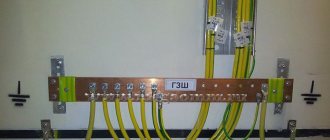
- Busbars for connecting zero and ground wires
- 1.5 mm2 cable for lighting
- 2.5 mm2 cable for sockets
- Cable duct or corrugation with mounting brackets
- Sockets, light switches
When installing wiring using grounding, you will additionally need a Residual Current Device.
ATTENTION! To ensure your safety, it is advisable to install an RCD in the electrical wiring, since this device protects against current leakage to the grounding bus (the housing of electrical appliances), and therefore protects against electric shock.
Required tools for installation
For wiring in a private garage according to a 220-volt circuit, you will need:
- hammer drill and electric drill, grinder;
- hammer, chisel;
- pliers, side cutters, screwdrivers;
- electrical tape and an indicator screwdriver.
To work with wires, it is better to use tools with rubberized handles.
Installation of electrical wiring
Installation of electrical wiring in the garage begins with preparation. They check the circuit, making sure, for example, that the cables are placed only vertically and horizontally, the sockets are placed at a distance of 60 cm from the floor, and so on. Installation locations are marked on the walls and ceiling. Before installation, flammable materials and large objects are removed from the premises.
- The wire to the garage is laid underground at a depth of 30 cm below the freezing level of the soil. The cable is laid in a corrugated plastic pipe. You can connect the garage to the electrical network by air: in this case, the wire is stretched between the support posts.
- The cable is inserted into the box through a hole in the wall with a diameter of 20–30 mm. The hole is made with a hammer drill, and the wire is laid through a PVC pipe.
- In the garage, grooves are made using a chisel and hammer according to the marks in the walls. The wires are laid in plastic tubes. If the garage is wooden, the cable is laid openly.
- For the shield, 4 holes are drilled in the wall and the device body is secured. Before this, all modules are removed from the device. After installation, install the DIN rail and secure the modules back. It is recommended to label them.
- The upper contacts of the modules are the input for phase wires, the lower ones are for outlets and lighting.
- Connect the neutral wires leading from the meter and the RCD. The last thing to connect is the power cable.
- Install lamps, sockets and switches. Connect the wires to the consumers.
- Check the insulation and correct connection of devices. Apply power and test the system.
The 380 V line is made of 4- or 5-core copper cable.
Safety regulations
When doing wiring in a garage, follow the following safety rules:
- the cable inside the garage is installed in a groove or protective box;
- insulating corrugations are used in a metal box;
- the lighting and power group lines are routed to different circuit breakers;
- The electricity supply line of the inspection pit is equipped with its own protection;
- When choosing lamps, devices and wire insulation, the destructive effects of dampness, low temperature and aggressive substances are taken into account.
Installing electrical wiring in a garage is quite a difficult job. It is important not only to actually lay the wire, but also to calculate the correct circuit, select cables with the required cross-section, and organize a protective system.
How to do electrical wiring in a garage. Basic principles
There is no point in building a garage without supplying electricity to it. What should a garage wiring diagram include and what electrical appliances should be used? Let's look at how to do electrical wiring in a garage . The standard electrical circuit for any garage includes:
- Laying cables.
- Installation of means of protection against electric shock.
- Lighting connection.
- Placement of sockets.
Supplying electricity to the garage
Every garage cooperative has a main electrical panel. From it cables are routed through the boxes. The ideal option would be to connect the cables from each box directly to the main panel. However, due to the large number of garage boxes and their remoteness, such a connection is not feasible due to high costs. Therefore, other options are used.
The most common method is to route cables from the switchboard to a group of boxes. A group panel is installed on each group, equipped with a switch with fuse links or an automatic circuit breaker designed for high operating current.
A cable is laid from the local panel to the electrical panel in the garage. The structure of the local panel is similar to a garage panel, but it does not have an RCD and an electric meter. To lay the cable, it is placed in a corrugated pipe or metal hose and securely attached to the wall at the maximum possible height. The pipe protects the cable from accidental mechanical damage. For the same purpose, when inserting a cable through a garage wall, protective sleeves are used.
Electrical connection to the cable in the group panel is made only after the final installation of the panel in the garage. All work must be carried out when tension is relieved at the work site.
There is another option for connecting the cable from the garage to the main line. This method is used when, instead of group switchboards, the distribution of electrical cables throughout the territory of the garage cooperative is carried out along lighting poles. In this case, the cable from the garage panel is connected to the main lines on the pole. The connection is made using special clamps or punctures.
The second option is less preferable, because for the safety of work during connection it is necessary to de-energize a large number of boxes. The work itself is carried out at height, which creates additional danger.
Wiring
If at the time of construction or reconstruction of the garage hidden wiring was installed in the walls and it was not damaged, then you can use it. If you don’t have one, you shouldn’t waste your energy on stripping. External wiring can be done. Cables should be laid in a metal corrugation, cable duct or in a self-extinguishing tube. It is advisable to use non-flammable cable VVGng or NYM.
For lighting, a copper cable with a cross section of 3X1.5 mm² is suitable; for sockets above the workbench - 3X2.5 mm²; for sockets with heavy loads - 3X4 mm².
Since they not only park a car in a garage, but sometimes also work, it is necessary to ensure electrical and fire safety. To do this, a differential circuit breaker or RCD is used together with grounding.
A grounding wire with a cross-section of at least 3 mm² leads from the common panel. If there is no grounding bus in the shield, point grounding is done.
At the entrance to the garage, a panel is usually installed in which an RCD with a rated current of no less than that allowed for a garage in a cooperative is installed. If the garage is private, then the optimal current will be 32 A. When using a separate 32-40 A RCD, after it a regular 25 A machine is installed on the sockets, and 10 A for lighting. This is quite enough to connect basic power tools to the sockets.
What type of shield can be installed in the garage?
Electrical panels are produced in a metal or plastic case. You can use a plastic case, but given the presence of a large number of metal objects in the room, it would be safer to buy a metal box. This reduces the likelihood of mechanical damage to the housing.
If the garage is not heated, a large amount of moisture accumulates in the air. To prevent corrosion of the installed elements, the climatic design of the shield must be U3 (for installation in unheated rooms and operation at temperatures from minus 40 to plus 40 degrees).
The housing must be equipped with a locking device, and on its outer side there must be a bolt for connecting the grounding device.
Lighting organization
The more light in the room, the better, but you shouldn’t fill the entire ceiling with lamps. To obtain uniform lighting, you need to correctly position several lamps.
For optimal lighting, it is more than enough to have the following in the garage:
- General lighting that allows you to clearly see what is happening in the room.
- Local lighting in the workbench area.
- Lighting in the inspection hole, if available.
All lamps must be protected from damage due to mechanical stress and have a safety level of IP65. As one of the lamp installation schemes, we can recommend the placement of linear fluorescent lamps under the ceiling. these lamps will provide general lighting. Lighting of work areas is carried out using protected LED directional lamps with an operating voltage of 12 V. Such lamps do not heat up, and a voltage below 36 V prevents them from causing electric shock in the event of a breakdown. Plus they are energy efficient.
Use of electrical equipment
If you like to stay in the garage for a long time and make something with your own hands, then you will certainly have the necessary minimum of power tools. To be prepared for this, it is better to plan the load on the electrical network in advance and take it into account before wiring the garage. And in order to correctly calculate the cable cross-section, it is necessary to accurately determine which electrical appliances will be used indoors. The total power of all electrical appliances must be multiplied by a factor of 1.2 to ensure a power reserve of 20%.
Approximate power of power tools: