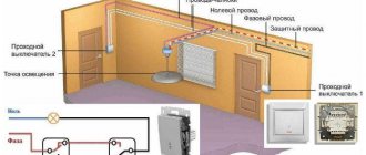
What does a pass-through switch look like and work?
A pass-through switch is a device that allows you to control one light source using two different switches. This type of design looks like a regular switching device.
Types of two-key pass-through switches
The difference between a pass-through device and a standard one is that a regular switch performs the function of simply breaking (turning off) the lighting circuit, while a pass-through switch switches from one electrical circuit to another. Because of this, the mechanism is also called a toggle switch.
Images in the form of arrows are applied to the keys of pass-through devices, which indicate the direction for turning the device on and off. In this case, the light can be turned on from one point, and from another point it can be turned off, no matter what position the key is in. That is, unlike standard designs, the position of the device keys is not fixed on/off.
Purpose of the changeover switch
Reversible equipment is installed because of its durability and ease of use.
Reversible devices are used:
- in multi-storey buildings (on stairwells of entrances, in multi-storey cottages);
- at different ends of long corridors of apartments and hotels (if it is necessary to turn on the light when entering the room, and turn it off when leaving);
- in the bedrooms (by the bed and by the front door);
- in passages (in the metro);
- in basements;
- in areas with a large area (in sports complexes, hospitals, auditoriums, assembly halls).
Example of use in the photo below:
Example of using a changeover switch
Types of pass-through switches
Switches vary depending on the type of device:
- Keyboards (standard type with any number of keys used).
- Touch (requires a separate circuit for installation).
You can also classify the device by type of wiring:
- External wiring.
- Internal wiring.
Depending on the number of keys, switches are:
- single-key (with one working switching element);
- two-key (with two working switching elements);
- three-key (with three switching elements);
- cross with 1 or 2 keys (when turning on the lighting from several places).
Types of pass-through switches
The devices differ in the structure of the contact terminals:
- With screw terminals.
- With spring clamping elements.
Prices for two-key wall switches
Two-key wall switch
Operating principle of the equipment
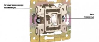
The single pass-through switch is equipped with three contacts in each of the operating mechanisms. The contacts are the connecting links between two system switches; with their help, the current is transferred from one circuit to the next, as shown in the diagram:
Connection diagram for pass-through switch
After changing the position of the mechanism, the current is directed to a specific terminal. One of them always remains closed.
For the light source to work, both devices must be locked in the same position.
Items required to connect a standard pass-through switch:
- distribution box (a box into which the ends of the wires are inserted);
- two conventional single-key switches;
- wires (the number depends on the type of connected equipment);
- any lamp, lamp or chandelier.
Grounding from the box is carried out directly to the light source. The phase is combined with the common terminal of one block, and its output contacts are connected to a pair of the same elements of the other. Next, the wire from the second switch goes back to the box, after which voltage is supplied to the lighting fixture. When installing equipment, switches are placed in boxes, after which a lighting device is installed, from which a two-core cable is taken out. At an accessible distance there is a distribution box to which the wires are connected.
Connecting two-key pass-through switches
A rocker switch with two operating keys consists of a pair of single structures united by a protective housing. The mechanism functions similarly to a single-key device.
Connection diagram for a two-key pass-through switch
The finished device, consisting of a pair of two-key elements, makes it possible to control two light sources independent of each other.
Connection diagram for a two-key pass-through switch from two places
If it is necessary to connect several changeover devices, choosing a two-key device will be beneficial due to the saving of cables and junction boxes.
Prices for switches (from 2 places)
Switch (from 2 places)
Video - Pass-through switch, how to connect, connection diagram for pass-through switches
Three-seat control scheme
Undoubtedly, this is a disadvantage of such a system. See also:. Disconnect the apartment or house from power. For example, in a three-story house, on each floor you can control the lighting on the stairs where needed.
Install decorative device panels.
The procedure for installing a circuit with two-key pass-through switches Both switches are installed in socket boxes in the walls, two three-core contact cables are supplied to each of them, because 6 A three-core cable is also supplied to each lamp The ends of the cables are connected inside the junction box according to the connection diagram As you can see, there is absolutely nothing here complex. Install decorative device panels.
A phase is supplied to the first pass-through two-key switch, and then according to the diagram and instructions on the switches themselves. Picture 1.
Since there will be four connected wires in the junction box. To avoid this, the lighting in the hallway is turned off with a timer.
If your wiring goes under the ceiling, you will have to lower the wire from there to each switch, and then lift it back up. In general, the thing is convenient and necessary. However, a switch with three terminals will no longer work here. 2 key pass-through switches from 3 places connection diagram
How does a switch with two keys work?
The equipment has a total of 12 contacts, 6 for each double switch (2 inputs, 4 outputs), therefore, to connect equipment of this type, you need to take 3 wires for each key of the device.
Switch diagram:
Switch circuit
- the device consists of a pair of independent contacts;
- The upper contacts of the device N1 and N2 are switched to the lower ones by pressing the keys. The elements are connected by a jumper;
- the second contact of the right switch, shown in the diagram, is in phase;
- the contacts of the left mechanism do not intersect with each other, joining two different sources;
- 4 cross contacts are combined in pairs.
The two-key switch is installed as follows:
- A pair of double mechanisms are installed in socket boxes in selected areas.
- For each light source, a separate three-core cable is placed in the socket box, the cores of which are cleared of insulation by about 1 centimeter.
- In the diagram, the cable cores are designated as L (phase), N (working zero), ground (protective).
- The device is equipped with markings, which simplifies the task of connecting wires to the switch terminals. The cores are connected to the terminals in pairs.
- The bundle of wires is carefully placed in the socket box, after which the switch mechanism, frame and cover of the protective housing are installed.
What the marking looks like:
Two-key switch markings
Connection diagram example:
Connection diagrams
To make the work process easier, it is recommended to select wires of a certain light. There is color coding of wires for Russia and other CIS countries. Also, a beginner can learn to distinguish cables from it. According to Russian markings, yellow and green colors are used for “ground”; the neutral cable is usually marked with blue. The phase may be red, black or grey.
Video - Connection diagram for a two-key pass-through and crossover switch from two or more places
Three-key equipment diagram
When installing a triple device, intermediate (cross) switches are used, which are connected between the two side elements.
Three-key equipment diagram
This switch is equipped with two inputs and outputs. The cross element can transfer both contacts at the same time.
Triple equipment assembly process:
- Ground and zero are connected to the light source.
- The phase is connected to the input of one of a pair of pass-through structures (with three inputs).
- The free wire of the light source is connected to the input of the other switch.
- The two outputs of one element, which has three contacts, are combined with the input of a cross device (with two pairs of outputs).
- The two outputs of the pair mechanism (with three contacts) are combined with the other pair of terminals of the next switch (with four inputs).
Video - How to connect a 3-key switch
Scheme of a two-key pass-through switch from two places
(light control from two or more points)
How to connect a pass-through switch (light control from two or more points)
Current electricity prices make you think about saving where you never even thought about it before. For example, lighting on the stairs. It doesn’t matter if it’s in a private or multi-storey building, you still need to pay. Previously, they simply left the light on. Today you think about turning it off, but running up and down is also not fun. It turns out there is a solution. To prevent the lights from being on constantly, there are schemes for controlling the lamps from several places. That is, one or more lamps can be turned on and off from several points. Special switches are needed for this. They are called walk-throughs. Sometimes the names “duplicate” or “change-over” are found. All this is one type of electrical equipment. They differ from ordinary ones in a large number of contacts. Accordingly, the connection diagram for the pass-through switch is more complicated. However, you can figure it out.
What does a pass-through switch look like and work?
If we talk about the front side, the only difference is: a barely noticeable arrow on the up and down key.
What does a single-key pass-through switch look like? You see there are double arrows
If we talk about the electrical circuit, everything is also simple: in ordinary switches there are only two contacts, in pass-through switches (also called changeover contacts) there are three contacts, two of which are common. There are always two or more such devices in the circuit, and they are switched using these common wires.
The difference is in the number of contacts
The operating principle is simple. By changing the position of the key, the input is connected to one of the outputs. That is, these devices have only two working positions:
- input connected to output 1;
- input is connected to output 2.
There are no other intermediate provisions. Thanks to this, everything works. Because the contact switches from one position to another, electricians believe it is more correct to call them “switches.” So a pass-through switch is also this device.
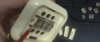
In order not to rely on the presence or absence of arrows on the keys, you need to inspect the contact part. Branded products should have a diagram on them that allows you to understand what type of equipment you have in your hands. It is definitely found on products from Lezard, Legrand, and Viko. They are often absent on Chinese copies.
This is what the changeover switch looks like from the rear
If there is no such diagram, look at the terminals (copper contacts in the holes): there should be three of them. But not always on inexpensive copies the terminal that stands alone is the input. They are often confused. To find where the common contact is located, you need to ring the contacts with each other at different key positions. This must be done, otherwise nothing will work, and the device itself may burn out.
You will need a tester or multimeter. If you have a multimeter, set it to sound mode - it beeps when there is contact. If you have a pointer tester, ring for a short circuit. Place the probe on one of the contacts, find which of the two it rings with (the device beeps or the arrow shows a short circuit - it deviates to the right all the way). Without changing the position of the probes, change the position of the key. If the short circuit is missing, one of these two is common. Now all that remains is to check which one. Without switching the key, move one of the probes to another contact. If there is a short circuit, then the contact from which the probe was not moved is the common one (this is the input).
It may become clearer if you watch a video on how to find the input (common contact) for a pass-through switch.
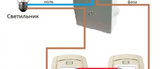
Connection diagram for a pass-through switch from two places
This scheme is convenient in a two-story house on the stairs, in a passage room, in a long corridor. You can also use it in the bedroom - turn off the overhead light at the entrance and near the bed (how many times did you have to get up to turn it on/off?).
Electrical diagram for switching on a pass-through switch from 2 places
Zero and ground (if any) are connected directly to the lamp. The phase is supplied to the output of the first switch, the input of the second is connected to the free wire of the lamp, the outputs of the two devices are connected to each other.
Looking at this diagram, it is easy to understand how the pass-through switch works. In the position shown in the figure, the lamp is on. By pressing the key of any of the devices, we break the chain. In the same way, when in the off position, by moving any of them to another position, we will close the circuit through one of the jumpers and the lamp will light up.
To make it clearer what to connect to what, and how to lay the wires, here are a few images.
Connecting wires on a pass-through switch
If we talk about the room, then you need to lay the wires approximately as in the photo below. According to modern rules, all of them should be located at a distance of 15 cm from the ceiling. They can be placed in mounting boxes or trays; the ends of the wires are inserted into mounting boxes. This is convenient: if necessary, you can replace a broken wire. Also, according to the latest standards, all connections occur only in installation boxes and using contactors. If you make twists, it is better to solder them and wrap them well with electrical tape on top.
The return wire of the lamp is connected to the output of the second switch. White indicates the wires connecting the outputs of both devices.
How to route wires around the room
How to connect everything in the terminal box is described in the video.
3 point circuit
To be able to turn the light on/off from three places, you need to buy a cross (cross) switch for two switches. It differs from those described earlier by the presence of two inputs and two outputs. It switches a couple of contacts at once. See the figure for how everything should be organized. If you understand the above, this one is easy to understand.
Electrical circuit for controlling a lamp from three points
How to assemble such a circuit? Here's the procedure:
- Zero (and ground, if any) is connected directly to the lamp.
- The phase is connected to the input of one of the pass-through switches (with three inputs).
- The input of the second is fed to the free wire of the lamp.
- The two outputs of one three-pin device are connected to the input of a crossover switch (with four inputs).
- The two outputs of the second three-pin device are connected to the second pair of switch contacts with four inputs.
- the middle switch has more wires and a completely different connection diagram;
- The design of such a switch is somewhat different from the extreme one.
The same diagram, but from a different perspective - where to connect the wires on the housings.
Where to connect the wires
And this is approximately how to distribute it around the room.
Wiring when controlling the lamp from three places
If you need a circuit with four, five or more points, then it differs only in the number of cross switches (for four inputs/outputs). There are always two switches (with three inputs/outputs) in any circuit - at the very beginning and at the very end of the circuit. All other elements are cross devices.
Connection diagram for pass-through switches for 5 points
Remove one “crossbar” and you get a four-point control scheme. Add more and there will be a scheme for 6 control places.
To finally get it all in your head, watch this video.
Two-key pass-through switch: connection diagram
To control the lighting of two lamps (or groups of lamps) from one switch from several places, there are two-key pass-through switches. They have six contacts. If necessary, find the common wires using the same principle as in a conventional device of this type, only you will have to connect a larger number of wires.
The connection diagram for a 2-key pass-through switch differs only in that there will be more wires: the phase must be supplied to both inputs of the first switch, just as from the two inputs of the second it must go to two lamps (or two groups of lamps, if we are talking about a multi-arm chandelier ).
The principle of connecting two-key pass-through switches
If you need to organize control of two light sources from three or more points, you will have to install two cross switches at each point: there are simply no two-key switches. In this case, one pair of contacts is placed on one crossbar, the second on the other. And then, if necessary, they are connected to each other. The outputs of both crossbars are connected to the last two-key transition switch in the chain.
How to organize control of two lamps from four places
If you think about it, everything is not so complicated, and the connection diagram for a pass-through switch from 2 points is generally simple. Just a lot of wires...
Home » Wiring » Switches » Pass-through switches » Useful tips for correct use of the two-key pass-through switch connection diagram
Useful tips for correct use of the two-key pass-through switch connection diagram
Many people are interested in the question of connecting a two-key pass-through switch on their own, without calling an electrician. This is not so difficult to do, especially if you have detailed connection diagrams and a detailed description of each step at hand.
Distinctive features of the two-key pass-through switch
The switch, which is designed to control separate light sources, is called a two-key switch. These sources include both various soffit layouts and chandeliers with separate controls. Typically, circuits with 2-key switches are actively used in apartments and offices where it is necessary to control two lighting lines. In corridors, bathrooms and walk-through rooms there is no urgent need for this, so the most common single-key walk-through switch is used there.
These switches have special arrows that are needed to indicate the on/off position.
If the wiring is made in such a way that there are several equivalent control points in the room, then the “On” or “Off” position cannot be clearly determined.
This is the main difference between such systems and conventional single-key systems from the user’s point of view.
From a technical point of view, such a switch consists of two single-key switches that have a common body and operate on the principle of “throwing” contacts. All two-key control systems use 6 contacts: 2 are input and 4 are output.
Connection diagram for a two-key pass-through switch
In deciding the issue of connecting two-key pass-through switches, it will be most useful to first understand the intricacies of installing two single-key switches.
How to connect two single-key pass-through switches
To understand how a more complex system works, you must first understand its basic element.
The above diagram includes the following elements: a distribution box, a pair of pass-through single-key switches, any lamp and wires. This type of switching circuit for a two-key pass-through switch is used to provide the ability to control the light from two places.
As you can see in the picture provided, the ground runs from the electrical distribution box directly to the light bulb. The network phase is connected to the common terminal of the first switch. The two output contacts of this switch are connected to the same elements of the second. It is logically clear that from the second switch the wire goes back to the box and from there the voltage is supplied to the lamp.
Installation in practice is quite simple: first, the switches are placed in their boxes.
Then the light bulbs are installed. Moreover, they are connected to each other in parallel and only one two-core cable comes out.
A distribution box is placed on a pre-prepared installation site, where contacts from both the switch and lamps, as well as the ground, are connected.
Turning on the lighting from two places - control diagram
But now we can talk about a more complex system. Here is a diagram for connecting a pass-through switch from 2 places:
You probably already guessed that such a circuit is nothing more than a double circuit for connecting a single-key switch for control from two places. In fact, each key is an independent switch. Everything is simple here, so there is no point in going into too much detail. The situation with connecting at least three two-key pass-through switches looks much more interesting.
A preliminary calculation of the expected power for household needs helps to carry out the correct and safe installation of electrical wiring. When calculating the cable cross-section by power, before the final selection of the desired cross-section, it is necessary to take into account the consumed groups of electricity and the maximum current value for each segment.
Correct connection of wires in the distribution box helps to increase the reliability of power supply to consumers. Here you can read about different methods for connecting cables, both homogeneous and made of different metals, in a distribution box.
Several difficulties may arise here, which can be easily established from the diagrams presented above:
It is clear that both of these factors do not contribute in any way to simplify the circuit, but, on the contrary, create a huge number of wires.
This is the key disadvantage: more wires - more materials, more materials - more work - more costs.
Despite the unpopularity of this scheme, it is still worth considering.
Features of lighting control from three places
Due to the low popularity of such a circuit, it is quite difficult to find cross-type two-key pass-through switches that occupy the middle place in the circuit. Usually this problem is solved by installing an additional pair of single-key switches in one frame. A diagram of this is shown in the figure:
As you can see, this circuit is characterized by the presence of another parallel circuit of a single-key pass-through switch. Thus, two combined circuits are used to control from three places.
Installation of pass-through two-key switch circuits
We talked about installing single-key circuits above. For two-key systems, everything is somewhat different: there is no junction box, so the mechanism will be as follows:
- first, the switches themselves are installed in special boxes, the leads of which are left sufficiently long;
- after this, lamps are installed, the contacts of which must also be long;
- connection is made in accordance with the diagram.
As you can see, there are no complicated parts in the installation of two and three pass-through two-key switches. Everything is quite simple, and with the diagrams and installation mechanism at hand, even a non-professional electrician can handle the job.
Connecting a pass-through two-key switch on video How to connect a pass-through switch
We've all encountered situations where we need to cross a dark room to turn on the lights. This causes a lot of inconvenience; installation of a pass-through switch, which allows you to control the lighting from different places, will help in such a situation. In this article we will tell you how to connect a pass-through switch, demonstrate a connection diagram, and also show photo and video instructions.
Purpose of the pass-through switch
Pass-through switches are used to turn on and off lighting fixtures from different ends of the room, corridor or on flights of stairs. The way they work allows you not to return to the first device and turn off the light from a convenient place.
According to their execution they are:
The design of the device determines the number of lighting fixtures and disconnect points connected to it. In addition to key control, there is a touch model.
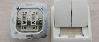
Two-key pass-through switch device
Any switch serves to break a phase wire and de-energize electrical appliances, but the specificity of a pass-through switch is that by opening one circuit, it closes the contacts of a paired switch.
Unlike a conventional device connected by two wires, a pass-through switch requires three-wire switching. At its core, it is a switch that directs voltage from one contact to another. The lighting turns on when the keys on both devices are in the same position and turns off when the position changes. Control can be carried out not only from two, but also from three or more places; for this, a cross switch is connected to the circuit, and if necessary, several. The single-key switch is equipped with three terminals. The two-key device has 5 terminals: two for connecting to switches and one common. The three-key switch has a more complex device, but if you have a diagram, it won’t be difficult to figure it out.
Installation of pass-through switch
Control circuit for pass-through switches
The connection diagram differs slightly from the installation of conventional switches, but the presence of three wires instead of two makes you think. Let's consider the purpose of each of them. Two wires are used as jumpers between switches located throughout the room, and the third is used to supply the phase. Before you start connecting the pass-through switch, buy a junction box in which the wires will be connected.
The ends of the wires are freed from insulation by 2-3 cm - this is necessary for twisting. If the wires are connected with connecting blocks, then the wire is stripped no more than 1 cm. In the distribution box, the wire supplying power from the distribution board is twisted with the input contact of the first switch. The two remaining output contacts are connected to the same wires from the second device. The input contact of the second switch is twisted with the wire from the lamp. The neutral wire from the lighting fixture is connected to the zero coming from the panel. All twist points are covered with insulating tape. The cross-section of wires for main switches is selected according to the power of the controlled lighting.
A device that controls two groups of luminaires
Connection diagram for two-key pass-through switches
It is advisable to install a two-key pass-through switch in a large room where it is necessary to control several lighting fixtures. Its design consists of two single switches in a common housing. Installing one device to control two groups allows you to save on laying cables to each of the single-key switches.
Installation of double pass-through switch
Such a device is used to turn on the light in the bathroom and toilet or in the corridor and on the landing; it is capable of turning on the light bulbs in a chandelier in several groups. To install a pass-through switch designed for two light bulbs, you will need more wires. Six wires are supplied to each, since, unlike a simple two-key switch, the pass-through switch does not have a common terminal. Essentially, these are two independent switches in one housing. The switching circuit for a switch with two keys is performed in the following sequence:
Cross Switch Connection
Two-key switches are also used when it is necessary to control lighting from three or four places. A double cross-type switch is installed between them. Its connection is provided by 8 wires, 4 for each limit switch. For complex connections with many wires, it is recommended to use junction boxes and label all cables. A standard Ø 60 mm box will not accommodate a large number of wires; you will need to increase the size of the product or install several paired ones or purchase a Ø 100 mm distribution box.
Wires in the junction box
It is important to remember that all work with electrical wiring and installation of devices is carried out with the voltage turned off.
This video describes the device, connection principle and installation of pass-through switches:
This video shows an experiment in which different methods of connecting wires were tested:
Wiring diagram
The principle of connecting pass-through switches
Connection diagram for a two-button switch with connection through a distribution box
Everything is written correctly in the article, but I came across the fact that the electrician who previously installed the switches did not leave spare wires in the box, and when one aluminum wire broke, he had to tinker with extending this wire. I advise you to leave a reserve for at least two repairs.
I myself studied to become an electrician and sometimes work part-time as an electrician. But every year, or even every month, more and more electrical questions are created. I work on private calls. But your published innovation is new to me. The scheme is interesting and will definitely be useful to me in the near future. I always try to take the advice of “experienced” electricians.
- Connection diagram for a two-button switch High-quality home repairs involve replacing electrical wires, sockets and switches. Many questions arise here...
- Connection diagram for a pass-through switch How many times have you had to feel your way out of a room along a dark corridor to turn on the light...
- Wiring diagram for a single-key switch School physics lessons, teachers and grades are a thing of the past, and electrical tasks are for men...
- Connection of a pass-through switch diagram from three places Connection diagram of a pass-through switch from 3 places: photo and video instructions For a certain configuration of premises (central…
Basic mistakes when connecting changeover equipment
- A common mistake when installing a pass-through device is incorrectly connecting the wires to the terminals;
- use of a cable with a small cross-section (it is recommended to use a 1.5 mm2 cable);
- It happens that when installing equipment, the wires are connected incorrectly (the phase must be connected to the contact of the first switch, and the second cable of the lighting device to the zero of the junction box);
- you need to be careful when selecting wires for switches (2 keys - three-wire, 3 keys - four-wire);
- Beginners make the mistake of thinking that the common terminal is the one that contains one contact. It is necessary to check the equipment with a tester screwdriver before connecting the cable.
When installing electrical wiring and installing structural elements, you must remember safety rules. Before starting work, it is important to turn off the voltage in the electrical panel. It is not recommended to touch the contacts with bare hands, even when the current is turned off; when installing devices, use only special tools.
Preparatory work before connection
In almost all cases, when installing two-key electrical installation products, additional wiring and installation of additional equipment will be required. And all this, most likely, will have to be purchased.
So, at the preparation stage you will need:
- Two three-wire wires of the required length for each switch. It is important that its cross-section is at least 2.5 mm². It is also important that copper is used as the manufacturing material. We recommend that you familiarize yourself with the rules for choosing wires for home wiring.
- Junction box . It is needed because the cable from the pass-through switch, for safety reasons, cannot be laid directly to the lighting fixtures. It should be remembered that there will be many connections, so the volume of one standard box is unlikely to be enough. Therefore, even before starting work, you should think about purchasing paired products.
- Installation box , which is also called a socket box. Such devices are used to accommodate the pass-through switches themselves.
The wire is laid in an open or closed way. But in any case, before starting installation, the purchased electrical cable should be checked for functionality.
The photo shows a model of the lighting control system, which allows you to get an idea of what should come out during the installation of two-key switches
When checking the cable, you first need to perform an external inspection, and then ring it using special equipment, for example, a multimeter.
If you ignore this rule, you can suffer significant losses. This is especially true for cases where the wire will be mounted into the wall.
If it is possible to ground the pass-through switch, then it should be used. This applies to cases where a PE bus is provided. It is usually available in new buildings.
When performing connection work, safety precautions must be observed. So, before starting the procedure, you should turn off the power to the room. .