SHARE ON SOCIAL NETWORKS
FacebookTwitterOkGoogle+PinterestVk
To increase comfort and convenience when operating lighting devices, a pass-through switch is used: the connection diagram clearly displays the operating principle of the switching device. With its help, you can control the lighting of the room from any point. The design features and installation rules of the product are described in detail in this article.
Pass-through switches are used to organize control of lamps from several places
Design and principle of operation of a pass-through switch
Pass-through switches are designed to turn lighting on and off from different ends of a room or flight of stairs. This means that you can turn on the light, for example, when entering a room, and turn it off in another part of it. This operating principle allows for significant energy savings.
Turning on lights from different places is not only very convenient, but also allows you to save quite a lot of energy
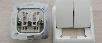
The pass-through switch does not differ in appearance from a regular one. Its front movable panel also shows up and down arrows. A typical switch has one input and one output. In contrast, a pass-through device has one input and two outputs. This indicates that the current is not interrupted here, but is redirected to any of the outputs.
Despite the fact that experienced electricians will be able to identify a pass-through switch by eye, reliable manufacturers produce products with a drawn electrical diagram of a double pass-through switch, triple or single, which is located under the device body.
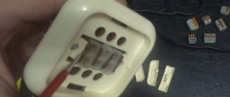
You can also determine that it is a single pass-through device before your eyes by examining the terminals with copper contacts. There should be three of them. To make sure that the terminals are not mixed up with each other, you should use a multimeter. The device should be put into beep mode and its input and output should be ringed. If the multimeter emits a signal when you touch a contact, there is a contact at that location.
Scheme of distribution of connections in the network
Another difference from a simple switch is that the pass-through device has three-wire switching, and not two-wire, like a regular one. This is a kind of switch that redirects voltage from one contact to another.
Pass-through switches usually work in pairs to control one light source. A zero and a phase are supplied to each. Changing the position of the switch key closes the circuit, which causes the light bulb to light up. When the first or second switch is turned off, the phase wiring opens, and the contact of the paired switch closes, and the light goes out. That is, when the keys on both devices are in the same position, the lighting turns on, in different ones it turns off.
You can control lighting not only from two places, but also from three or more. To do this, it is necessary to add one or more cross switches to the general circuit for connecting a pass-through switch from two places.
Lighting control from three places
Lighting control from three places
This connection method differs from previous options only in that a cross switch is added to the circuit. This device has 2 contacts at the input and a similar number of contacts at the output.
You have become familiar with the most popular installation schemes for pass-through switches. However, the number of such devices does not necessarily have to be limited to two or three. If necessary, the circuit can be expanded to include the required number of devices. The principle of operation remains the same for all cases: at the beginning and at the end of the circuit, a single pass-through switch with three contacts is installed, and cross devices with four contacts are used as intermediate elements.
We install switches to control lighting from three different places
If there are usually no problems with setting up a system to control lighting from two different places, because Since the circuit has a simple form, installing three switches can cause certain difficulties for an unprepared installer.
We will look at how to install a system of two pass-through and one crossover switches. By analogy, you can assemble a circuit from a larger number of devices.
Before carrying out any further work, turn off the power supply.
Turn off the electricity
To do this, find the corresponding switch in the in-house electrical panel or in the panel on the site (for apartment owners). Additionally, make sure that there is no voltage in the switch wires using a special indicator screwdriver. Also perform a similar check at the installation locations of the devices.
Scheme
Set for work
Set of tools
- Flathead and Phillips screwdrivers.
- Wire stripping tool. Can be replaced with a regular knife.
- Side cutters or pliers.
- Level.
- Indicator screwdriver.
- Hammer.
- Roulette.
Pass-through switches
Preparation of grooves and niches
To install switches, we must first prepare grooves in the wall for laying electrical cables, energize the wires and extend them to the locations of the installed devices.
Prices for Legrand switches
Legrand switch
Preparation of grooves and niches
To drill concrete walls, it is most convenient to use a hammer drill. If the partitions are made of limestone, it is better to make the indentations using a chisel, because In such material, the punch will leave a groove that is too wide and deep, which will make fixing the wire difficult and will require more cement or plaster consumption in the future.
Connection diagram for a pass-through switch for lighting control from 4 places
It is not recommended to use a hammer drill for chipping brick walls - it can split the masonry. In such a situation, the only safe solution is to lay the cables in pre-adapted joints between the masonry elements.
Wooden walls are not grooved - the wires are laid in special protective boxes. Most often, the cable is pulled under the baseboard and brought out directly under the switch installation site.
First step. We begin the work by connecting the wires to the electrical panel. There should not be any difficulties at this stage - modern devices allow you to connect up to 8 or more wires at once.
Expert opinion: Masalsky A.V.
Editor of the “construction” category on the Stroyday.ru portal. Specialist in engineering systems and drainage.
First you need to determine the optimal cable cross-section. Domestic power grids can hardly be called stable. The current strength in them constantly fluctuates, and in moments of overload it even increases to dangerous values. To avoid problems with wiring, we use copper wires with a cross-section of 2.5 mm2.
Second step. Select a convenient height for installing switches. At this point, we focus entirely on our preferences.
Third step. Having decided on the installation height of the switches, we proceed to gating. The width and depth of the grooves are 1.5 times larger than the diameter of the wire.
Important point! The wires are connected to the switches from below, so we install the groove 5-10 cm below the installation points of the switches. This requirement is relevant from a purely practical point of view, because in such conditions, working with cables is easier and more convenient.
Fourth step . We lay the wires in grooves. We fix the wiring elements with small nails. We drive nails into the wall so that they support the cable and prevent it from falling out. Before attaching the wires, we need to place them under the switch (installation box). We will consider this point in the main section of the instructions. We will plaster the grooves after installing all the switches, making sure that the system is working.
| Nom. current, A | Cable cross-section, mm2 | Permissible cable current, A | Cable outer diameter, mm |
| 16 | 2x1.5 | 20 | 13 |
| 16 | 3x1.5 | 18 | 13,6 |
| 40 | 2x2.5 | 27 | 14,6 |
| 40 | 3x4 | 32 | 17,6 |
| 63 | 1x10 | 75 | 13,2 |
| 63 | 2x10 | 60 | 21,6 |
| 63 | 3x16 | 70 | 24,9 |
| 100, 160 | 1x16 | 100 | 14,2 |
| 100, 160 | 2x25 | 100 | 27 |
| 100, 160 | 3x25 | 118 | 31,2 |
Fifth step. We make holes for installing switches according to the size of the devices used.
Let's move on to the main stage of work.
Installing switches
Connection diagram for two pass-through and one crossover switches
First step. We run the wires from the junction box under the switch. We cut the cables so that approximately 100 mm of their length remains in the installation box. Side cutters or pliers will help us with this. We remove approximately 1-1.5 cm of insulation from the ends of the wires.
Second step . Install the pass-through switch. We connect the phase cable (in our example it is white) to the terminal marked in the form of the letter L. We connect the remaining two cables to the terminals marked with arrows.
Installation of a pass-through switch
In your case, the color of the cables may vary. Don't know how to lay and connect the wires in the junction box? Then do the following. Turn off the electricity and find the phase. An indicator screwdriver will help you. A phase is a live cable. It is this that you connect to the terminal with the letter L, and the remaining wires are randomly connected to the terminals marked with arrows.
Third step . We install the cross switch. 4 wires are connected to it. We have a pair of cables, each of which has blue and white cores.
Connecting the cross switch
Let's understand the order of terminal markings on the switch. At the top we see a pair of arrows pointing “inside” the device, while at the bottom they are pointing “away” from it.
We connect the first pair of cables from the previously installed pass-through switch to the terminals at the top. We connect the remaining two cables to the terminals below.
To find live cables, we turn on the electricity and find the phases one by one. First, we determine the first one by changing the position of the key of the first pass-through switch. We find the next phase on the crossover switch cables. Next, we just have to connect the remaining wires to the terminals below.
Fourth step. Let's start connecting the last switch. We need to find the cables in it through which the voltage from the crossover switch flows. Our cables are blue and yellow. We connect them to the terminals marked with arrows. The white cable remains. We connect it to the terminal marked with the letter L.
Prices for two-key switches
two-gang switches
Let's move on to the last switch in the circuit
We already know the procedure for identifying live cables. In the case of the second switch, we need to connect a wire that will not have voltage to the L terminal.
Fifth step. Carefully insert the device mechanisms into the mounting boxes. We carefully bend the wires to the base. We secure the devices. Fasteners in the mounting box or “claws” for clamping mechanisms will help us with this.
Carefully install the switch mechanisms into the installation boxes
Sixth step. We attach the frame of each switch and secure it with the clasp from the kit.
We attach the frame of each switch and secure it with the clasp included in the kit.
Seventh step. We mount the switch keys.
Mounting switch keys
In conclusion, all we have to do is connect the lighting fixtures with the wires coming from the junction boxes, check the correct operation of the system and seal the strobes.
Good luck!
Advantages of installing a pass-through switch
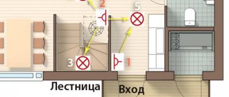
Pass-through switches allow you to control room lighting from two or more places, which is an undeniable convenience. This is especially valuable for multi-story houses with flights of stairs. Here you can install the first switch on the first floor and the next on the second, which will turn on the light downstairs and turn off the upstairs.
The use of walk-through switches for controlling the lighting of staircases is especially important.
A good solution is to install one switch at the entrance to the bedroom, and a second near the head of the bed, which will allow you to enter, turn on the light, get ready for bed, lie down and turn off the light. It is also advisable to install switches at the entrance to a house or apartment and at the end of the corridor.
Helpful advice! Using special motion sensors or a timer built into the switch, you can automatically turn off the lighting when leaving a certain place.
Walk-through switches have significant advantages compared to conventional devices:
- high reliability and safety of operation;
- instant shutdown of the power supply to the premises, if necessary, from any point;
- optimal energy consumption;
- low cost;
- simple installation that does not require the involvement of specialists;
- no complicated settings.
The presence of walk-through switches allows you to turn on the lamps below with one switch, and when going up the stairs, turn them off with another
How to disconnect a pass-through switch in a distribution box
To disconnect the cable and wire network, you must first install a distribution box. Next, all incoming cables can be connected using 3 main methods:
- Soldering
In this method, the 2 wires to be connected are pre-twisted, degreased with flux, tinned and soldered using rosin and tin. This method is considered the most time-consuming and if soldering is incorrect, there is a possibility that the contact between two conductors will be lost, which can damage the pass-through switch, lighting lamps, or in the worst case, cause a fire. However, if the soldering technology is followed, this method will ensure safe and durable operation of lighting circuits for decades. - Welding
Welding of wires is carried out using a step-down or welding transformer. The advantages of this method are high reliability, since 2 conductors are fused under the influence of high current, ensuring low connection resistance. - Installation of WAGO type terminal blocks
This type of connection of cable and wire products is the fastest, and the quality is in no way inferior to soldering and welding. The wires to be connected are simply inserted into the terminal block, after which the clamps snap into place and the cable is securely fastened into a special groove.
Important! When connecting wires in a junction box, it is forbidden to use ordinary twists, since over time, when electric current passes through the twist, the contact deteriorates and a short circuit may occur, followed by a fire. It is also prohibited to connect copper and aluminum wires without any gaskets made of other metals.
How to make a pass-through switch with your own hands
Despite the fact that at first glance, regular and pass-through switches have minor differences, their cost is significantly different. You can buy a pass-through switch 1.5-2 times more expensive than a simple switch. Therefore, many craftsmen strive to make a switching device themselves.
To get a pass-through single-key switch, you need to use conventional single-key and two-key devices of the same size and manufacturer.
Helpful advice! When purchasing a two-key pass-through switch, the diagram of which is printed on the body of the device, you should make sure that it has the ability to move the terminals in places in such an order as to ensure that the circuit is broken and closed independently of each other.
The process of converting a simple switch into a walk-through switch consists of the following steps:
- on a surface-mounted single-key switch, the key equipped with clips is removed;
- the switch core is carefully squeezed out;
- the housing clamps on the internal mechanism of the switch are pressed out;
- one of the terminals is removed from the socket;
- one contact is reinstalled opposite the other;
- a rocker arm is installed on the contacts;
- the body is put back together.
Using pass-through switches will be convenient if the house has long corridors
You can also assemble one switch from two simple ones. They should be placed next to each other so that when the top part of the key is pressed, one is activated, and the bottom – the other. The keys should be connected with a plate that is glued on top. It is imperative to install a jumper between two adjacent contacts.
Features and design of a two-key switch
There are a huge number of switches equipped with two keys, but in practice this is not the only criterion. Since similar features are inherent in some types of pass-through and crossover switches. Therefore, in order not to get confused in such devices, it is necessary to understand in detail their design and functional features.
The main task of a two-key switch is to divide the supply conductor into two independent lines, switched by two separate keys. Therefore, when you connect the device, you will find three pins on the back, as shown in Figure 1 below:
Rice. 1. Features of two-key switch
The three clamps are for:
- 1 – transmission of electricity to the first group of lighting equipment;
- 2 – transmission of electricity to the second group of lighting equipment;
- L – used to connect the phase conductor from the electrical wiring;
On the switch body itself there is also a diagram of a two-key switch, which shows the principle of operation and switching of contacts.
Rice. 2. Two-key switch design
Structurally, a two-key switch consists of the following elements:
- Keys – designed for manual control of the switching process. In accordance with clause 10.2 of GOST R 51324.1-2012, they are made of insulating material to prevent contact of human hands with live parts.
- Contact group switch - moves the switch contacts to the on or off position. Each switch in a particular model is designed to allow direct connection to a key.
- The switch module is the main block of the switch, containing the contact group and the mechanism that sets them in motion.
- Latch – in this model it is made as a separate part and is used to fasten the false panel to the switch module. It can also be made in the form of locks on a module or false panels, as their integral part.
- False panel - used for decorative decoration of the switch. Can be selected according to color for interior design.
Some models may be equipped with a light indication of the off state. An LED is installed inside the switch keys themselves or in the false panel, which lights up in the off position. This option makes it easier to detect a two-key device in the dark, but makes its own adjustments when using LED and fluorescent lamps.
Connection diagram for a pass-through switch with 2 places
The circuit of a pass-through switch from two places is carried out using two pass-through single-key devices that work only in pairs. Each of them has one contact at the entry point, and a pair at the exit point.
Before connecting the pass-through switch, the connection diagram clearly displays all the stages; you should de-energize the room using the appropriate switch located in the control panel. After which it is necessary to additionally check that there is no voltage in all wires of the switch. To do this, use a special screwdriver.
Helpful advice! A similar check must be performed at the installation sites of switching devices.
To complete the work you will need: flat-head, Phillips and indicator screwdrivers, a knife, side cutters, a level, a tape measure and a hammer drill. To install switches and lay wires in the walls of the room, appropriate holes and grooves must be made in accordance with the device layout plan.
Unlike conventional switches, pass-through switches have not two, but three contacts and can switch the “phase” from the first contact to the second or third
Important! It is impossible to install a pass-through switch in place of a simple switch.
Wires must be laid at a distance of at least 15 cm from the ceiling. They can be placed not only in a hidden way, but also placed in trays or boxes. This installation makes it possible to quickly carry out repair work in case of cable damage. The ends of the wires must be inserted into installation boxes, in which all connections are also made using contactors.
Procedure for installing pass-through switches at 2 points: connection diagram
All actions for installing switching devices are carried out on the basis of a connection diagram of 2 places of pass-through switches, which can be found on the Internet. It differs from the installation of conventional switches, since there are three wires instead of the usual two. In this case, two wires are used as a jumper between two switches located in different places in the room, and the third is used to supply the phase.
Any type of lamp can be used as a lighting source in such a scheme - from conventional incandescent lamps to fluorescent, energy-saving and LED
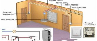
Five wires must be suitable for the distribution box: power supply from the machine, three cables going to the switches, and a connected wire directed to the lighting fixture. When constructing a connection diagram for a single-key pass-through switch, three-core cables are used. The “zero” and grounding wires are led directly to the light source. The brown phase wire, which supplies current, passes through the switches, according to the diagram, and is output to the lighting lamp.
Helpful advice! To avoid problems with future wiring, it is recommended to use copper wires with a cross-section of at least 2.5 mm2.
The switches are connected at the break in the phase wire, and the zero, having passed through the distribution box, is directed to the lighting fixture. Passing a phase through the switch will ensure safety during repair and maintenance of the lamp.
Installation of a pass-through switch consists of the following sequence of actions:
- the ends of the wires are stripped of insulation;
- using an indicator it is necessary to determine the phase wire;
- using twisting, the phase wire should be connected to one of the wires on the first switch (white or red wires are used here);
- the zero terminals of the switches are connected by wires;
- connecting a separate wire of the second switch to the lamp;
- in the junction box the wire from the lamp is connected to the neutral wire;
When installing pass-through switches yourself, you need to take care of safety precautions
Helpful advice! If twists are made, they should be soldered and wrapped with electrical tape.
General provisions
Next, we will consider the most common schemes for powering the lighting elements of a room.
The features of creating such branches largely depend on the number of lamps connected to them, as well as their control using a switch.
But in any case, the created branch includes:
- Switch (one-, two-, three-key);
- Lamps with sockets;
- Junction box;
- Wires (two- and three-core).
A little about the features of the breaker.
Any switch has two outputs - input and output (there may be several of the latter).
Moreover, both of them belong to the same line, that is, if a phase is connected to the input terminal, then it will also be at the output.
By moving the key to a certain position, the contacts of these terminals are connected or disconnected, thereby closing or opening the circuit.
Safety precautions.
Before describing connection methods, let us immediately remind you of safety precautions when carrying out work.
To avoid electric shock, turn off the power supply and take steps to prevent accidental restoration of power before work is completed.
Its supply should be restored only after complete installation and connection of all components of the branch, as well as ensuring reliable insulation of the wire connection points.
Read on: is it worth using aluminum wiring?
Pass-through switch: connection diagram from three or more places
If there is a need to control lighting fixtures from different places, then you should implement a 3-point pass-through switch connection diagram. This is true for multi-story buildings, large halls, long corridors with several exits. To do this, you will need, in addition to the two conventional pass-through switches, a cross switch. In such a switching device there are not three, but four contacts: one pair of input and two output, which switch simultaneously. To do this, use a four-core cable.
Connection diagram for three pass-through switches
In the connection diagram for pass-through switches from 3 places, conventional switches are used at the first and last point, between which a cross switch is installed.
Helpful advice! Since wiring in the distribution box with each additional point involves a large number of wires, it is recommended to label the wires.
The connection diagram for pass-through switches from three places will look like this:
- “zero” and grounding are output to the lamp;
- connecting the phase to the input of the first pass-through switch;
- using wires, the output contacts of the first switch are connected to the input pair of crossover switch terminals;
- connecting the output wires of the crossover switch to a pair of terminals at the output of the second pass-through switch;
- the wire from the second switch is supplied to the lamp;
- the second wire, which comes from the lamp, comes to the junction box at “zero”.
Related article:
Socket: how to connect electrical fittings without the help of a specialist
How to connect an outlet with your own hands. Description of preparatory activities and installation technology. Rules for handling the electrical network
If lighting control is planned from a larger number of places, additional cross-switches are introduced into the overall circuit, which are connected according to the above principle.
A three-wire cable is supplied to each pass-through switch, and a four-wire cable is supplied to the crossover switch. All wires used for connection must be of the same cross-section. Switches that can operate at normal currents of 6.10 and 16A must have the same rating. A visual diagram for connecting pass-through switches from 3 places can be seen on specialized websites on the Internet.
The procedure for connecting a pass-through switch is not much different from connecting a conventional switch
Circuit for controlling lighting from two places
This circuit is designed to control lighting from two places.
The system is assembled from two single-type pass-through switches.
Each of these devices has one contact at the input and a pair of contacts at the output.
Prices for pass-through switch
pass-through switch
It uses 2 single-type pass-through switches
Switch
The “zero” wire is connected from the power source through the distribution box to the lighting fixture. The phase cable, also passing through the box, is connected to the common contact of the first switch. The output contacts of this switch are connected via a box to the output contacts of the next device.
Circuit for controlling lighting from two places
Finally, the wire from the common contact of the 2nd switch is connected to the lighting fixture via a junction box.
Connection diagram for a two-key pass-through switch
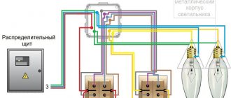
Using pass-through switches, you can control not only one lamp, but also a group of several lighting fixtures. To do this, connect pass-through two-key switches. Each of them has six contacts. Common wires are determined according to the same principle as for conventional devices, but a larger number of wires need to be wired.
The difference between the double pass-through switch wiring diagram is that more wires are used here. The phase is supplied to both inputs of the first switch. Wires should go out from the two inputs of the second switch to two lamps. In the case of organizing lighting control from three or more points, two cross switches should be installed for each of them, since they are only available as single-key switches.
Connection diagram for a pass-through two-key switch
In this case, according to the principle of connecting double pass-through switches with crossover switches, the first pair of contacts should be connected to one crossover, and the second to the other. If necessary, the devices are connected to each other. The output of both crossover switches must be connected to the last two-key transfer device.
Touch switch models
In addition to keyboard and lever modifications, there are touch-sensitive models on the market. In essence, the functions of the devices are the same, but the principle of operation, as well as the design, are somewhat different.
The modern modification is a touch model, which has a more convenient operating principle. In addition, this type of household communicators has an increased service life due to the absence of mechanics in the design
There are two types of touch switches:
- Direct sensors.
- Touch sensors with dimmers.
The first ones work on direct, clear contact through a brief touch of the fingertip to the glass panel of the device. That is, in this option only the on/off function works. The second design option (dimmer) provides switching on and off with smooth control of the brightness of the lamps.
To work with these devices, the same finger touch is required, followed by holding the fingertip on the glass until the required brightness of the lamp is achieved.
Rear view of the touch device, where the connection terminals are located: COM – synchronizing connector for working in pairs with other devices; L – contact for the network phase; L1 – first output channel; L2 – second output channel
The circuitry of sensor devices differs from devices of other designs in that it contains one common (phase) terminal (L), two changeover terminals (L1, L2) and one “COM” terminal.
The "COM" contact is used for communication between switches when building complex circuits. For example, with control of several lighting zones from three or more points. In this case, a load power of no more than 1 kW is allowed per light zone.
The classic version of circuit wiring with one sensor device: N – electrical zero; L – electrical phase; L1 – load of the first channel; L2 – load of the second channel
A simple organization of a control system with one sensor device is performed as follows:
- The phase line is connected to the “L” terminal.
- Line "L1" forms one lighting zone.
- Line "L2" forms the second lighting zone.
If a group of devices is used, the phase contacts of the devices (L) are connected in parallel, plus the “COM” terminals are connected to each other. All other terminals are connected as standard depending on the number of switched light zones.
In order for touch devices to function correctly, they must be programmed. Essentially, we are talking about synchronizing all switches in a group. Programming is performed in the following sequence:
- Touch the sensor for 5 seconds. until a beep sounds (or the LED blinks).
- After the beep, release the touch and move on to the next device.
- Touching the sensor of the second device.
- If the LED on the front panel responds with short flashes, success.
- Cancel synchronization - touch the sensor for 10 seconds.
For touch structures there are some installation restrictions.
For example, the maximum permissible distance from switch to switch must be at least 30 m.
We also recommend reading our other article, where we talked in detail about touch-sensitive light switches, their types and markings.
Well-known manufacturers of pass-through switches
The Legrand company occupies a leading position in the electrical goods market. The demand for Legrand pass-through switches is due to the high quality of the products, ease of installation, ease of further operation, stylish design and flexible pricing policy. The only drawback is the need to adjust the installation location. If it does not coincide with the product, difficulties may arise during its installation, which is carried out according to the connection diagram for the Legrand pass-through switch.
Legrand pass-through switches
A subsidiary of Legrand is the Chinese company Lezard. However, the products have only a stylish design left from their native brand. The build quality is much lower, which is due to the low cost of the products.
One of the leading domestic manufacturers of electrical goods is the Wessen company, which is part of the Schneider Electric company. All products are manufactured using the latest technologies on modern foreign equipment and comply with European quality standards. The models have a universal, stylish design that allows each element to fit into any interior of the room. A distinctive feature of Wessen switches is the ability to replace the decorative frame without dismantling the device.
Another equally well-known manufacturer is the Turkish company Viko. The products are characterized by high quality workmanship, reliability and durability, and comply with electrical safety requirements and European quality standards. In the manufacture of the device body, fireproof durable plastic is used, which is designed for a large number of operating cycles.
A pass-through switch, unlike a regular switch, has three conductive wires
The Turkish brand Makel offers high-quality, reliable, safe and stylish products. Thanks to the ability to connect a cable without the need to use a distribution box, installation of switches becomes simpler, and further operation becomes comfortable and safe.
Three-point lighting control option
If there is a need for remote control of the lamp from three places, then you will also have to purchase a cross switch. It switches not one, but two contacts at a time, so it has two inputs and two outputs.
How to connect all three switches can be seen in the figure. This is somewhat more complicated than the previous case, but you can understand the principle of operation.
Electrical diagram for switching on a lamp from three places.
To connect an electric light source, according to this diagram, you must perform the following operations:
- The neutral wire is connected to one of the lamp wires.
- The phase wire is connected to the input contact of one of the pass-through switches.
- The free wire of the lamp is connected to the input contact of the second switch (pass-through).
- The two output contacts of the pass-through switch are connected to the two input contacts of the crossover switch.
- The two output contacts of the second pass-through switch are connected to the two output contacts of the crossover switch.
The diagram is the same, but it is shown more clearly where exactly to connect the wires.
Which terminals are the wires connected to?
This is approximately how you should route the wires around the room.
Based on a circuit for three control points, you can assemble circuits for 4 or 5 points. In such cases, it is necessary to increase the number of crossover switches. They should always be installed between two pass-through switches.
Scheme of organizing on/off lamp for 5 points.
If you remove one of the cross switches from this circuit, you get a 4-point option, and if you add one cross switch to it, you get a 6-point option.
Pass-through switches from 5 places without junction boxes. Suneler.ru
Principle of operation
Walk-through switches are no different in appearance from conventional key switches - their design and principle of operation have their own specifics. The main differences between these switching devices are the number and order of connection of the switching contacts.
Please note: When a conventional single light switch is triggered, the phase circuit in which the switching device is connected is simply closed or opened.
When operating 2-pass switches, the order of breaking and closing the chain supplying phase voltage to the lighting device is more complex and branched. During the switching process, two such switches, the diagram of which is discussed below, close one of the connecting lines while simultaneously opening the other.
Due to this, it is possible to implement the principle of separate control of the same lighting device from two places located at a considerable distance from one another. The most typical example of such an organization is the location of switches at opposite ends of a long corridor. This feature ultimately determines the specifics of installation of walk-through switches within the boundaries of a particular inhabited room.
conclusions
When analyzing all the connection diagrams for pass-through switches discussed in this review, the following can be noted:
- The simplest of these systems provide undeniable advantages and do not have any noticeable disadvantages (this applies to a pass-through switch with one key, in particular).
- More complex complexes, which also include crossover devices, may not be as effective as they seem.
- This is explained by the fact that even taking into account the ease of management, their use is associated with high costs and a decrease in the reliability of the entire system as a whole.
- When installing switching circuits in which switches are arranged in a daisy chain, you will need to carefully monitor the order of switching in order to prevent critical errors.
- This should also be attributed to the disadvantages of complex kits that include crossover switches.
In the final part of the review, we note that when arranging such systems one has to deal with certain difficulties in laying linear conductors. When choosing an installation method, there are options for hiding them deep in the walls or using special cable channels for this. If the owner of a private house plans to “hide” the wires deep into the walls, he should worry about this in advance (preferably at the stage of developing the construction project).