Switch device
The design of the device is divided into two parts:
- Plastic frame with keys (protective part).
- Working mechanism (working part, wires).
In different models, the fastening of the frame is not the same - it can be fixed with two screws or latches. In the latter case, the latches are easy to connect and disconnect with the movement of your fingers.
There are also two options for mounting the working part in the mounting box (glass, socket box). This is done by fixing a metal frame with holes, allowing the mechanism inside the glass to be widely adjusted, or by using spacer tabs. There are two screws on the sides of the mechanism, when tightened, the legs unfold until they fit snugly into the socket box.
To correctly connect a double switch to two light bulbs, you need to study the wires and contacts present in advance. The latter are needed for connection with suitable wires and outgoing cables.
According to the type of design for fixing wires, switches can be:
- with self-clamping contacts - the wires are secured with springs;
- with screw contacts - the wires are fixed with plates with screws.
All switches with two keys have at least three contacts - an input and two outputs. The phase wire must be connected to the common input, the output wires must be connected to different sections of the lighting points.
How to choose a circuit for two light bulbs
There are differences in the connection of 1-key and 2-key switches. To better understand the difference, let's first look at the installation nuances of a single-keyboard player.
You can connect one or more light bulbs to a regular switch with a single key - the principle remains the same.
The diagram shows an option using a two-core cable, without using ground. The neutral core is pulled directly to the lighting fixture, and the phase is connected to the switch, from where it goes to the light bulbs (+)
This is the simplest scheme; it is traditionally used if simple control of a lamp or an entire group is needed. When the electrical installation is turned on, all involved light sources light up. If there is a chandelier or sconce with two lamps, then both will turn on at once; it will not be possible to use them one at a time.
Now let’s look at what changes if a single-key device is replaced with a two-key device. The first circuit for connecting a double switch to two separate light bulbs is relevant for the TN-C system, which is still found in old houses. For the lighting circuit, two-core wires are used.
The zero is sent through the junction box directly to the lamps connected in series, and the phase goes to the input terminal of the switch. But the output is already double: a phase conductor goes from each of the output terminals to a separate lamp (+)
It turns out that you can use either one or both light bulbs at the same time, using either one or two keys.
A positive point is the ability to change the lighting intensity in one room. If the lamps are in different rooms, then you can turn on the lights in each room separately or in both at once.
In new houses, grounding systems that differ in design are used, for example, TN-S. The difference between the second scheme for a home electrical network is that a three-wire wire is required: the third wire is the “ground”.
Like the neutral conductor, the grounding conductor is sent to the distribution box, and then connected to the wires of the lamps and connected to metal parts (+)
The grounding wire is connected differently if there is an outlet in the same block as the switch. Then the “ground” from the electrical panel reaches to the distribution box, and from there to the outlet.
Preparatory work
When working with electrical equipment, extreme precision and caution must be observed, therefore all materials and tools needed for the work must be prepared and purchased in advance:
- flat and Phillips screwdriver;
- pliers;
- side cutters;
- insulating tape;
- a good construction knife with a sharp blade (for stripping wire ends);
- for crimping it is more convenient to use a special tool - a crimper (it is not necessary if the wires are not stranded);
- switch;
- wires.
Attention! It is very important to turn off the power supply before starting work!
It is extremely important (especially for non-professionals) to correctly draw the connection diagram and lay out the wiring in advance.
The circuit should include the following three wires:
- Ground wire (exited to the light source, indicated on the diagram as “0” or with an arrow pointing down).
- Neutral wire (also led to the light source, designated by the letter “N”).
- Phase is a live wire that, when turned on, should provide power to the light bulbs (the terminals for the phase wire are designated by the Latin letter “L”).
You can install the wiring in one of two possible ways: open or closed. For the first, you will need additional materials - corrugated pipes or grooves, for the second - you need to cut grooves in the walls.
Please note that wiring is done before plastering the walls and ceiling. This means that only after all the wires have been laid and are sufficiently insulated, you can begin finishing work.
To make a small recess under the switch, you will also have to use a chisel and a hammer (this is not necessary if the switch will be installed in the old place).
What is an RCD in electrical engineering: types, principle of operation
How to connect a pass-through switch: connection diagrams
Practical recommendations and advice
If you adhere to a set of simple rules, then this kind of installation work will not be dangerous, which is especially important for closed type networks.
Remember that any work with electricity should be carried out only after the apartment or house has been completely de-energized at the main panel. Before any wiring problem, make sure that there is no voltage on the phase. When dismantling a two-key switch and installing a dimmer or non-contact type switch, study the connection diagram in detail - they differ in each case.
Installing electrical switches and wiring in premises does not always require the involvement of a qualified specialist, however, it is always worth remembering the rules of safe work with electricity, taking into account key factors, and based on this, you can choose the right connection diagram specifically for your types of lamps.
Installation of a two-button light switch and connecting wires
There is nothing complicated in the connection diagram and in the process of installation, installation and connection of wires to the switch contacts. First of all, the switch needs to be disassembled. To do this, remove the keys themselves. If you can’t do this manually by simply pulling them towards you, use an ordinary screwdriver, prying the keys off from the side. Next comes the insulating decorative backing; it can either be snap-on or screwed on. Remove this frame.
As a result, what you have in your hands is the body itself with the fastenings on the sides and the internal contact part. The main task is to supply voltage from the phase conductor to the common contact. Further, when two keys are closed, this phase will diverge into one or the other lighting circuit.
To find the central contact, look at the marking, since it may not always be located alone and along src=”https://electric-220.ru/images/wp-content/uploads/2017/02/kont_verh.jpg” class =”aligncenter” width=”596″ height=”600″[/img]
What to do if you don’t understand the inscriptions or they are erased and painted over? Then you need to use a contact screwdriver with a battery-powered tester with a continuity test function. Insert any metal object (nail, screw) into the supposed common contact. You wrap your fingers around it and touch the other two contacts with a screwdriver.
When you press the keys one by one, that is, turn on one - check, then turn off the first and turn on the second - check, the screwdriver LED should light up each time. If this does not happen, then this is not a common contact.
When you have dealt with the contact part of the switch, take the three-core cable VVGng 3*1.5. It is desirable that the colors of the cable cores correspond to the color markings according to GOST. How to determine by color which conductor should be phase and which should be neutral by reading the article “How to distinguish wires by color.”
To connect the common contact, use the gray conductor phase coming from the junction box. Strip the end of the core, insert it between the contact plates and tighten the screw with a screwdriver.
Next, connect the other two wires in the cable to the outgoing contact connectors.
Connecting the conductors directly to the two-key switch itself is now complete. Insert the housing into the mounting box and tighten the mounting screws.
Then you tighten two spacer screws, which help the mounting fork with teeth to rest as much as possible against the walls of the box and firmly hold the switch body inside it.
After this, you can return all the decorative frames and the keys themselves to their place.
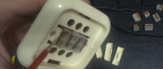
Device design with two keys
True to its name, the two-key device from the front looks like an electrical device, on the front panel of which there are two plastic buttons enclosed in a decorative frame. If the plastic parts are removed, you can see two movable panels that move the contacts.
Double with plastic parts removed.
If you continue to disassemble the device further, you can see the contact group and a visual diagram of its connection.
Contact group with two pairs of contacts.
The electrical circuit of the twin consists of two switches. Their inputs are combined and connected to a common terminal.
Electrical circuit diagram.
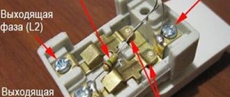
These terminals can be seen on the back of the device:
- general (it is often designated by the letter L; in the same way, in many cases, the wire that is connected to this terminal is marked);
- two outgoing (L1 and L2), respectively, these terminals are equivalent and are each controlled by its own key.
View from the back.
Some devices are equipped with a backlight chain. It is performed on the basis of an LED or neon lamp.
Backlight circuit diagram.
In most cases, the backlight circuit is placed on only one pair of contacts. This must be taken into account, for example, when looking for reasons for blinking LED lamps.
View of the device with backlight.
Double switch connection diagrams
Before starting installation, it is necessary to divide the spotlights or chandelier bulbs that are planned to be connected to one DV into two groups. To create different lighting modes, they must be unequal (for example, 2 + 6 or 1 + 2).
More than two groups cannot be connected to one two-key switch; for a similar purpose, a three-key switch or separate electromechanical devices are used.
Using the simplest connection diagram, you can correctly distribute the wires. But first you need to study the color and alphanumeric designations, so that in the future it will be easier to “communicate” with the diagrams (+)
Precautions when connecting a chandelier
The first thing you need to do before connecting the chandelier is to turn off the power to the entire apartment or house - turn off the input circuit breaker. It is necessary to disassemble switches, open distribution boxes, and connect a chandelier only when there is no voltage.
Having disconnected the input circuit breaker, you need to check with a voltage indicator that there is no phase at the output terminals of the input circuit breaker and in the sockets.
Before calling phase wires on the ceiling, switch, distribution box, you need to prepare them, remove the insulation from the wires and move them apart.
Next, you need to turn off the input circuit breaker and identify the phase and neutral wires with a voltage indicator and remember them. After turning off the input circuit breaker, mark the phase wires so that when connecting the chandelier you do not forget their location.
For safety reasons, when replacing lamps on a chandelier, all phase wires are connected to the central contact of the lamp socket. Therefore, all the wires of the central contact of the cartridges are ringed with a tester and collected in groups for connection to a double switch, the remaining neutral wires are collected together on the chandelier terminal block or twisted.
Step-by-step installation instructions
Theoretically, the process of connecting a switching device can be divided into several main stages. Installation must begin with the cables. So, if the wiring is old enough, then it must be replaced with a new one. After this, you need to make the correct connection of the wires in the junction box, and then in the switch itself. To install a lamp or chandelier, you must use the manufacturer's instructions, specially designed for a particular light source.
Carrying out preparatory work
First of all, what needs to be done is to arrange a “nest” for mounting the cup holder. At the same time, in accordance with the diagram of the two-key switch and its intended purpose, the walls are tapped. There is one phase, which means one two-core cord stretches from the distribution box, while after the switch there can be two of them if you need to organize two independent, free-standing lighting fixtures.
The work will not be completed without:
- Perforator with drill. This is an alloy tip that can drill through concrete or brick.
- Drills, jigsaws, which do an excellent job with drywall.
- Single-pole circuit breaker with a residual current device (RCD) to ensure the safety of consumers and users.
- The switch itself, equipped with two keys that open the circuits respectively.
- Switch boxes and a pre-purchased chandelier or two individual light sources.
- The socket box, also known as the cup holder, is a casing that protects the insides of the switch.
- Electrical cables of sufficient size to withstand the design load of energy consumption.
- Insulating tape and specialized fasteners that ensure a safe, reliable connection of wires.
- Screwdrivers (phillips or figured, flat) with insulated handles made of plastic, rubber, polyurethane.
- Knife (stationery, shoemaker), wire cutters, pliers, the handles of which are also made of insulator.
When a two-gang switch is used, the connection involves installing a junction box and laying a power cable. The system is first de-energized at the input. And on the switch there is a sign “Do not turn on! Work is underway."
Installation is carried out after the plaster, primer, and wallpaper glue have completely dried. The RCD and the machine are installed at the “entrance”. Their task is to respond to a power surge or network overload, and promptly turn off consumption points if this happens. Then a short circuit is excluded.
When installing a two-button switch, protective devices are mounted in the switchboard. In its absence - on a wooden, plastic, textolite strip in the apartment after the meter.
Preparing the walls
The wall gating stage is very important and should only be skipped if new wiring with copper conductors of a suitable cross-section is installed. If there are any doubts, it is better to consult a specialist. If the wiring is old, be sure to replace it with a new one.
For lighting purposes, the most ordinary VVGng wire is suitable, the cross-section of which is 1.5 mm² square. If, along with lighting, sockets will be connected, then it is better to give preference to the same wire, but with a cross-section of 2.5 mm².
At the stage of preparing the walls, grooves and arrangement should be carried out, preparation of places where the installation of distribution boxes and socket boxes will be carried out. At this stage, experts also recommend installing an additional circuit breaker in the electrical panel. This separate device will not be superfluous, especially in situations where repairs are required on the lighting line. Using such a simple protective device, it will be possible to turn off only one circuit, while the rest will continue to operate in standard mode.
It is worth noting that in the case of wooden houses the type of wiring is significantly different, so a hidden installation method is not used, since this additionally increases the level of fire danger. In this regard, cables must be insulated as much as possible.
Wires are installed from the outside using special insulators. In this case, not internal, but surface-mounted switches are installed, however, the basic principle of connecting the cores to the terminals remains the same.
Labor protection rules when performing electrical installation
To ensure safety when working in an electrical installation, work must be carried out with the voltage removed. To do this, connect the lighting system to the circuit breaker last.
The switchboard is considered an active electrical installation, therefore, when working in it, several technical measures must be taken:
- turn off the group (input) switch;
- temporarily connect the power bus of the machines to the PE conductor (if available);
- check that there is no voltage on the power bus.
Perform all work wearing dielectric gloves and insulated hand tools. Safety regulations also require the use of dielectric mats.
Clear step-by-step video: Connecting the switch during repairs.
Useful tips
- Calculate in advance the required (sufficient) cross-section and length of the wires depending on the power of the light sources. The cross-section cannot be less than one and a half square millimeters.
- In addition to the distribution box, it is also recommended to purchase an additional protective device that will protect against short circuits and overloads in the electrical network.
- Choose terminal switches rather than those with screw-in screws, as the first connection option is stronger and more durable: the screws will need to be tightened after a while.
- You can adjust the lighting using a single-key device! But for this, additional equipment is purchased and installed - the so-called dimmer.
- If you install a similar structure to illuminate a bathroom or other damp place, do not mount the switch indoors under any circumstances.
- Note: if the switch is modular, then there is always another one near the input terminal. These two terminals must be connected to each other with a separate wire.
- All connections and connections are strictly prohibited outside special junction boxes. And in the case of complicated environmental conditions, additional protection must be made (for example, from water, humidity, ingress of other solid and liquid substances).
- If you install a switch, for example, for a toilet, then one of the keys can turn on the light in this room, and the other can turn on the hood.
Connecting a switch that controls the light with two keys is not difficult if you strictly follow the instructions given above. Read all the instructions and useful tips first so that you don’t miss anything, then everything will work out!
Display useful videos on the topic
From the above it can be seen that connecting a two-button light switch is not difficult. And anyone can do the work, especially since this requires a minimum set of tools. However, there are a lot of subtleties that are difficult to convey in words, and a master class from a professional electrician will eliminate the knowledge gap and lack of skills. Pause the video and everything will be done together with an electrician. Then there will be no mistakes, and your home will be illuminated. By the way, the video shows the difference between installing a cup holder in walls made of different materials. Various switch designs, types of connections, wiring features, etc. are considered
Corridor lighting scheme using two pass-through switches
Externally, pass-through switches are almost no different from ordinary ones. Only on the reverse side there are three terminals instead of two:
- phase;
- L#1;
- L#2;
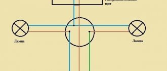
How to connect a lamp to two switches correctly is shown in the diagram.
“Zero” is supplied to the lamp via the blue wire. Phase - in red. The figure clearly shows that power will be supplied to the lamp only if both switches are in the same positions. Changing the position of the key on any device will break the circuit and cut off power to the lighting device. Well, after the light is turned off, clicking any of the switches will close the circuit again, and our corridor will be illuminated again.
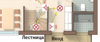
In staircases, long corridors or tunnels, instead of expensive infrared sensors, you can simply connect two pass-through switches.
Two independent switches for 2 lamps
This solution is quite rare, although double switches often have 4 terminals. That is, sometimes a double switch consists of two independent separate switches. Or you just have 2 single rocker switches. Then we simply divide the switch in the diagram into two halves, each of which is placed where it is needed in the room.
This allows you to connect each lamp to its own power source.
We are sure that after studying this article, connecting a double switch will be as simple as connecting a pass-through switch.