A diode is a popular element used in electrical engineering and serves as a light indicator. For it to work properly and emit light, it must be connected correctly, with correct polarity. You can determine it in several ways: using a multimeter, a regular battery or a power supply from a mobile phone. There are several more options for locating the cathode and anode of the diode. However, unlike the previously mentioned methods, they do not provide a 100% guarantee of accurate results.
Determining the polarity of the anode and cathode in an LED Source userapi.com
Why you need to be able to distinguish an anode from a cathode
Determining the “plus” and “minus” of the LED is necessary to check the existing icon where it is missing. This often happens on new, “used” diodes soldered from old circuits. In this case, there is no guarantee that the manufacturer of cheap elements did not make a mistake in their labeling. Therefore, there is no guarantee of compliance with the existing markings.
Connection without preliminary testing may result in the LED being broken and the electrical circuit not working. This will happen due to the fact that the diode current moves in one direction (except for two-color LEDs, blinking LEDs or IR). Only correct wiring will allow you to get a normal, working electrical circuit.
Important! Precisely determining where the anode and cathode are on a diode allows you to assemble the correct electrical circuits and eliminate the possibility of LED breakdown or LED blinking.
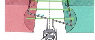
Rectifier diode connection circuit
The simplest rectifier works according to the following scheme. The input is supplied with alternating mains voltage with positive and negative half-cycles, colored red and blue, respectively. A normal load RH is connected at the output, and a diode VD will be the rectifying element.
When positive half-cycles of voltage are applied to the anode, the diode opens. During this period, direct diode current Ipr will flow through the diode and the load powered from the rectifier. On the chart on the right, this wave is indicated in red.
Expert opinion
It-Technology, Electrical power and electronics specialist
Ask questions to the “Specialist for modernization of energy generation systems”
Circuit of a simple AC rectifier using one diode. Note that it is not at all necessary to use four rectifying semiconductor elements; it is enough to take a ready-made assembly in a plastic case. Ask, I'm in touch!
Types of diodes
LED elements are divided into 2 volumetric types: semiconductor and non-semiconductor. The device of the first involves a small container with pumped out air and two electrodes inside:
- Plus, having electrical conductivity P.
- Minus, which has electrical conductivity N.
Anode and cathode in an LED Source multiurok.ru
Non-semiconductor diodes are in turn divided into 2 more groups:
- Vacuum (kenotrons), built on the principle of a lamp having 2 electrodes, where one of them is represented as an incandescent filament. In the slightly open position, the movement of electrons is from the pole to the minus. In the closed position, the movement path changes in the opposite direction or is suspended.
- Filled with gas (zener diodes with a smoldering or corona charge of ignitrons and gastrons). Of the voluminous list of elements, the most popular are gastrons with an arc charge (zener diodes). An inert gas is pumped inside them and oxide thermal cathodes are placed. The key feature of such LEDs is the ability to produce high output voltage and the ability to operate with voltage, the value of which can reach several tens of amperes.
Important! The value of resistance in the closed position is directly related to the value of forward current. If it is high, then the resistance will be low.
What is a semiconductor diode - AC rectifier
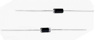
Diodes are two-electrode devices that have one-way conductivity of electric current. This main property is used, for example, in rectifiers, where diodes convert alternating current from the mains into direct current to power radio equipment, in receivers - to detect modulated high-frequency oscillations, that is, convert them into low (sound) frequency oscillations.
A clear illustration of this property of a diode can be the following experiment (Fig. 12). In a circuit made up of a 3336L battery and a light bulb from a flashlight (3.5 V X 0.26 A), connect any planar diode (in Fig. 12 it is indicated by the Latin letter V), for example, from the D226 or D7 series, but so that the anode of the diode, designated conventionally by a triangle, would be connected directly or through a light bulb to the positive pole of the battery, and the cathode, designated by the dash to which the corner of the triangle adjoins, to the negative pole of the battery. The light should be on.
Change the polarity of the battery to reverse - the light will not light. If the resistance of a diode is measured with an ohmmeter, depending on how you connect it to the terminals of the device, the ohmmeter will show different resistance: in one case it is small (units or tens of ohms), in the other it is very large (tens and hundreds of kilo-ohms). This confirms the one-way conductivity of the diode.
How does a diode work and how does it work? It has two electrodes: the cathode is negative and the anode is positive (Fig. 13). The cathode is a plate of germanium, silicon or some other semiconductor with electronic conductivity, or abbreviated n-type semiconductor (n is the initial letter of the Latin word negativus - “negative”), and the anode is part of the volume of the same plate, but so called hole conductivity, or abbreviated p-type semiconductor (p is the initial letter of the Latin word positivus - “positive”).
A so-called p-n junction is formed between the electrodes - a boundary zone that conducts current well from the anode to the cathode and poorly in the opposite direction (the direction of the current is taken to be the direction opposite to the movement of electrons).
The diode can be in one of two states: open, that is, passing, or closed, that is, non-passing. The diode is open when a direct voltage Upr is applied to it, otherwise, its anode is connected to the plus of the voltage source, and the cathode is connected to the minus.
In this case, the resistance of the pn junction of the diode is small and a direct current IPre flows through it, the strength of which depends on the load resistance (in our experience, a flashlight bulb).
With a different polarity of the supply voltage, reverse voltage Urev is applied to the pn junction of the diode. In this case, the diode is closed, its resistance is high and only a small reverse diode current Irev flows in the circuit.
The dependence of the current passing through the diode on the value and polarity of the voltage on its electrodes is best judged by the current-voltage characteristic of the diode, which can be measured experimentally (Fig. 14).
Connect a wirewound variable resistor 7?r with a resistance of 50... 100 Ohms to the fresh element 332 or 343, and between its slider and the bottom (according to the diagram) extreme terminal, connect a series-connected germanium plane diode (for example, the D7 series with any letter index), milliammeter RA2 and a resistor Rolim with a resistance of 10...20 Ohms, limiting the current in the circuit to 100...150 mA.
The diode must be connected in the forward direction, that is, with the anode towards the positive pole of the element. A DC voltmeter PU1 is connected in parallel to the diode, turned on for a measurement limit of up to 1 V and recording the voltage supplied to the electrodes of the diode.
Place the motor of the variable resistor, which acts as a voltage divider, in the lowest (according to the diagram) position and then, carefully watching the arrows of the instruments, very slowly move it towards the upper position. Record the milliammeter readings at diode voltages of 0.05, 0.1, 0.15 V, etc., up to a voltage of 0.4...0.5 V every 0.0 V, and then use these data to build a graph on graph paper (Fig. 15).
On the horizontal axis to the right, plot the direct voltages on the diode (Upr), and on the vertical axis up, plot the corresponding direct currents in the circuit (Ipr). By connecting the points of intersection of the values of electrical quantities, you will thus construct a direct branch of the current-voltage characteristic of the diode (in Fig. 15 there is a solid line). True, it is not entirely accurate, especially in the initial part, since a small current flows through the voltmeter, but it is still close to real.
What can this graph tell you? At zero voltage on the diode and the current in the circuit in which it is connected is zero. When forward voltage appears, the diode opens and passes forward current through itself.
At a voltage of 0.05 V, the forward current does not exceed 0.1...0.2 mA, at a voltage of 0.1 V - 0.6...0.8 mA, and at a voltage of 0.2...0.3 V, when the current-voltage characteristic begins to rise steeply, the current already reaches 40...50 mA. A small increase in voltage, but how sharply the current increases!
But it is impossible to significantly increase the voltage on the diode and thereby increase the current through it: due to an excessively large current, thermal breakdown occurs, and the diode loses its property of one-way conductivity. To prevent this from happening during the experiment, a limiting resistor R0gr was included in the circuit.
Now change the polarity of the diode to reverse and increase the voltage on it in the same way. What does a milliammeter show? Its needle is near the zero mark. Replace the element with a 3336L battery, connect two or three of these batteries in series. The voltage across the diode increases. But it's the opposite. The diode is closed, so there is practically no current in the circuit.
Reverse branch of the current-voltage characteristic on £is. 15 is shown with a dashed line. It runs almost parallel to the Uarb axis. But at some sufficiently large reverse voltage, it turns sharply and goes down. This is the limit at which the diode is struck by reverse voltage and, as with thermal breakdown, fails.
From the constructed current-voltage characteristic it is clear that the diode current Ipr is hundreds and thousands of times greater than the current Irev. So, for example, for a diode with such a current-voltage characteristic, at a forward voltage of 0.3 V, the current IRev is approximately 70 mA, and at a reverse voltage of 100 V, the current Irev does not exceed 200 μA. It was for this reason that the light bulb did not light up in the second part of the first experiment.
If we neglect the small reverse current (which is what is done in practice), which for serviceable planar diodes does not exceed tenths of a milliampere, and for point diodes is even less, then we can assume that the diode is a one-way conductor of current.
A current-voltage characteristic similar to that shown in Fig. 15, also has a silicon diode, for example, the D226 series, but the direct branch of its characteristics seems to be shifted to the right. This is explained by the fact that a silicon diode opens at a forward voltage of about 0.5 V, and not at 0.1...0.15 V, like a germanium diode. At a lower voltage, the diode is closed and practically no current flows through it. Check this out experimentally.
But remember - a diode, be it germanium or silicon, planar or point, cannot be turned on in the forward direction without a load: it will quickly fail due to the unacceptably large current that will flow through it.
What if the diode is connected to an alternating current circuit? It will work as a rectifier, as the following experience can confirm.
Before starting this experiment, I would like to remind you that the electrical lighting network with which you will have to deal is fraught with hidden dangers. Neglect of them can lead to serious consequences.
How to prevent troubles that the power grid can cause? First of all, do not forget that it is under high voltage, which is dangerous for you. Never touch the bare wires and contact sockets of the power socket with your hand or tool.
And if you need to insulate a damaged section of a wire or tighten the screws in a power socket, ask your elders or yourself to carefully remove the fuses (“plugs”) on the distribution board to de-energize the network. Only then eliminate defects or malfunctions.
Before inserting the plug of an electric soldering iron or transformer needed to power a receiver or other radio device from the mains into a power socket, carefully inspect them to see if there are any bare areas, shorted wires, or loose or loose contacts. If everything is in order, turn it on, but again be careful, without touching the plug pins.
We recommend purchasing a portable distribution block with several plug sockets and connecting devices to the network through it. Let's continue the experiments with a diode (Fig. 16).
In the circuit of the secondary (II) winding of transformer T, which lowers the voltage of the electric lighting network to 3...5 V, connect a diode D226 or D7 with any letter index or any similar planar diode, and in series with it a light bulb from a flashlight. Connect the primary (I) winding of the transformer to the network (via fuse F for a current of 0.25 A).
If the light bulb is lit with a significant overheating of the filament, then connect a resistor to the circuit that limits the current in it to 0.2...0.3 A. Calculate the resistance of this resistor using Ohm's law.
How do you know what current flows through the filament of a light bulb - alternating or direct? This can be done using a DC voltmeter. Connect the voltmeter parallel to the light bulb (PU1 in Fig. 16), but so that its positive probe is connected to the conductor going to the cathode of the diode. The device will show some voltage. If the device is connected to a light bulb in a different polarity, its needle will deflect in the opposite direction. This experience already confirms that a current flows through the light bulb in one direction, that is, constant.
The type of current can also be judged by its magnetic field. On a spool of thread, wind 300...350 turns of wire with a diameter of 0.2...0.3 mm in enamel, silk or paper insulation (PEV, PEL, PELSHO 0.2...0.3), making a tap from 120...150- th turn (the tap will be needed for experiments at the fifth workshop). You will get an inductor (Fig. 17, a) with a wood frame.
Connect it to the secondary winding circuit of the same step-down transformer (in Fig. 17.6 - coil L) in series with a diode and an incandescent light bulb. As in the previous experiment, the light should be on.
Bring a magnetic needle (compass) to the coil - it will immediately be located along the axis of the coil, pointing to its magnetic poles. This means that a direct current flows through the coil, otherwise the magnetic needle would remain oriented towards the magnetic poles of the Earth.
Reverse the connection of the diode leads - the magnetic needle will immediately rotate 180°. Consequently, when the polarity of the diode changes, the current in the circuit in which it is connected also changes its direction.
What happened in the external circuit of the secondary winding of the transformer when a diode was connected to it? By passing current well in one direction, the diode thereby rectifies alternating current.
As a result, the current in the circuit became pulsating (see graph in Fig. 16) - constant in direction, but varying in magnitude with the frequency of the alternating current. Its magnetic field also became constant, but also pulsating. By changing the switching on of the diode, you thereby changed the direction of the current in the coil and the location of its magnetic poles.
What is the role of the light bulb in this experiment? Firstly, it serves as an indicator that the power is turned on, and secondly, it limits the current in the external circuit, protecting the diode from overload.
If you have a radio, turn it on. Regardless of the setting, when the coil is disconnected from the secondary winding circuit of the transformer, a characteristic crackling noise is heard in the receiver's loudspeaker. It is created by electromagnetic oscillations excited by a weak electric spark that occurs in a circuit with a coil at the moment the current is turned off.
Leave only a diode and a light bulb in the secondary winding circuit of the transformer (as in Fig. 16). The light remains on. Measure the voltage on the winding with an AC voltmeter (voltmeter PU2 in Fig. 16), and measure the voltage on the light bulb with a DC voltmeter PU1. The voltage on the light bulb is almost half that on the winding.
The conversion of alternating current by a diode occurs as follows. An alternating voltage with a frequency of 50 Hz is induced in the secondary winding of the transformer. With positive half-cycles at its upper terminal (shown in Fig. 16 with a “+” sign), the diode opens. At these moments of time, direct diode current Ipr flows through the diode and its load (light bulb).
During negative half-cycles at the anode, the diode closes and only a slight reverse current Irev flows in the circuit. The diode seems to cut off most of the negative half-waves of alternating current (shown in dashed lines in the graph of Fig. 16), as a result, a pulsating current flows through the rectifier load - a current of one direction, but varying in strength with a frequency of 50 Hz. A graph of such a current can only be seen on the oscilloscope screen.
The conductor connected to the cathode of the diode is the terminal of the positive pole of the rectifier, and the free end of the secondary winding of the transformer is the terminal of the negative pole of the rectifier.
The result is a simple AC rectifier, the load of which is an incandescent light bulb. And the constant voltage across the load is less than the alternating current voltage on the secondary winding, because the current flows through it in half waves.
Due to the fact that in the external section of the rectifier circuit (in our experience - a light bulb) current flows mainly only with positive half-cycles of the voltage at the anode of the diode, the rectifier is called single-half-period.
Such a rectifier can find practical application, for example, for powering a DC microelectric motor, for charging small-sized batteries (type D~0.06, D-0.2). As an experiment, try connecting to it (with the same poles) a completely discharged 3336L battery. After 30...40 minutes, disconnect the battery from the rectifier and connect a light bulb from a flashlight to it. The light will light, but not for long: the electrical charge received by the battery will quickly be used up.
Another experiment with a half-wave rectifier. Connect headphones to the output of the rectifier, loaded with a light bulb (in Fig. 18 - B). In phones you will hear a low-pitched sound corresponding to the pulsation frequency of the rectified current (50 Hz).
It is called the AC background. Then, without turning off the phones, connect a capacitor with a capacity of 5...10 μF to the output of the rectifier (capacitor C in Fig. 18™).
If this capacitor is electrolytic, its positive plate must be connected to the positive side, and the negative plate to the negative side of the rectifier. In this case, the light bulb will burn a little brighter, because the voltage at the output of the rectifier has increased (check with a voltmeter), and the background level will become lower. The tonality of the audio being listened to on phones remains the same.
What is the role of the capacitor in this experiment? At times when the diode is open, the capacitor is charged to the maximum (amplitude) value of the rectified voltage pulses, and when the diode is closed, it is discharged through the rectifier load.
The ripples of the rectified voltage are “smoothed out”, as a result, the average value of the current in the external circuit increases slightly, and the background alternating current decreases.
Increasing the capacitance of the capacitor improves the smoothing of rectified current ripples, and the background weakens. But with a half-wave rectifier, only one half-cycle of alternating current is usefully used. In order to use both half-cycles of alternating current with the same step-down transformer, two or four diodes of the same type must operate in the rectifier.
Carry out an experiment with a rectifier using four diodes connected in a so-called bridge circuit. Diodes can be of the D226, D7 series with any letter index. Connect them together and connect them to the secondary winding of the same step-down transformer exactly according to the diagram shown in Fig. 19.
If the polarity or switching sequence of the diodes is incorrect, the experiment will fail and some of the diodes may be damaged. Diodes connected in this way form a rectifier bridge, and each of the diodes forms a bridge arm. Between points A and B, turn on the light bulb I from a flashlight, and in series with it - a resistor Rorp, limiting the current & of this diagonal of the bridge to 0.25...0.3 A.
Turn on the power. Is the light on? It should burn. Measure the voltage on the secondary winding of the transformer with an AC voltmeter, and measure the voltage with a DC voltmeter between points A and B, which are the output contacts of the rectifier. Compared to a half-wave rectifier, the output voltage almost doubled.
In such a rectifier, during each half-cycle of the alternating voltage, two diodes of opposite arms operate alternately, connected in series with each other, but opposite to the second pair of diodes.
When there is a positive half-cycle at the upper (according to the diagram) terminal of the secondary winding of transformer T, the current will flow through diode VI, load H, resistor Rorp and diode V3 to the lower terminal of the secondary winding. Diodes VI and V4 are closed at this time. During another half-cycle of the alternating voltage, the current in the rectifier load flows in the same direction, and in the rectifier itself - through the diodes V4 and VI that are open at this time.
Thus, both half-cycles of alternating current are used here, which is why such rectifiers are called full-wave. The direct current voltage at their output is approximately equal to the alternating voltage acting in the entire secondary winding of the transformer,
Literature: Borisov V. G. Workshop for a beginner radio amateur. 2nd ed., revised. and additional 1984.
Classification and designation system
Parameters affecting the classification of diodes
The classification of diodes depends on a number of factors. In particular, this applies to the following conditions:
- Physical properties.
- Basic electrical parameters.
- Structural and technological features.
- Type of semiconductors.
Belonging to one type or another is shown according to the principle of a system of symbols. It is periodically updated with the addition of new subspecies. In most cases, marking is carried out through the use of alphanumeric codes.
Soviet markings
The systems of alphanumeric diode abbreviations used in Soviet-era electrical engineering have been modified several times. However, the most popular method was the one whose parameters are specified in GOST 11.336.919-81. For example, as shown in the list shown in the image.
Soviet marking of diodes Source ru.wikipedia.org
As an example, the following notations can be given:
- VI 121.
- DG 805 A.
- TsK 504Zh.
In addition, the system of abbreviations implies the use of additional meanings for the purpose of configuring an independent structural and technological property of the product.
Why is there confusion?
Specifically, in order to facilitate learning and practical application, it was decided that the diode elements of the pin names will not change depending on their connection circuit, and they will be “attached” to the physical pins. But this does not apply to batteries. So, for semiconductor diodes everything depends on the type of conductivity of the crystal. In vacuum tubes, this issue is tied to the electrode, which emits electrons at the location of the filament. Of course, there are certain nuances here: for example, a little reverse current may flow through semiconductor devices such as a suppressor and a zener diode, but there are specifics here that are clearly beyond the scope of the article.
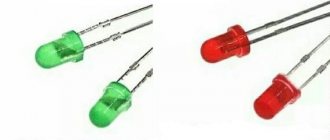
Popular LEDs
As already mentioned, the classification of modern LEDs takes into account their power, color, housing type and a number of other characteristics. The most common are low-power elements in DIP or SMD packages, with a diameter of 3.5-10 mm.
The above parameters may differ depending on the power and purpose of the bulbs. For example, in flashlights, LED strips, and lamps, their power can vary in the range from 0.5 W to 1 W or more.
- The DIP LED is presented in the form of a small light bulb with legs that serve to determine the polarity. Please note that the labeling of some manufacturers may not coincide with the real one.
- The SMD LED has a complicated procedure for determining the anode and cathode. Therefore, quite often craftsmen rely on adequate information from the manufacturer, who marks the cathode with a pictogram or by means of a cut/bevel on the body.
Method for determining the polarity of an SMD LED Source userapi.com
A method for determining the polarity of a small SMD LED Source tempusliberum.ru
A clear example of independent determination of the cathode and anode on an LED of this type is shown in the presented images.
LED polarity: how to determine plus and minus
When using LEDs in creating various circuits, they must be installed correctly. Soldering in most cases does not create problems; determining the polarity is a little more difficult if you do not have experience working with testing equipment.
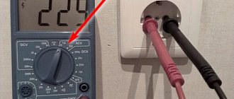
How to determine polarity with a multimeter tester
The easiest way to check the LED is with a multimeter. When connecting the pins in the “dialing” mode to the electrodes, you can get 2 results: the LED lights up and displays a number on the screen depending on the color of the radiation, or shows a very large number. With the first option, we can conclude that the light source is working and connected to the multimeter correctly (plus to plus, minus to minus).
The second method of using a multimeter is to switch to resistance testing. If the red probe touches the plus, the black probe touches the minus, a value in the range of 1600–1800 appears on the screen.
Attention! If the LED is broken (passes voltage in two directions), the number “1” appears on the screen. If there is a break, a very large resistance value appears on the screen, regardless of the location of the probes.
If the multimeter has a PNP compartment, the E (emitter - “+”) and C (collector – “-”) compartments are required to determine the polarity of the LED. The light source glows if the cathode is inserted into “C” and the anode into “E”.
If an NPN multimeter compartment is used, the LED will light if the legs are swapped.
By appearance
In the production of LEDs, different housings are used. DIP elements with a cylindrical body of various diameters are widely used. There are many surface mount SMDs being manufactured. Ultra-bright light sources differ in the size of their housings and crystals. An experienced radio amateur determines the cathode and anode by external signs.
For DIP elements:
- longer anode leg;
- the silhouette in the flask is smaller at the anode, the shape of the cathode resembles a flag;
- a source with a power of more than 1 W has a “+” marking on the anode leg.
Attention! If the DIP LED has already been installed in some device and soldered, the dimensions of the legs may change. Plus and minus are determined by the size of the crystal in the flask or by testing with a multimeter.
For SMD LEDs:
- the cathode is indicated by a cut on the body;
- the heat sink on the back of the case is located closer to the anode;
- The “P” pictogram is facing the anode with the top shelf, the top of the “T” pictogram is facing the cathode.
Methods for determining polarity
There are several ways to find the cathode and anode on a diode. Moreover, each of them differs in the degree of reliability. Among the methods that involve the use of devices, the following are distinguished:
- Measured with a multimeter.
- Supply a limited voltage to the resistor (connecting an independent power source).
- By connecting an oscilloscope.
Such methods have proven themselves well on diodes with low and medium power and a normal glow pattern. Other simple and popular methods include:
- Study the attached technical documents.
- Representation of polarity in a schematic diagram.
Important! We remind you about possible erroneous labeling or inappropriate information in the documentation. This happens quite often.
Links
Wikimedia Foundation. 2010.
Synonyms
See what “Cathode” is in other dictionaries:
- (Greek kathodos descent). The pole of a galvanic pair opposite the anode. Dictionary of foreign words included in the Russian language. Chudinov A.N., 1910. CATHODE in galvanic elements and a volt column, the negative pole, i.e. the end... ... Dictionary of foreign words of the Russian language
cathode
- a, m. cathode f. <English cathode < gr. kathodos way down, descent. An electrode connected to the negative pole of a current source (as opposed to the anode). BAS 1. In the operation of devices such as a galvanic battery, there is no polarity and there will be... ... Historical Dictionary of Gallicisms of the Russian Language
cathode
— cathode A flat piece obtained by electrolysis, intended for remelting. cathode Negative electrode of an x-ray tube [Non-destructive testing system. Types (methods) and technology... ... Technical Translator's Directory
- (from the Greek kathodes, downward movement, return; the term was proposed by the English physicist M. Faraday in 1834), 1) the negative electrode of an electric vacuum or gas discharge device, serving as a source of electrons, which ensure the conductivity of the interelectrode pr... ... Physical encyclopedia
Emitter Dictionary of Russian synonyms. cathode noun, number of synonyms: 4 thermal cathode (1) ... Dictionary of synonyms
CATHODE
— CATHODE, the electrode connected to the negative terminal of the battery. If two metal plates connected to the poles of a battery are immersed in a liquid, the difference between the cathode and the anode will be as follows: if the plates from which the electrodes are made ... Great Medical Encyclopedia
cathode
— electric vacuum device; cathode An electrode, the main purpose of which is usually the emission of electrons during an electrical discharge ... Polytechnic terminological explanatory dictionary
- (from the Greek kathodos move down, return), an electrode of an electronic or electrical device or device (for example, an electrovacuum device, a galvanic cell, an electrolytic bath), characterized by the fact that the movement ... ... Modern encyclopedia
- (from the Greek kathodos, move down, return), in a broad sense, the electrode of various radio and electrical devices or instruments (electron tubes, galvanic cells, electrolytic baths, etc.), characterized by the fact that movement ... ... Big Encyclopedic Dictionary
CATHODE, a negatively charged ELECTRODE in an electrolytic cell or ELECTRONIC TUBE. In the process of ELECTROLYSIS (where electrical energy is used to carry out chemical changes), positively charged ions are attracted to it... ... Scientific and technical encyclopedic dictionary
CATHODE, cathode, man. (Greek kathodos return) (physical). Negative electrode; ant. anode. Ushakov's explanatory dictionary. D.N. Ushakov. 1935 1940 ... Ushakov's Explanatory Dictionary
Books
Methods of experimental physics in selected technologies for the protection of nature and humans: Monograph, Korzhavy Alexey Pavlovich. The book outlines selected methods of experimental physics, created on the basis of vacuum microwave, gas-discharge lasers and sealed-type devices to protect the natural environment and...
Only in one direction. Once upon a time, tube diodes were used. But now semiconductor diodes are mainly used. Unlike lamp ones, they are much smaller in size, do not require filament circuits, and are very easy to connect in different ways.
Symbol of the diode in the diagram
The figure shows the symbol of the diode in the diagram
.
The letters A and K respectively indicate the diode anode
and
diode cathode
.
The anode of a diode is the terminal that is connected to the positive terminal, either directly or through circuit elements. The diode cathode is the terminal from which a positive potential current emerges and then, through circuit elements, enters the negative electrode of the current source. Those. The current through the diode
goes from the anode to the cathode. But in the opposite direction the diode does not pass current. If a diode is connected to one of its terminals, then at its other terminal a constant voltage is obtained with a polarity depending on how the diode is connected. If it is connected by the anode to an alternating voltage, then we will receive a positive voltage from the cathode. If it is connected to the cathode, then a correspondingly negative voltage will be received from the anode.