When hidden wiring is not acceptable
First you need to understand the two main types of hidden electrical wiring. It can be non-replaceable, embedded in the wall or replaceable (in pipes placed in the wall). Serious difficulties arise when installing the system inside a concrete wall. The process is accompanied by gating, but in panel houses there are special restrictions on this. It is much easier to make grooves for wires in a brick wall: it is easy to cut, the cable is conveniently attached inside such grooves.
The permissibility of installing hidden wiring is regulated not only by electrical safety rules, but also by building codes. For example, it is strictly forbidden to groove a single brick of the M-150 brand, since this process will lead to the destruction of the corrugated part of the material. It is also prohibited to place hidden wires inside log houses.
Hidden wiring on combustible bases is prohibited
Tools and attachments used when laying wires in walls
Grooves and holes for socket boxes can be punched with an ordinary hammer and chisel, but in the 21st century, this is done only for small volumes in the absence of power tools or from feeble minds, for sporting interest.
A hammer drill is a universal tool. It can be used as a drill for drilling wood and drywall; in perforation mode, you can drill concrete and brick walls and punch grooves.
Drills with variable speed control are used for drilling only wooden and plasterboard surfaces, as a screwdriver with appropriate attachments. The speed is set depending on the material being processed; more for wood, less for metal.
Attachments for drills and rotary hammers come in a wide variety of designs and purposes:
- Conventional drills for wood, metal, with Pobedit diamond tips for drilling concrete and brick;
- Crowns for drilling wooden and plasterboard sheets;
Drill bit for drilling wood or drywall
- Crowns with tungsten, diamond and pobedit teeth, for drilling brick and concrete walls;
Crown with pobedite teeth for drilling holes for socket boxes in brick and concrete walls
- Titanium tetrahedral bits with tungsten coating for screwing in self-tapping screws.
Tip No. 4 When buying tetrahedral bits, do not save money by buying cheap Chinese metal products, they wear out quickly.
What are the advantages of hidden wiring
To begin with, pay attention to the following: hidden wiring in a frame house or apartment implies destruction of the cladding on the walls and ceiling, the floor surface may be damaged, so you should think about the need for its installation or partial replacement every time a major renovation of the room is carried out. It is much more convenient to carry out the process at new facilities.
The main advantages of organizing hidden cable routing:
- All parts of the system are hidden under a facing layer of plaster or plasterboard sheets, so the appearance of the premises does not deteriorate.
- A high level of fire safety, provided that the walls are made of concrete or other material that does not support combustion. Even if ignited, the fire will not spread, since there will be no oxygen or flammable atmosphere in the walls.
- The cable hidden in this way is well protected from ultraviolet radiation and mechanical shock, which increases the service life of the entire system.
With hidden wiring, the appearance of the walls does not deteriorate.
The disadvantages of this method are primarily related to the complexity of installation, the need to destroy walls and the difficulties that arise when repairing and maintaining the wiring. The cable and other elements are hidden under a layer of plaster, so if necessary you will have to remove it every time. All this cannot be said about electrical systems equipped in an open way.
However, hidden wiring is the most relevant, reliable, safe and correct solution for any permanent housing. In log houses, garages, bathhouses and similar buildings, you can use open electrical wiring.
Exposed retro wiring in a wooden house
Brands of wires laid in walls
The characteristics of wires laid along the walls of various structures depend on many factors:
- Functional purpose of the building;
- Equipment operating conditions;
- On the type of building materials from which the walls are built;
- Requirements of the PUE and other governing documents defining the rules for the design of electrical installations.
Taking these requirements into account, manufacturers make various brands of wires; PPV is considered one of the most popular wires by consumers.
PPV is a wire with a flat configuration, where the cores are placed in one row, and has an insulation layer on each core. The cable is designed to supply power to electrical outlets and lighting networks and can withstand voltages up to 450.
Appearance of PPV with three cores
For laying in walls in residential premises, grades with a cross section of up to 6 mm2 are used. In standard packages, coils are wound in 100; 150; 200m, permissible operating temperature from -50 to +70 ̊С.
VVG - the wire has several models; there is a flat design, similar in appearance to PPV, with double insulation.
Appearance of flat VVG with three wires
There are designs of round, square and triangular shapes.
| VVG brand cables with round cores | ||||
| Number of cores and nominal cross-section (mm²) | External diameter (mm) | Weight of 1 km cable (kg) | ||
| 660V | 1000V | 660V | 1000V | |
| 2:1,5 | 7,5 | 8,1 | 71 | 80 |
| 2:2,5 | 8,2 | 9,6 | 95 | 116 |
| 3:1,5 | 8,1 | 9,4 | 92 | 116 |
| 3:2,5 | 9,3 | 10,2 | 136 | 150 |
| 4:1,5 | 9,2 | 10,1 | 127 | 142 |
| 4:2,5 | 10,1 | 11,0 | 171 | 186 |
| 4:4 | 11,7 | 13,1 | 243 | 273 |
| 4:6 | 13,1 | 14,1 | 325 | 357 |
Table of dimensions of external diameter and weight of VVG wires
Some products contain combustion-preventing additives in the insulation; such wires are marked VVGng.
Cable (NYM) NUM is an analogue of the German wire DIN 57250, flexible, with stranded wires or with a rigid monolithic wire, ideal for hidden wiring in walls in residential premises. This is justified by the composition of non-combustible insulation with reduced emission of toxic gases. The round design has three layers of insulation on each wire, an intermediate layer of chalk-filled rubber and an outer, non-flammable polyvinyl chloride sheath.
Flat installation wire PUNP is the most common and affordable cable in retail chains. Flat-shaped with double PVC insulation, the design can have up to 5 wires.
Tip #1. Experienced electricians do not recommend using PUNP for wiring due to poor quality. Statistics show that 60% of fires due to poor-quality wiring occurred in networks with PUNP wire. 80% of the products on the market are of poor quality, many manufacturers do not comply with technology, the discrepancy is revealed by many parameters:
- Insulation thickness and composition;
- Wire alloy composition;
- Section of veins;
It is safer to buy a more expensive cable and be sure of safety.
Hidden wiring device
Hidden wiring can be done using two methods. The first, classic option is to place cables and network elements inside the grooves or under the casing. The second option, which has been gaining popularity recently, is the use of special pipes and cable ducts. In fact, the wires are hidden from view, but not located inside the wall.
Wiring can definitely be called hidden only in the first case, when the cable is hidden inside building structures. The latter include partitions, various ceilings, floors, walls and ceilings. In most cases, this option involves making special grooves. To make them, use a wall chaser or grinder, but you can get by with a hammer drill or a scarpel with a hammer. The same pipes and channels from the second method should also be present in the first: they are laid in grooves to increase the protection of the wires.
Laying wires in grooves
Attaching cable ducts to the surface of walls and ceilings and then placing wires inside is more of a method of organizing open electrical wiring.
Wall chipping
If the situation is such that it is not possible to lay a cable on bare rough walls or the layer of plaster is too thin, then the walls will have to be tapped. A groove or rectangular recess in the wall for cables is called a groove. It is simple to do, but often very labor-intensive.
You should start with markings. After this, a tool for this job is selected: an angle grinder, a hammer drill or a wall chaser. Due to its high cost, not everyone uses an electric wall chaser, although it is very convenient. Much more often a grinder or a hammer drill is used. Wear safety glasses and clothing when working with these tools. The dust raised may be so thick that you cannot see anything at arm's length. If you don’t have a power tool, you will have to chisel and hammer. This is very labor-intensive, and besides, the excavation will be uneven, and there is a danger that part of the plaster will fall off.
Groove in a concrete wall
The depth of the groove must be sufficient for the cable to be hidden in it with a reserve. Please note that in this case the socket box is usually installed in the wall. It is more careful and easier to work with an angle grinder, especially if there are several wires in the groove. For cutting plaster or brick, replaceable stone discs are used; for hard reinforced concrete, diamond bits are used. Along the entire length of the cable, 2 parallel lines are cut to a sufficient depth to hide the wire, and another couple of millimeters are taken in reserve (you still need to hide the fasteners).
After the cable is fixed in the groove, it is covered with plaster - cement or gypsum
The width of the groove depends on the number of wires. It must be remembered that they should be located at a distance of 3–5 mm from each other. Having cut through these 2 lines, using a regular chisel or hammer drill, knock down the jumper between them - and the groove is ready. Now you can install the cable into it. The wire is secured with the same hooks. Now the groove can be covered with plaster. Before doing this, you need to check again that everything is in place and that the ends of the wires are extended to a sufficient length.
After the wiring is laid in the groove and plastered, you can proceed to other types of finishing
Before plastering, you need to clean the dust from the grooves with a brush and cover the recess with a primer. After this, dilute the required amount of plaster mixture and apply it with a spatula, pressing the grooves inside. Then, use a wide spatula to remove excess plaster and leave the mixture to dry for about a day. In the places where the junction boxes will be located, the wires remain hanging in bundles.
The ends of the wires are twisted together and insulated
The boxes are installed after the grooves are sealed, since it is not always clear at what depth to install them.
Requirements for hidden wiring in the house
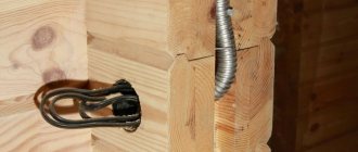
The main requirement when installing hidden wiring in a residential building is an increased level of fire safety. Therefore, if work is carried out in a wooden house, it is important to use special steel or polyvinyl chloride pipes to place the wires. In a brick or concrete building, the cable can be hidden in ordinary grooves or a corrugated pipe located behind cladding made of plasterboard and other materials.
The second important requirement is the accessibility of electrical wiring and the ability to quickly replace it. It is necessary to create a system that will make it possible to easily replace or modify the line without removing wall cladding or other damage.
However, there are often situations when, due to some unplanned circumstances, this requirement is not complied with. It is difficult to imagine a situation in which it becomes possible to punch a groove in the wall, the dimensions of which are suitable for placing a pipe. Therefore, to ensure replacement, it remains to use corrugated pipes hidden under the sheathing (and not plaster) or under the floor.
The use of corrugated pipes allows you to quickly replace wiring
The most specific requirement for the installation of hidden wiring is related to the route of the cable line. Chaotic laying of the cable in the wall is unacceptable: avoid situations where in one place the route moves parallel to the wall, and in another it unexpectedly turns diagonally.
On the one hand, this way you will save materials and time, on the other hand, you will ignore an important rule, which will complicate the task of finding wiring in the future. The cable line must be located strictly vertically or horizontally under the ceiling or at a height of 2.5 m. The wires under the floor must run parallel to a pair of walls. In the future, you may have to drill into the walls to hang a picture or shelf. If the cable is positioned as you please, the risk of an error associated with the drill hitting the wire increases. The electric drill will break, the functionality of the wiring itself will be impaired, and in rare cases you can get a serious electric shock.
When organizing hidden or open electrical wiring, you need to think about electrical safety. When arranging systems like TN-S or TN-CS, it is important to have a third conductor (PE). In situations where its switching is impossible due to the lack of a corresponding cable in the distribution panel of the entrance, it is still recommended to lay a cable line of three wires. The yellow-green conductor used for grounding will come in handy later when the wiring in the house is finally grounded. In rooms with increased danger (bathroom or kitchen), it is recommended to install residual current devices or differential circuit breakers.
Organization of wiring in a private house according to the TN-CS scheme
Hidden wiring diagram
The first stage is preparation for installation of hidden wiring. You need to decide on the type of branching of the electrical network, which can be boxed or daisy chained. In the first case, one cable is allocated per apartment area. Then branches are made from it to separate rooms, and special junction boxes are installed.
The loop branching is organized according to European standards. This option involves laying two cables. One of them is used for switching sockets, the other for lighting fixtures. The wires are connected from the distribution panel and laid to each room where there is a switch.
Electrical wiring diagram in the cottage
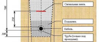
The second stage is drawing up a diagram of the location of lighting fixtures and branch boxes for switches. It is necessary to draw a schematic representation of the cable line along which the wires will be laid. They are installed at a height of at least 150 mm from the floor and with a distance from the ceiling of 100 mm or more. A similar distance should be to windows and doors. The rise of the route to the locations of sockets and switches is carried out strictly vertically, perpendicular to the floor.
Other recommendations:
- make sure that the wires do not cross in any places;
- Load-bearing walls cannot be tapped, so hide the wires under a thick layer of plaster;
- first draw up a diagram on paper, then transfer it to the surface of the floor, walls and ceiling.
Marking the electrical wiring route on the walls
How to properly lay cables in the floor
You should remember the basic rule: when installing a cable in a concrete floor, ordinary corrugation is used, and when installing in a wooden floor, metal is used. Laying wiring without any protection is prohibited by all regulatory documents.
What you should know when starting to install electrical wiring on the floor:
- All connections must be made only in junction boxes. The presence of twists in the floor, without additional protection, is unacceptable. Also, other types of connections cannot be left open: using sleeves or terminal blocks, bolted connections, etc.
- It is very convenient to place the junction box on the floor surface. This allows you to quickly identify and eliminate the problem without compromising the integrity of the floor covering.
- The corrugation should not be filled more than half with cable. This should be taken into account and a corrugation of the appropriate diameter should be selected. Only then, to replace the wire, can it be completely removed from the floor.
- You should not install too long lines - 20 m is enough. If the use of longer conductors is required, then special transit boxes must be used.
- There should not be more than two bends on one cable, the angles of which are 90 degrees or higher. This will have a detrimental effect on the further operation of the electrical network and, if necessary, the conductor will be impossible to get.
- When laying a cable in a wooden floor, you should not attach it to the joists; in this case, special holes are made in them, through which the corrugation is then passed. The presence of such holes will not affect the stability of the floor covering in any way. For additional safety, all wooden floor elements must be treated with a special composition that prevents combustion.
- When starting to pour a concrete floor, you must remember that the thickness of the cement screed above the wiring should be approximately 30 cm. For better stability (but not for electrical safety purposes), reinforced mesh is also placed in the screed.
- The corrugation with conductors should not intersect; all cables should run parallel to each other. When crossing them, it will be necessary to raise the floor level, which implies additional consumption of building material.
Materials and equipment for hidden electrical wiring
You don’t need to think long about choosing a cable: a regular one, brand VVGng, will do. If budget allows, NYM wire can be used instead. Both of them are characterized by a long service life and have high strength, due to which they can withstand wet sealing in grooves.
The cable cross-section must comply with the standard:
- lines for lighting devices - 1.5 sq. mm;
- connection of sockets - 2.5 sq. mm;
- electric stove - 4 sq. mm.
Selecting the cable cross-section for open and hidden wiring
You can take any distribution boards. Even products that are formally used in arranging open wiring are suitable. The situation is similar with switches and sockets. However, special devices for hidden installation take up much less space, look miniature and do not violate the integrity of the interior. However, in this case you will have to install socket boxes and junction boxes. There are components for solid and cavity walls.
Laying wires on brick and concrete walls without gating
In these cases, it is very convenient to use flat-shaped wires. Along pre-marked routes, the wire is attached to the walls with plastic staples with high-strength nails or plastic dowels with clamps. Previously, fastening was carried out with tin plates, which were screwed to the wall with self-tapping screws onto a plastic dowel or simply aimed at the wall with a construction gun.
For socket boxes and distribution boxes, holes are drilled using a hammer drill with special concrete bits. The body of the socket box is inserted into the hole and attached to the gypsum mortar; before this, wires are inserted into the side technological holes.
Tip No. 3 It is recommended to drill holes for socket boxes after the surface of the wall with the wiring lines is plastered. This technique will ensure that the top edge of the socket cup is installed at the same level with the wall surface.
If you install the socket box earlier, it will be difficult to achieve a clear match of the levels, and differences lead to problems when installing sockets. If the socket box is deeply recessed, the bolts securing the front panel of the socket may not reach the threads on the body. If the socket box protrudes, there will be a gap between the wall and the front panel.
Distribution boxes and socket boxes are manufactured according to certain standards. The diameter and depth are selected depending on the size of switches and sockets; for distribution boxes, the number of wires that are inserted into it is taken into account. If there are a large number of wires with a large cross-section and the outer diameter of the cable of a round structure, it is recommended to make grooves in the walls.
Hidden electrical wiring installation technology
After drawing up the diagram, it needs to be transferred to the surface of the walls. This applies to cable locations, sockets, switches, boxes and lighting fixtures. Be sure to mark the area where the electric stove will be placed, if one will be used. When measuring the height from the floor, take into account future work on laying tiles, laminate or other materials.
The third stage is to use a tool to make grooves for the cable and recesses for the socket boxes. Immediately after this, you can proceed to laying and fastening the wires. The latter can be easily done using dowel clamps (UW), also called “lashes”. The dimensions of the fastening element directly depend on the thickness of the insulation of the mounted conductor.
Fastening the cable using dowel clamps
They are easy to use: at the attachment point you need to drill a hole of a certain depth and appropriate diameter. Then you should wrap the cable with a dowel clamp, after which its antennae should be placed in the hole. Those who want to save money can use a simpler method: after laying the wire in the grooves at a certain distance, it is smeared with alabaster.
Before attaching the wire, it should be straightened to avoid bending or twisting. Where the line turns, the wire should bend smoothly. At the points where the boxes are located, you need to leave a cable reserve of 15–20 cm.
The fourth stage is the installation of distribution boxes and socket boxes. But first, be sure to make sure they are working. Also check that the box fits freely into the recess. It must be completely hidden. Moisten the installation site with water and spread a layer of alabaster. On the side of the box where the wire will be, remove the partition, thread the cable and insert the product into the niche.
The box should be flush with the wall. Otherwise, the switch or socket will stick out from the wall surface, which will compromise aesthetics and safety. At the end, finishing work is performed, wires are connected and power is connected.
Wall chipping
A groove is a special groove or rectangular hole in the wall in which the cable is placed. The gating process takes a lot of time and effort. For increased safety, wear goggles and a respirator mask to protect your vision and breathing, respectively.
The ideal solution to the problem would be to use a wall chaser. The tool is not cheap, so not everyone will want to buy it for repairs in one apartment. You can replace it with an electric grinder, equipping the device with diamond wheels or discs for concrete.
Chasing walls for electrical wiring
Cut two strips parallel to each other, then use a chisel and hammer to knock out the rest of the wall between the slots. The width and depth of the groove depend on the number of cables being installed. In this case, there should be a margin of about 10 mm in each direction.
When operating a hammer drill, you need to drill several holes of a suitable diameter at a distance of 5–10 mm. Then the partitions between them are removed with a hammer and chisel. For recesses under boxes and socket boxes, you need to use a hammer drill equipped with crowns with a drill in the center. If there is no crown, then use a regular drill to make several holes in a circle, and then remove the partitions.
Laying grooves using a hammer drill
Laying electrical wiring in pipes
To increase the safety of future electrical wiring, you can use special tubes. This installation method is usually used for rooms with high levels of humidity or rooms with significant temperature changes: baths, basements, bathrooms.
In addition to the high level of security, this method is also good because it provides the ability to replace the cable. The installation process is practically no different from the usual method. The only exception is the need to create wider and deeper grooves. The pipes are fastened inside them using “welds”, alabaster or staples.
Plastic pipes for cable laying
Cable laying in partitions, floors and ceilings
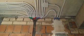
A suspended ceiling made of plasterboard mounted on metal structures can greatly simplify the task. In this situation, there is no need to groove the walls horizontally, and the wiring will be hidden under the finishing sheets, from where it is brought to the walls and lowered vertically to the connection points for sockets and switches.
Junction boxes can be installed in the same place, which will avoid drilling holes for them. However, this option involves installing plastic hatches with a pointer directly in the drywall, through which you can get to the boxes. The wires are attached to the ceiling using “hooks” or ordinary clamps.
Installation of wires along the ceiling in corrugated wires
The wiring can be placed in plastic pipes, which are attached to the ceiling using clips. This method increases the level of fire safety. An alternative solution is to lay the cable in the floor if it is lined with wood or gypsum fiber boards. For the first option, you can drill or cut holes directly in the joists, then insert plastic pipes with cables through them; for the second, lay the wires on the floor, secure them with brackets and cover them with expanded clay or other filler. The flooring is laid on top.
Electrical wiring can be hidden in pipes and then covered with cement screed. If the solution layer is too thin, then this option is undesirable.
Note. It is forbidden to connect wires behind cladding, partitions or in the floor. When using one of the listed methods, switching is possible strictly in junction boxes.
Installation of the junction box
When installing distribution boxes in concrete walls, making a hole with a hammer drill, use a diamond-coated drill bit. Conventional components with a pobedit drill wear out too quickly, and you will be forced to buy new ones. On the other hand, it is not possible to use diamond drill bits for finblocks.
Before you start milling, make a hole in the center of the mounting location, the diameter of which corresponds to the drill. The diameter of the installed boxes should be about 60–70 mm, which is enough for six conductors.
Distribution box for hidden electrical wiring
Installation of socket boxes
Having created the holes, install socket boxes and switch boxes. For reliable fixation, use alabaster, which ensures good fastening of the plastic to the concrete. The edges should be mounted flush to avoid difficulties in the process of decorative wall treatment.
Mounting strip for socket boxes
Finally, we emphasize that hidden wiring is done for several decades in advance, so saving on the quality of the materials used is highly not recommended. After purchase, perform a preliminary inspection to ensure there is no damage and that there are no insulation problems. Play it safe once again, since getting to the wiring in the future will be problematic. Wall, floor or ceiling cladding should be installed only after checking the functionality of the electrical network. Don't forget about safety precautions.
Features of electrical wiring in the floor
Preferred areas of use.
Laying cables in the floor is most appropriate for new construction when the room is in “bare walls” condition, i.e. in fact, in new buildings (as shown in Figure 1). This allows you to minimize the time and effort required to carry out electrical wiring due to the large free space and the ability to eliminate the need for wall chiselling.
Figure 2 shows that this provides the greatest benefit in the area near the central distribution panel.
Rice. 1. Formation of a system of underground channels at the rough finishing stage
Rice. 2. Inserting corrugated tubes into the central electrical panel
For wooden houses in which the floorboards are laid on massive joists, there is enough free space for the channels of the type in question along with the distribution boxes. This allows this type of wiring to be used also during major repairs.
Rules for forming channels and pulling cables.
When forming channels, it is advisable to minimize the number of turns. Although current regulations allow two or even three turns, it is advisable to perform no more than one.
The maximum length of a straight section should not exceed 15 m.
When laying several channels, they should be placed in parallel; when turning, intersections are not allowed (this rule is shown in Figure 2).
Rice. 3. Rules for parallel laying of several channels
An example of improper planning of a canal system with a large number of intersections is shown in Figure 4.
Rice. 4. Incorrectly planned canal system with a large number of intersections
It is advisable to leave a long cord made of wire, cable or plastic rod in the laid channel, which is used to tighten the cables.
To facilitate pulling and replacing wires, they should not fill more than 50% of the channel cross-section “in the clear” (0.6 of the pipe diameter).
To minimize the forces applied to the cable when laying in a non-linear channel, its direction should be chosen so that the turn is closer to the beginning of the channel, and not to its end. This situation is shown in schematic form in sketch Figure 5.
Rice. 5. Rules for choosing the direction of pulling cables in pipes with turns