The electromagnet was invented 200 years ago and since then little has changed in its design. But now there is more knowledge and technological capabilities to make miniature electromagnets with low power consumption, with the ability to supply DC or AC power and other features. Electromagnetic relays (or simply relays) are components that are most often enclosed in a rectangular housing with leads for soldering or mounting into a socket. Inside there is an electromagnet, a metal armature that moves the contacts.
Application
Solid state relays are used to control electronic devices, equipment and automatic systems connected to an electrical network with a power of 20 to 480 watts.
Used in various fields:
- automation of industrial processes;
- various household installations;
- heat regulation systems in heating elements;
- in lighting control systems and motion sensors;
- car electronics.
The relay is found in refrigerators, kettles, washing machines, heating elements, and uninterruptible power supplies.
The areas of use of solid-state devices depend on their design, connection diagrams and other operating conditions.
TSRs do not require constant maintenance and can be installed in any hard-to-reach places.
The popularity of solid-state devices is increasing every day, thanks to widespread automation.
Types and classification
By installation method
Various models of SSRs are available with mounting on supporting surfaces, printed circuit boards or DIN rails.
Figure 3. Device for installation on a printed circuit board.
To cool the relay, special radiators are used, installed between the support and the block.
For additional protection against overheating, thermal paste is applied to the surface of the device to increase heat transfer by increasing the contact area.
There are models designed to be attached directly to the wall with screws.
For installation in an electrical panel, TTRs with DIN rail mounts are available.
Rail mounting.
To remove excess heat, the relay is attached to the rail through brackets.
By type of switching network switching
The devices differ:
- With a “through zero” regulator. Triggered at zero voltage. Designed for devices with weak inductive, resistive or capacitive loads.
- Instant. Used when sudden operation is required.
- Phase. In such devices, when the resistance value changes, the power at the load changes. It is used to adjust the lighting level in incandescent lamps, or the temperature in heating elements.
By type of operating current
Solid state relays can be controlled by electrical circuits with two types of current:
- permanent;
- variables.
DC switching is used at constant voltages up to 32 volts.
Most operate on alternating currents. Such devices are characterized by instantaneous operation, efficiency and low degree of electromagnetic interference. Operating voltages are 90-250 volts.
By number of connected phases
There are:
- Single-phase, operating in the range of 10-100 and 100-500A, are installed in household appliances.
- Three-phase, 10-120 A, switching voltage on three phases at once.
Single-phase devices are controlled using an analog signal and a variable resistor.
The design of three-phase relays involves reversible operation, providing regulation of several electrical circuits simultaneously.
Three phase relay
To make the correct connection when installing equipment, wires of different colors are connected to the three-phase relay.
Types of solid state relays
SSRs are conventionally divided according to two criteria - the principle of operation and design features. To simplify the classification, we highlight the following options:
- By type of control signal - variable or constant I.
- According to the type of main (switched) voltage - constant or alternating.
- According to the number of phases (for alternating voltage) - one, three.
- According to the presence of reverse - provided, not provided.
- According to the subtleties of the design - on a DIN rail or on a surface.
Design
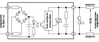
The main element of solid-state relays is an electronic board consisting of three main elements:
- A control unit that provides stable voltage levels, which at the input ranges from 70 to 220 Volts.
- Interchange unit , consisting of elements that send and receive a light signal. A transparent dielectric is located between the transmitting and receiving elements.
- Power keys:
- for direct current - based on transistors.
- for variable - on base
triacs or thyristors.
Relay internals.
The device must be mounted after the load, followed by grounding, to prevent short circuits.
Connection diagrams
Electrical circuits are constructed depending on the characteristics of the load connection.
The most common schemes include:
- Open or open . When a control signal is present, the relay is energized. When the inputs are de-energized, the devices are in a switched off state.
- Closed. In the absence of a control signal, the relay load is energized. When the inputs are de-energized, the connected devices are in working order.
- Three-phase - contacts are connected according to the “Star”, “Star-neutral” or “Triangle” circuit.
- Reversible - include two levels of control. Manufactured in a three-phase version.
Electrical circuits with solid-state relays are assembled exactly according to the diagram, observing polarity.
Incorrect connection of devices can lead to electric shock or failure due to short circuit.
yourmicrowell.com
The device that will be discussed in this article can be called differently: starting relay, unloading relay, delay relay, and each of these names, in my opinion, will be correct. Why? We will find out this later, but for now we will focus on one of the names - starting relay, and figure out what it is for and how it works.
From the contents of the previous article, it is known that the timer-controller contains two groups of contacts connected to each other in series: timer contacts - K-time and power regulator contacts - K-power. During operation of the microwave oven, these groups have to switch fairly high power currents - at least 700W. This is a current of approximately 3 amperes at 220 volts. And, in ovens with a grill function, this figure will be almost twice as much. Switching such a high power inevitably causes sparking between the contacts at the moment of their operation, which leads to burnout of the working surface of the contact group and, as a result, negatively affects the operation of the furnace. Despite the statement of the manufacturers of mechanical regulators that its contacts are designed for a fairly high current, 10 - 15A. at a voltage of 250V. (these parameters are usually indicated on the regulator body) in practice, in furnaces that do not have a start relay, failure of the timer-regulator contacts occurs much more often than in furnaces equipped with this device. Service centers rarely bother to repair individual components and parts of a microwave oven. Therefore, if the contacts of the timer-regulator in your microwave burn out, the service will most likely offer you to change it entirely, which will negatively affect the contents of your wallet. To ensure that such situations arise as rarely as possible, manufacturing plants try to relieve the load and secure the contacts of the mechanical regulator by equipping furnaces with devices such as a starting relay.
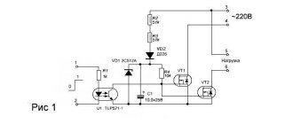
Picture 1
Figure 1 shows a diagram of a microwave oven with a mechanical control panel. The section of the circuit outlined with a red dotted line is the starting relay. The main element of the device is, in fact, the “P” relay with “KR” contacts. This relay is most often designed for an operating voltage of 24 volts DC. The remaining elements of the circuit form a half-wave, transformerless power source that ensures the operation of the relay. In the diagram, the position of the contact groups of the locking keys: K1, K2 and K3 correspond to the state of the open door. Let's mentally close the door, that is, let's move the position of all the keys to the opposite state - closed. Let's turn the time regulator knob clockwise, thus closing the contact groups of the timer - regulator, K-time and K-power, in a word, mentally turn on the oven - apply supply voltage to the load. After K-time and K-power are triggered, current will flow through them to the load - the primary winding of the high-voltage transformer. But, since the “KR” contacts of the “P” relay are currently still open, the current will flow through the quenching resistor R2. Due to its rating, R2 will absorb a significant part of the current and voltage. The part of the power that it will transmit will not be enough to generate the voltages necessary for the operation of the magnetron on the secondary windings of the high-voltage transformer. In other words, at this moment, our oven is not working. On the other hand, such a limitation of the current power flowing through the K-time and K-power contact groups significantly reduces the likelihood of sparking between their contacts at the moment of operation. That is, by switching not the full power, but the power limited by R2, the contact groups of the regulator are, as it were, unloaded - they operate in a gentle mode. At the same time, a supply voltage of 220 volts, through limiting resistor R3, is supplied to the rectifying diode VD1. VD1 will only allow positive half-cycles of alternating voltage to pass through, which will go to the upper - positive plate of capacitor C4. After applying constant voltage to capacitor C4, it will begin to charge. The tension on its plates will increase. When the voltage level on C4 is equal to the relay operating voltage, relay “P” will operate, contacts “KR” will close and will bypass resistor R2. As a result, full power will begin to flow into the primary winding of the high-voltage transformer. The voltages necessary for the operation of the magnetron will appear on the secondary windings of the transformer, and the furnace will start. Zener diode VD2, in this circuit, performs a dual function. As the voltage on capacitor C4 increases, the zener diode limits its level to the required level (24V), and when the relay is de-energized, it extinguishes the reverse currents that arise at that moment in the relay coil due to the phenomenon of self-induction. When K-power or K-time is opened, voltage stops flowing to the starter circuit, capacitor C4 is discharged through the relay winding, relay “P” opens the contacts “KR” and thereby de-energizes the load. The oven turns off. Thus, the charging time of capacitor C4 creates a certain pause, during which the contact groups of the regulator do not switch the full voltage, but limited by resistor R2, which reduces or completely eliminates sparking between the contacts, and thereby significantly extends their service life.
Figure 2
Structurally, the starting relay is most often carried out using the printed circuit mounting method on one board together with a power filter. Inside the oven, this unit is usually mounted on top of the fan housing located at the back wall of the microwave. But other location options are also possible, for example, above or next to a high-voltage transformer. Figure 2 shows one example of a starting relay and mains filter unit. This board can be easily distinguished from other electronic units of the furnace by the presence of high-power resistors in ceramic cases. On the example board, resistor R2 has a value of 30 ohms, and R3 has a value of 5.4 ohms. Both resistors are rated at 10W. dissipated power. The use of such powerful resistors is due to the fact that the mains voltage is converted to 220V. To obtain a voltage suitable for powering the relay, a significant portion of the voltage and current must be extinguished. In this case, the extinguished power is released by resistors in the form of heat. To increase the reliability of this device, manufacturers can use composite resistors. That is, in place of one 5.4 kΩ resistor with a power of 10 W, two 2.7 kΩ resistors with a power of 5 W each connected in series can be installed. So, don’t be surprised if, if you need to repair this unit, you find not two resistors on the board, but more.
Operating principle
To understand the operating principle of solid-state relays, you need to know their design features.
The interaction of the controlled and control signal is ensured by galvanic or optical isolation.
One of the main elements of the SSR is an opto-isolator, or optocoupler in the form of an LED and a photosensitive device that isolates the input from the output.
When electricity passes through the LED connected to the input section of the solid state relay, it lights up. Focusing through the gap, the light is transmitted to a photosensitive transistor or semistor.
The principle of operation of the device is to close and open contacts that transmit voltage.
The circuitry of all solid-state devices is approximately the same. Minor differences between different models do not affect its functionality at all.
The mechanism works by closing and opening the contact terminals that transmit voltage.
Specifications
When choosing a TSR, one is guided by the following characteristics:
- dimensions;
- voltage value at the input and output;
- overload capacity;
- power consumption;
- material of manufacture;
- type of installation;
- insulation strength, etc.
The characteristics of solid-state relays may vary depending on the type of device.
Table 1. Average characteristics of TSR.
| Name | Index |
| Operating currents | no more than 7.5 mA |
| Insulation resistance | >50 MOhm/500V DC |
| Relay control method for DC current | instantly via optocoupler |
| Switching method in relays for alternating current | when crossing zero |
| Overload capacity | up to 10 rated currents for 10 ms |
| Built-in protection | replaceable fuses |
| Insulation strength | 2.5 kV AC for 1 minute |
Microelectronic relays from OMRON Corporation
March 3, 2008
The main advantages of microelectronic relays, compared to electromechanical ones, are:
- durability;
- high reliability;
- small sizes;
- silent, non-contact operation;
- no need for maintenance.
OMRON Corporation produces two types of microelectronic relays - solid-state relays and MOSFET relays.
Solid State Relays
Relays of this type are capable of switching alternating current in the optosimistor version or direct current in the optothyristor version. Optionally, optosimistors can have the function of turning on the output signal when crossing zero, as well as built-in varistors to suppress switching noise.
Table 1 shows the main parameters of some families of solid-state relays with different output elements.
Table 1. Basic parameters of some families of solid-state relays with different output elements
| Parameter | G3DZ | G3M | G3MB | G3MC | G3R/RD | G3S/SD |
| Output element | Photodiode assembly | Phototriac | Phototriac/Photocoupler | |||
| Load voltage, V (AC) | 3…264 | 75…132 | 75…132 | 75…132 | 75…264 | 75…264 |
| 3…125 | 75…264 | 75…264 | 75…264 | |||
| Load voltage, V (DC) | 3…125 | 3…26 | ||||
| 3…52,8 | ||||||
| Load current, A | 0,6 | 2; 3; 5 | 2 | 1; 2 | 1,5; 2 | 1; 1,1; 1,2 |
| Input voltage, V (DC) | 5, 12, 24 | |||||
| Insulation voltage, V (AC) | 2500 | |||||
| Temperature range, °C | — 30…80 | |||||
| Replacing an electromechanical relay | G6D | G6B | ||||
One of the important features of such relays is the ability to replace some types of electromechanical relays manufactured by OMRON with solid-state ones without reworking the printed circuit board, that is, they are pin-to-pin compatible.
For reference: www.omroncomponents.com/home/products/Relays/SolidStateRelays.
MOSFET relay
OMRON MOSFET relays are manufactured taking into account the latest advances in microelectronics and embody many modern technologies in the field of LED and photodiode technology, as well as field-effect transistors. As a result, this made it possible to achieve minimal chip sizes and their power consumption. All relay models contain a dual MOSFET load circuit, providing complete versatility in their use, since these devices do not matter whether the load is connected to AC or DC, and in which direction. Examples of switching relay outputs for different types of voltages are shown in Figure 1.
Rice. 1. Options for switching relay outputs for different types of voltages
The built-in current limiting function is widely used in telecommunications equipment to limit excessive current during fault conditions, as well as to counter current build-up during transient conditions. These relays are ideal for use in mini-automatic telephone exchanges for solving problems of seizing and switching a line, for organizing data access, for controlling linear transformers, etc.
Relays, depending on the possible application, are divided into the following groups:
- General purpose;
- Special purpose, usually low voltage;
- Designed for use in telecommunications equipment with increased dielectric strength or built-in current limiting function;
- High quality with reduced channel open resistance.
In addition, each type of relay has options, both with normally open contacts and with normally closed contacts.
The MOSFET relay markings are shown in Table 2.
Table 2. MOSFET relay markings
| G3VM - xxxx | Load voltage, V | Type of contacts | Type of shell | Additional functions |
| 2…20 4…40 6…60 8…80 10…100 20…200 25…250 35…350 40…400 60…600 | 1 - SPST-NO 2 - DPST-NO 3 - SPST-NC 4 - DPST-NC 5 - SPST-NO + SPST-NC | A - DIP 4 B - DIP 6 C - DIP 8 D - SMD 4 E - SMD 6 F - SMD 8 G - SOP 4 H - SOP 6 J - SOP 8 L - SSOP 4 | L - with current limiting function R - with low channel resistance Y - with increased dielectric strength > 2.5 kV |
In general, the designation system is quite transparent, and any developer can choose the necessary relay based on the required parameters.
Table 3 below shows the parameters of some types of the most popular MOSFET relays with field-effect transistor output.
Table 3. Parameters of some types of MOSFET relays
| Parameter | G3VM-351A | G3VM-353A | G3VM-61G1 | G3VM-62C1 | G3VM-354C | G3VM-355CR | G3VM-355JR |
| Contact type | NZ* | HP** | NZ | Two groups of NC | Two HP groups | One NC, one NO | One NC, one NO |
| Output voltage, V (AC) | 350 | 350 | 60 | 60 | 350 | 350 | 350 |
| Load current, mA | 120 | 150 | 400 | 500 | 150 | 120 | 90 |
| LED input voltage, V (DC) | 5 | ||||||
| Insulation voltage, V (AC) | 2500 | 1500 | 2500 | 1500 | |||
| Temperature range, °C | -40…85 | ||||||
| Maximum LED operating current, mA | 3 | ||||||
| Maximum on/off time, ms | 1/1 | 1/3 | 2/0,5 | 2/0,5 | 1/3 | 1/1 | 1/3 |
* NC - normally closed contact ** NR - normally open contact
To provide electronic equipment developers with detailed information, OMRON produces a complete product catalog with data sheets, CD-ROMs with similar information and visual brochures with the main relay parameters. In addition, help information can be obtained by emailing https://www.omroncomponents.com/home/products/Relays/MOSFETRelays/ or visiting the company website https://www.omroncomponents.com/ .
Responsible for the direction at COMPEL - Alexander Raikhman
Obtaining technical information, ordering samples, delivery - e-mail
Additional features of the B6TS touch sensor
OMRON engineers have developed a 16-channel version of touch sensors for the existing B6TS series. The new B6TS-16LF is capable of controlling 16 different buttons using one chip, while having higher sensitivity and programmability.
The B6TS sensor responds to most non-conductive materials: rubber, wood, glass, various plastics and even marble, which makes it possible to use these materials as a decorative coating for control elements. Devices where B6TS is applicable (vending machines, elevators, various access systems) are subject to increased requirements for appearance and design. Omron engineers have given designers greater design freedom with the ability to build their own electrical circuits and independent electrode configurations.
•••
Our information channels
The difference between solid state relays and electromagnetic ones
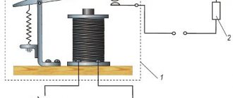
Electromagnetic models have a control coil and a movable contact group.
The coil is supplied with voltage from a push-button station or control system.
Electricity flowing through the coil creates an electromagnetic field that attracts the armature with the contact group. The contacts are closed.
The main difference between solid-state relays is the absence of a control coil and a movable power contact group.
Depending on the scope of application, the functions of power contacts are performed by transistors, thyristors, triacs and other semiconductor switches.
Due to the absence of moving parts, solid-state relays are not subject to mechanical wear.
Figure 7. Disassembled device.
Connecting a solid state relay
The connection principle is simple. The device has control inputs (voltage is supplied to them with strict polarity) and an output for connecting a load. An important point is the quality of the connection. The screw method is used here (soldering is excluded).
To avoid damage to the SSR, it is important to prevent dust and foreign mechanical elements from coming into contact with the contacts. It is worth taking measures to prevent negative impacts on the device casing (on or off).
After switching on, do not touch the housing, which may be hot. Please note that the TSR is not located near flammable materials. In addition, during the connection process, make sure that the connections are completed without errors.
If, after switching on, the product reaches a temperature above 60 degrees Celsius, install a radiator on it for cooling (the reasons and features of this protective measure are discussed above).
If nothing is done, the device will stop working when it reaches 80 degrees Celsius. Control is carried out using a chain with various design options.
Advantages and disadvantages
The advantages of solid-state models include:
- absence of noise and vibration;
- compact dimensions;
- wide scope of application;
- instantaneous switching speed (thousandths of milliseconds);
- no electromagnetic interference when turned on;
- long service life due to the absence of moving parts;
- constant output resistance throughout the entire service life;
- minimal electrical energy consumption;
- possibility of load regulation;
- low sensitivity to vibrations, high humidity, dust, and magnetic fields.
The switching life of solid-state relays is a thousand or more times higher than that of electromagnetic analogues.
When operating such devices, the possibility of sparks occurring during switching is eliminated, which allows the devices to be used in explosion- and fire-hazardous facilities.
The main disadvantages of solid-state relays:
- heating of the device due to high resistance in the pn junction circuit;
- frequent false alarms during power surges;
- the possibility of failure of the power switch due to overloads and short circuits;
- high price.
The SSR has a leakage current, due to which the phase wire may be energized even when the relay is turned off.
Devices designed to operate in direct current conditions require strict adherence to polarity when connecting output circuits.
Solid state relays are periodically checked for package integrity and insulation.
Design and operating principle of solid state relay
Based on the technology used to create solid-state relays, they can be classified as hybrid devices. The function of the contact group in solid-state relays is taken over by an electronic power switch. This avoids arcing during the switching process. This quality is indispensable when operating the unit in areas of heavy chemical contamination.
Other advantages of the element include:
- ultra-fast response to an incoming signal (thousandths of milliseconds);
- no hysteresis;
- large operating temperature range;
- silent change of circuit parameters.
Solid-state relays perform their main function using semiconductor elements. The operation process is similar to a classic relay, which, as we know, includes control coils and special contacts. When voltage is applied, the contacts close or open. An alternative to these contacts are semiconductor devices.
Most often, solid-state relays include triacs, thyristors and transistors. Devices produced in mass production contain elements that make it possible to regulate current up to 100+ A.
Selecting a Solid State Relay
The overload properties of SSRs that switch alternating current are significantly higher than those of devices that switch direct current.
Table 2. Relay overload capacity.
| Current type | Permissible maximum overload (Ampere) during 10 ms. | ||
| Constant | 90 | 250 | 380 |
| Variable | 120 | 300 | 410 |
When choosing, you need to consider the following aspects:
Switching methods
The most popular devices are those in which control is performed when passing through “0”.
This type of switching is suitable for resistive type loads. The method allows you to eliminate interference created when turned on.
Phase control
The phase method is used in resistive lighting control circuits, transformers, and infrared emitters.
The regulation process in phase control is smooth and seamless. The disadvantage of this method is the appearance of interference during switching.
Phase controlled relay.
A relay with a phase regulator can be recognized by its symbol on the body, in the area where the input terminals are located.
Parameters and types of loads
Load current is one of the most important parameters when choosing a relay.
For reliable operation, choose a relay with a reserve:
- 30-40% - with active load (heaters);
- 6-10% - for asynchronous electric motors;
- 8-12% - for incandescent lamps;
- 4-10% - for electromagnetic relay coils.
Particular attention is paid to the following parameters:
| 1. Load current limit | ranging from 10 to 500 amperes |
| 2. Switchable voltage level |
|
| 3. Control signal |
|
To connect an inductive load (for example, an electric motor), it is necessary to take into account the starting current, which exceeds the rated current by 600-100%
Availability of cooling
The reliability of solid-state relays depends on its operating temperature.
The temperature should not be allowed to exceed 60°C.
The temperature regime of the relay is influenced by various factors:
- ambient temperature;
- installation location;
- existing loads;
- presence of air circulation.
When using relays at high currents, excess heat should be removed to cooling radiators, fans or other cooling options should be provided.
When heated, for every 10°C the throughput of the device decreases by 20-25%. When solid-state relays heat up to 80°, the product fails.
Protection
There are various options for protecting solid state relays:
- RC circuit - against false triggering when operating on an inductive load.
- Varistors - for protection against short-term voltage surges on the load side. Devices are selected taking into account the value of the switching voltage (from 1.6 to 2).
- Semiconductor fuses - provide overload protection. It should be taken into account that the device current is up to 30% of the rated current.
- Shunt resistors mounted in parallel to the load ensure correct operation at low currents.
IM Series Signal Relays
The IM series relays represent the latest, fourth generation of signal relays. Their main advantage is their miniature dimensions and improved insulation and performance parameters. IM series relays are used in communications and telecommunications systems, office and medical equipment, automation and signaling, in instrumentation and low-power interface circuitry, consumer electronics, etc. This type is used in equipment with minimal energy consumption in StandBy mode. Relays of this series meet the requirements of standards for 4G telecom equipment.
Currently there are six versions: monostable versions 1 FORM A, 1 FORM B, 2 FORM A, 2 FORM B; bistable versions 1 FORM C, 2 FORM C.
Compared to the P2 series, the coil-to-contact insulation strength is increased to 1800 V, and the typical turn-on and turn-off time is reduced to 1 ms (Table 3).
Table 3. Parameters of IM series signal relays
| Parameter | Type | ||||||
| I.M. | IMA | IMB | IMC | IMD | IME | ||
| Type of contact group | bistable 2 FORM C | 1 FORM A | 1 FORM B | bistable 1 FORM C | 2 FORM A | 2 FORM B | |
| Contact form | twin | ||||||
| Contact material | PdRu, Au coating. Version “D” AgNi, Au coating | ||||||
| Maximum direct current, A | 2 (5 for version "D") | ||||||
| Maximum switching current, A | 2 (5 for version "D") | ||||||
| Maximum switching voltage, V | 220 (VDC), 250 (VAC) | ||||||
| Maximum switching power | 60 W/62.5 VA | ||||||
| Contact resistance (10 mA/20 mV), mOhm | <50 | <100 | <50 | ||||
| On/off time, ms | 1 (typical), 3 (maximum) | ||||||
| Blink, ms | 1 (typical), 5 (maximum) | ||||||
| Number of switching operations (electrical wear resistance of contacts) | ≤30 mV ≥10 mA | more than 2.5×10⁶ | |||||
| 125 V (DC)/0.24 A – 30 W | more than 5×10⁵ | ||||||
| 220 V (DC)/0.27 A – 60 W | more than 1×10⁵ | ||||||
| 250 V (AC)/0.25 A – 62.5 V/A | more than 1×10⁵ | ||||||
| 30 V (DC)/1 A – 30 W | more than 5×10⁵ | ||||||
| 3 V (DC)/2 A – 60 W | more than 1×10⁵ | ||||||
| Mechanical wear resistance of contacts | more than 1×10⁸ | ||||||
| Initial dielectric strength (for standard version), Vrms | between open contacts | 1000…2500 | |||||
| between contacts and coil | 1500…4000 | ||||||
| Operating temperature, °C | -40…85 | ||||||
| Degree of dust and moisture protection | IP67 | ||||||
| Overall dimensions, LxWxH, mm | 10x6x5.65 | ||||||
Coils are available in three versions: standard, high sensitivity and high sensitivity. The rated voltage range is 1.5…24 V. Control power varies from 50 to 200 mW for different options.
TE Connectivity offers all standard housing and termination options for both through-hole and surface mount applications (Figure 6).
Rice. 6. Housing options for IM series relays
The most popular versions of IM relays are supported in the COMPEL warehouse and are shown in Table 4.
Table 4. Stock items of IM series relays
| Name | Catalog number | contact Group | Magnetic system | Coil, V | Coil version | Type of terminals |
| IM46GR | 6-1462037-7 | 2 Form C | bistable | 12 | standard | SMT gull wing |
| IM41TS | 5-1462037-3 | 3 | THT standard | |||
| IM23GR | 2-1462039-9 | monostable | 5 | hypersensitivity | SMT gull wing | |
| IM22TS | 2-1462039-8 | 4.5 | THT standard | |||
| IM21GR | 2-1462039-6 | 3 | SMT gull wing | |||
| IM13GR | 1462039-4 | 5 | SMT gull wing | |||
| IM07TS | 3-1462037-0 | 24 | standard | THT standard | ||
| IM07GR | 4-1462037-7 | 24 | SMT gull wing | |||
| IM07JR | 4-1462037-8 | 24 | SMT J-leg | |||
| IM06TS | 2-1462037-7 | 12 | THT standard | |||
| IM06NS | 1-1462038-6 | 12 | THT narrow | |||
| IM06GR | 2-1462037-3 | 12 | SMT gull wing | |||
| IM05TS | 2-1462037-2 | 9 | THT standard | |||
| IM05GR | 3-1462037-4 | 9 | SMT gull wing | |||
| IM03TS | 1-1462037-8 | 5 | THT standard | |||
| IM03GR | 1-1462037-4 | 5 | SMT gull wing | |||
| IM01TS | 1462037-4 | 3 | THT standard | |||
| IM01GR | 1462037-1 | 3 | SMT gull wing |
Short circuit protection
Short circuits can occur when the insulation in the electrical circuit is damaged, external influences or network overload.
To protect against short circuits, fast-acting fuses designed specifically for solid-state relays are used. Such devices are capable of breaking the circuit much faster than breakdown of the input element.
The most important indicator of fuses is the speed of operation.
The rated current values of fuse links are indicated by the manufacturer in the technical documentation. They must be higher than the maximum currents of the protected devices.
After tripping, the fuses must be replaced.
SSR connection
When connecting the relay, polarity must be strictly observed.
Voltage is supplied to the control inputs. Loads are connected to the output terminals. Connections are made using screw connections (no soldering).
When connecting voltage, make sure that the switching is carried out correctly.
It is not allowed to place devices near flammable materials.
The relay housing may become hot during operation. When the temperature rises above 60°C, install the SSR through a cooling radiator.
Connection diagram
Recommendations for selection
In order to choose the right solid-state relay, as well as to be confident in its high-quality and reliable operation over a long service life, it is important to focus on the following aspects.
SWITCHING METHODS
Devices in which control occurs when crossing zero are in demand. The advantage of the method is to eliminate the interference that is created during the switching process.
The disadvantage of this option is the interruption of the output signal and the inability to use SSR in a circuit with a highly inductive load. The main application of this type of switching is suitable for resistive type loads.
In addition, SSRs are used for weakly inductive and capacitive loads.
PHASE CONTROL
The advantage of the phase technique is that the regulation process occurs smoothly and without interruptions. Thanks to this, it is possible to change the output voltage (adjust the power parameter). The disadvantage of this method is the appearance of interference at the moment of switching.
The method is suitable for resistive control circuits that involve heating, for variable resistive and inductive loads (IF emitters and transformers, respectively). This also includes lighting control (connecting incandescent lamps).
LOAD PARAMETERS (CHARACTER AND TYPE)
When choosing, you should pay attention to the load current. The reliability and service life of the installed TSR depends on it. It is important that the device has a reserve of I.
When purchasing, it is worth taking into account not only the operating current, but also the currents that arise during the start-up process and exceed the rated parameter several times. According to the manufacturers, the SSR can withstand tenfold current overload for a short time - up to 10 ms.
If a solid state relay is installed to supply voltage to the heater (active load type), I should exceed the rated load current by 35-40%.
If you plan to connect an inductive load (electric motor), it is worth taking into account the starting currents, which in this case exceed the rated current by 600-1000 percent.
Let's summarize the recommended current:
- For heating elements - 30-40% more than I nominal.
- For blood pressure - 6-10 times.
- For incandescent light bulbs - 8-12 times.
- EM relay - 4-10 times.
AVAILABILITY OF COOLING
In the selection process, it is worth taking into account the temperature reduction factor. It was noted above that solid-state relays tend to overheat when high currents pass through. Excess heat generated during operation is transferred to special cooling radiators.
The SSR is capable of conducting the current specified by the manufacturer if the temperature does not exceed 40 degrees Celsius. If the parameter increases, the ability to transmit I decreases by 20-25 percent when heated for every ten degrees. Consequently, when the SSR is heated to 80 degrees Celsius, it is not capable of passing current - the product breaks.
The temperature of the device is influenced by many factors, including the installation location, season, load, presence of airflow and others. If the device is used to connect powerful equipment, for example, to start an IM, it is recommended to provide additional cooling.
To solve this problem, a radiator with large dimensions is installed. To increase the efficiency of blowing, a fan is installed.
Popular models
The most popular models include the following series of solid-state relays:
- SSR-40 DAH is a powerful, inexpensive 1-phase relay manufactured by FOTEK;
- HTH-6044.ZD3, 60A, 3-32V DC - solid-state relay designed to control single-phase loads up to 60A;
- HD-1044.ZA2 10A, 90-250V AC—single-phase solid-state relay manufactured by KIPPRIBOR for AC control signals;
- MD-1544.ZD3 15A, 3-32V DC - 1-phase relay in a reduced-size housing, designed to control single-phase loads up to 15A;
- G3PA 24-240V AC/DC is a three-phase relay manufactured by OMRON, output voltage from 24 to 480V.
Example of designation: SSR – 40 DAH stands for:
- SSR stands for single-phase model, (TTR stands for three-phase);
- 40 - load in Amperes;
- D - input signal at direct current, corresponding to 3-32 V; (V - resistance at alternating current 80-250 V);
- A - input voltage on alternating current (D - on direct current).
- N - output voltage range corresponding to 90-480 V.