March 27, 2014
In light of the ongoing rapid development of telecommunications technologies, miniature signal electromechanical relays do not lose their relevance. TE Connectivity, one of the world leaders in the production of electromechanical relays for a wide variety of purposes, pays close attention to this area. The IM and P2 series of miniature relays have proven themselves in a wide variety of electronics applications, in particular, telecommunications equipment, medical, instrumentation and household appliances.
It would seem that a relay is far from a new device; there are a huge number of options and manufacturers on the market. At first glance, all relays are very similar in design and parameters. Even the latest, fourth, generation relays are already designed as an industrial standard (dimensions, pin locations, service life, switching parameters, etc. are determined). Why is the choice of manufacturer so important? Because in the endless race for miniaturization, market share and cost of the final product, only the strongest can maintain product quality and uninterrupted supply at a high level, as well as provide full technical support, samples, etc.
Rice. 1. History of the development of AXICOM signal relays
One of the largest and most reputable manufacturers of signal relays is AXICOM, which is part of the TE Connectivity concern (formerly Tyco Electronics). Using TE Connectivity signal relays offers a number of benefits:
- The highest quality products, based on a long history and established production culture (Figure 1). AXICOM began producing relays in the sixties and produced relays in all four generations. An interesting fact is that in addition to the release of modern fourth-generation relays, the production of second-generation (MT2, D2n, MT4) and third-generation relays (FX2, P2, FP2, FT2 and FU2) continues. This speaks to the widespread distribution of these components, their reliability and consumer confidence.
- Reliability of supplies and product quality have been confirmed by many eminent consumers, including such famous companies as Alcatel, BOSCH, Canon, Cisco, Fujitsu, Huawei, Hewlett-Packard, Honeywell, IBM, LG, Motorola, NEC, Nokia, Samsung, Thomson and many others [3].
- TE Connectivity provides the widest range of modern relays with different types of contact group configurations, different magnetic systems, coil parameters, etc.
- The company ensures the completeness of the information provided. In addition to a detailed description of the technical characteristics, additional information is provided: housing drawings, recommended mounting locations, soldering and installation recommendations.
- Products are available on the Russian market.
TE Connectivity alarm relays are used in a wide range of applications:
- telecommunications equipment (IP telephony, ADSL modems, network terminals, access and data transmission systems);
- industrial automation (electrical automation of machine tools, drive control systems, etc.);
- testing equipment (heat chambers, vibration stands, test equipment, etc.);
- measuring equipment (oscilloscopes, impedance meters, etc.);
- alarm and warning systems, Smart Home systems;
- consumer electronics;
- medical equipment;
- automotive electronics.
Analysis of signal relay parameters
The scope of application imposes special requirements on the characteristics of the components. Let's look at the most important parameters of signal relays.
The choice of signal relay should not be superficial. Often it is not enough to simply become familiar with the electrical parameters of the contact group and control coil. It is also important to take into account frequency characteristics, service life, and operating conditions. Moreover, it is necessary to remember a number of features, such as thermoelectric potential and contact bounce. A superficial and irresponsible attitude to seemingly insignificant nuances can result in serious troubles at the stage of mass production and operation. Let's look at some features of signal relays.
Configuration of the contact group and magnetic system of the relay . The main function of a relay is to switch signals. The type of this commutation depends on the configuration of the contact group and the magnetic system of the relay. There are a large number of different configurations [4]. However, the most common are single-pole and double-pole relays with a monostable or bistable magnetic system (Figure 2).
Rice. 2. Common relay contact configurations
In monostable relays, contacts switch from the normal state only when the coil is excited by a current of a strictly specified polarity. When the voltage is removed from the coil, the contacts return to their original position.
Relays with a bistable magnetic system have a different operating principle. In them, switching occurs not by potential, but by a pulse signal applied to the coil. So, for example, when a pulse of direct polarity (SET signal) is applied, the contacts of a normally open bistable relay close. When a pulse of reverse polarity is applied (RESET signal), the contacts open.
Bistable relays have two important advantages: they do not consume static power, since they are controlled by pulse signals, and, in addition, they are protected from switching when the supply voltage disappears. However, it is worth remembering that during strong vibrations the contacts can randomly switch, which is why manufacturers strongly recommend performing a forced reset by applying a RESET/SET signal before starting operation.
Most bistable relays can also be controlled by static signals, but constantly energizing the coil is not always recommended. For more information about the admissibility of static control, please refer to the documentation for the specific component.
Frequency characteristics . Signal relays have increased operating speed compared to power relays. This can be an important advantage in a number of applications. However, to avoid trouble, you need to remember a number of features (Figure 3).
Rice. 3. The process of turning the relay on and off
First, the relay coil has its own inductance. This means that switching does not happen instantly. To characterize switching, parameters such as on time (ms) and off time (ms) are given.
Secondly, an inevitable evil when switching is bouncing - numerous closing and opening of contacts. This process is characterized by the chatter time (ms), which is given in the documentation of responsible manufacturers.
As can be seen in Figure 3, the on/off time does not take into account the chatter time.
Once you have determined the manufacturer and requirements for the signal relays, you can select a specific component. TE Connectivity's P2 and IM series of signal relays offer excellent electrical performance and offer a wide range of products that vary in contact configuration, coil size and mounting style.
Relay circuit with one button control
This circuit is an analogue of a button with a fixation. The whole design is very simple and is implemented on the relay itself and one transistor. When the button is pressed for the first time, the transistor opens with the discharge current of the capacitor, the relay closes and is blocked along the base circuit of the transistor by its own contacts. The capacitor is disconnected from the power supply and, if you release the button, quickly discharges through the diode and resistor. If you now press the button a second time, the transistor will turn off and turn off the relay. Naturally, the relay must have a second pair of contacts.
True, if it is necessary to control the inclusion of mains power in this way, then a problem arises that at the beginning the circuit is de-energized. In TVs, when you turn them on from the remote control or in computers with ATX cases, this is solved by the fact that when you connect the power cord, such a circuit immediately receives power, and we will turn on the main power later. As for solid-state relays, information on them is in this article.
P2 Series Signal Relays
The P2 series relays are standard telecommunications relays and fully comply with the established industry standard. These relays are used in automotive CAN devices, Hi-Fi equipment, medical and measuring equipment, and meet the requirements of standards for 3G telecom equipment.
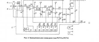
These relays are made with a 2 FORM C contact configuration and are available in three versions (Figure 4): monostable, bistable with one coil and bistable with two coils. In the dual coil version, each coil can be used independently.
Rice. 4. Versions of the magnetic system of the P2 series relays
The relays are capable of switching loads up to 2 A at voltages up to 220 V (DC) and 250 V (AC) (Table 1). The switching power is 60W, which is the standard value.
Table 1. Parameters of P2 series signal relays
| Parameter | Meaning | |
| Type of contact group | 2 FORM C (switching) | |
| Contact form | twin | |
| Contact material | AgNi (on request AgPd), Au coating | |
| Maximum direct current, A | 2 | |
| Maximum switching current, A | 2 | |
| Maximum switching voltage, V | 220 (VDC), 250 (VAC) | |
| Maximum switching power | 60 W/62.5 VA | |
| Contact resistance (10 mA/20 mV), mOhm | <50 | |
| On/off time, ms | 2 (typical), 4 (maximum) | |
| Bounce, (ms) | 1 (typical), 3 (maximum) | |
| Number of switching operations (electrical wear resistance of contacts) | 12 V/10 mA | typical 5×10⁷ |
| 6 V/100 mA | typical 1×10⁷ | |
| 60V/500mA | typical 5×10⁵ | |
| 30 V/1000 mA | typical 1×10⁶ | |
| 30V/2000mA | typical 2×10⁵ | |
| Mechanical wear resistance of contacts | typical 1×10⁸ | |
| Initial dielectric strength, Vrms | between open contacts | 1000…1500 |
| between contacts and coil | 1500 | |
| Operating temperature, °C | -40…85 | |
| Degree of dust and moisture protection | IP67 | |
| Overall dimensions, LxWxH, mm | 14.5x7.2x10.4 | |
There is a wide choice of control coils with a nominal voltage of 3...24 V and a control power of 140 mW. The bistable version with one coil has a control power of 70 mW.
The P2 series is available in three terminal designs (Figure 5) - both through-hole and surface-mount.
Rice. 5. Options for P2 series relay outputs
The most common versions of the P2 series relays are supported in the warehouse of the official distributor of TE Connectivity, COMPEL company (Table 2).
Table 2. P2 series relay stock items
| Name | Catalog number | Installation | Coil | Number of coils | Contact configuration | Magnetic system |
| V23079A2008B301 | 6-1419120-6 | THT | 3 VDC | 1 | 2 FORM C | Monostable |
| V23079D1008B301 | 6-1393788-1 | SMT | ||||
| V23079A1001B301 | 1393788-3 | THT | 5 VDC | |||
| V23079D1001B301 | 5-1393788-5 | SMT | ||||
| V23079A2003B301 | 3-1393789-7 | THT | 12 VDC | |||
| V23079A1003B301 | 1-1393788-1 | THT | ||||
| V23079D1003B301 | 5-1393788-7 | SMT | ||||
| V23079A1005B301 | 1-1393788-6 | THT | 24 VDC | |||
| V23079G1005B301 | 7-1393788-8 | SMT | ||||
| V23079C1108B301 | 5-1393788-3 | THT | 3 VDC | Bistable | ||
| V23079J1108B301 | 2-1393789-9 | SMT | ||||
| V23079B1201B301 | 3-1393788-3 | THT | 5 VDC | 2 | ||
| V23079J1101B301 | 2-1393789-5 | SMT | 1 | |||
| V23079C1103B301 | 4-1393788-8 | THT | 12 VDC | |||
| V23079B1203B301 | 3-1393788-6 | THT | 2 | |||
| V23079J1103B301 | 2-1393789-7 | SMT | 1 | |||
| V23079B1205B301 | 3-1393788-7 | THT | 24 VDC | 2 | ||
| V23079J1105B301 | 2-1393789-8 | SMT | 1 |
Selecting the right relay from the P2 series is quite simple thanks to the wide range of products. More modern are the IM series relays.
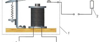
Operating principle
Essentially, a relay is an electromagnet. When control voltage is applied to the coil, the rod attracts the armature, thus switching the circuit.
There are three types of relays:
- with normally closed contacts;
- with normally open;
- throwing over.
When a control signal is applied to a device with normally closed connectors, they open; if there is no signal, they close. For relays with open connectors, the opposite is true. There is voltage on the winding, the terminals close, but when there is no voltage, it opens. In flip-over models there are two sets of connectors, one normally closed and the other normally open. They have a common terminal. When current is applied to the winding, the contacts switch from one position to another.
IM Series Signal Relays
The IM series relays represent the latest, fourth generation of signal relays. Their main advantage is their miniature dimensions and improved insulation and performance parameters. IM series relays are used in communications and telecommunications systems, office and medical equipment, automation and signaling, in instrumentation and low-power interface circuitry, consumer electronics, etc. This type is used in equipment with minimal energy consumption in StandBy mode. Relays of this series meet the requirements of standards for 4G telecom equipment.
Currently there are six versions: monostable versions 1 FORM A, 1 FORM B, 2 FORM A, 2 FORM B; bistable versions 1 FORM C, 2 FORM C.
Compared to the P2 series, the coil-to-contact insulation strength is increased to 1800 V, and the typical turn-on and turn-off time is reduced to 1 ms (Table 3).
Table 3. Parameters of IM series signal relays
| Parameter | Type | ||||||
| I.M. | IMA | IMB | IMC | IMD | IME | ||
| Type of contact group | bistable 2 FORM C | 1 FORM A | 1 FORM B | bistable 1 FORM C | 2 FORM A | 2 FORM B | |
| Contact form | twin | ||||||
| Contact material | PdRu, Au coating. Version “D” AgNi, Au coating | ||||||
| Maximum direct current, A | 2 (5 for version "D") | ||||||
| Maximum switching current, A | 2 (5 for version "D") | ||||||
| Maximum switching voltage, V | 220 (VDC), 250 (VAC) | ||||||
| Maximum switching power | 60 W/62.5 VA | ||||||
| Contact resistance (10 mA/20 mV), mOhm | <50 | <100 | <50 | ||||
| On/off time, ms | 1 (typical), 3 (maximum) | ||||||
| Blink, ms | 1 (typical), 5 (maximum) | ||||||
| Number of switching operations (electrical wear resistance of contacts) | ≤30 mV ≥10 mA | more than 2.5×10⁶ | |||||
| 125 V (DC)/0.24 A – 30 W | more than 5×10⁵ | ||||||
| 220 V (DC)/0.27 A – 60 W | more than 1×10⁵ | ||||||
| 250 V (AC)/0.25 A – 62.5 V/A | more than 1×10⁵ | ||||||
| 30 V (DC)/1 A – 30 W | more than 5×10⁵ | ||||||
| 3 V (DC)/2 A – 60 W | more than 1×10⁵ | ||||||
| Mechanical wear resistance of contacts | more than 1×10⁸ | ||||||
| Initial dielectric strength (for standard version), Vrms | between open contacts | 1000…2500 | |||||
| between contacts and coil | 1500…4000 | ||||||
| Operating temperature, °C | -40…85 | ||||||
| Degree of dust and moisture protection | IP67 | ||||||
| Overall dimensions, LxWxH, mm | 10x6x5.65 | ||||||
Coils are available in three versions: standard, high sensitivity and high sensitivity. The rated voltage range is 1.5…24 V. Control power varies from 50 to 200 mW for different options.
TE Connectivity offers all standard housing and termination options for both through-hole and surface mount applications (Figure 6).
Rice. 6. Housing options for IM series relays
The most popular versions of IM relays are supported in the COMPEL warehouse and are shown in Table 4.
Table 4. Stock items of IM series relays
| Name | Catalog number | contact Group | Magnetic system | Coil, V | Coil version | Type of terminals |
| IM46GR | 6-1462037-7 | 2 Form C | bistable | 12 | standard | SMT gull wing |
| IM41TS | 5-1462037-3 | 3 | THT standard | |||
| IM23GR | 2-1462039-9 | monostable | 5 | hypersensitivity | SMT gull wing | |
| IM22TS | 2-1462039-8 | 4.5 | THT standard | |||
| IM21GR | 2-1462039-6 | 3 | SMT gull wing | |||
| IM13GR | 1462039-4 | 5 | SMT gull wing | |||
| IM07TS | 3-1462037-0 | 24 | standard | THT standard | ||
| IM07GR | 4-1462037-7 | 24 | SMT gull wing | |||
| IM07JR | 4-1462037-8 | 24 | SMT J-leg | |||
| IM06TS | 2-1462037-7 | 12 | THT standard | |||
| IM06NS | 1-1462038-6 | 12 | THT narrow | |||
| IM06GR | 2-1462037-3 | 12 | SMT gull wing | |||
| IM05TS | 2-1462037-2 | 9 | THT standard | |||
| IM05GR | 3-1462037-4 | 9 | SMT gull wing | |||
| IM03TS | 1-1462037-8 | 5 | THT standard | |||
| IM03GR | 1-1462037-4 | 5 | SMT gull wing | |||
| IM01TS | 1462037-4 | 3 | THT standard | |||
| IM01GR | 1462037-1 | 3 | SMT gull wing |
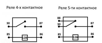
Functionality check
On the body of each relay there is a diagram with contact numbers and control voltage rating. A rectangle with pins 85 and 86 means a coil. Therefore, when measuring winding parameters, you need to connect to them. Other pins numbered 30, 87 and 87a (88) are the switching key for the external circuit.
It is convenient to use a digital multimeter as a tester for regulator relays and any other electromagnetic relay. This is because it can measure current, voltage and resistance.
Since the performance of the device depends primarily on the health of the winding, the test begins with measuring the coil resistance. Its values range from several tens of ohms to several hundred ohms.
To do this, switch the multimeter to resistance measurement mode. We connect measuring probes to pins 85, 86 and take readings. If the resistance is within normal limits, then you need to check the condition of the controlled outputs. In a relay with normally closed contacts 30 and 87, when measuring the resistance between them, the multimeter should show 0 Ohm. With normally open pins 30 and 87 the resistance between them should be infinity. When the control voltage is applied to the coil terminals 85 and 86, everything should change exactly the opposite.
Sometimes only the actuation current is known, then the coil resistance is measured. After this, the multimeter readings are multiplied by the operating current, and the control action of the winding is obtained. Then, by applying the calculated voltage, you can check the contact group, as described above.
Only AC voltage can be applied to the AC relay coil.
After checking the relay, if there is a need and the ability to adjust the contacts, do so. Otherwise, replace the entire device. Its installation and removal must be carried out with the device's power turned off.
Literature
- Petrakov V. AXICOM: a new generation of telecommunications and signal relays. Components and Technologies No. 8, 2002;
- Melashchenko A. History of the creation and development of relays. Electronic components No. 9, 2004;
- Presentation. AXICOM. Telecom-, Signal and RF Relays. IM Relays. Tyco Electronics, 2008;
- Automotive, General Purpose and Signal Relays. Definitions. Tyco Electronics, 2012;
- Presentation. Telecom – & Signal Relays. Tyco Electronics, 2012;
- Documentation www.te.com.
Obtaining technical information, ordering samples, ordering and delivery.
•••
Switch for impulse relay
Obviously, there can be many keys connected in parallel, pressing which performs the same function. To control a pulse relay, a switch is used that has a contact that opens independently under the influence of a spring - a button with a normally open (open) non-latching contact. By installing these switches in different places in a large room, you can turn on the lighting by pressing a key at the entrance and turn it off by closing the exit door. If at this time someone else is inside, then he will not need to make his way through the entire hall in the dark - just go to any nearby switch and restore the lighting.
Pulse relay in section