Concept of an asynchronous electric motor
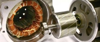
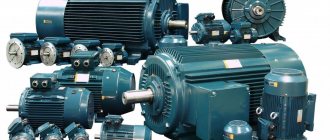
As can be seen in the photo of an asynchronous motor, such a unit is an electric machine, the purpose of which is to convert electricity into mechanical energy. In other words, such equipment, consuming electric current, produces torque. It is this that allows you to rotate many units.
The name "asynchronous" means "non-simultaneous". If you study the description of asynchronous motors, you will notice that in such devices the rotor rotates at a lower frequency than the electromagnetic field of the stator.
This lag or, as it is also called, slip can be calculated using the following formula:
S = (n1 - n2)/ n1 - 100%, where
n1 – frequency of the stator electromagnetic field;
n2 – shaft rotation frequency.
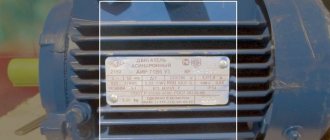
Motor marking
To simplify the connection process and selection of an asynchronous 3-phase electric motor circuit, each of them has appropriate markings. It specifies the following characteristics :
- torque;
- power;
- maximum rotation speed;
- cosφ.
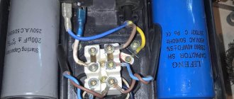
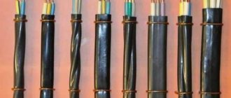
Also in the encrypted marking there is an indication of the type of motor and the number of poles. They must be taken into account when choosing a motor for certain needs. And to facilitate the connection process, all ends are brought together into a terminal box, where they are labeled as follows:
If the motor is connected to a 380 V network with a linear winding voltage of 220 V, then its winding circuit must be a triangle . But if the motor is connected to a standard 380V network, then the winding circuit must be a star.
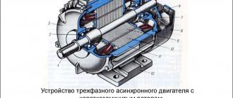
Structural solution of an asynchronous type electric motor
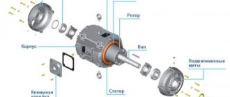
Stator, rotor, bearing shields and bearings, fan, terminal box - all these are structural elements of an asynchronous motor.
The stator is a stationary structural part on which the winding is located. It is she who creates the electromagnetic field.
The rotor is the movable component of the device. It is here that an electromagnetic moment is created, which promotes the movement of both the rotor itself and the actuator.
The cores of the two elements described above are made of electrical steel with a thickness of 1/2 mm. Insulation must be present: on the stator, its role is played by the varnish film, and on the rotor, by scale. The rotor winding is most often made of aluminum.
Today, two types of asynchronous electric machines are produced - single- and three-phase. As for the latter, they are divided into:
Design of an asynchronous motor IM
Electrical Machines › AC Electrical Machines
A traditional three-phase asynchronous motor (IM) is an electrical machine consisting of two main parts: a stationary stator and a rotor rotating on the motor shaft.
The motor stator consists of a frame into which the so-called electromagnetic stator core is pressed, including a magnetic core and a three-phase distributed stator winding. The purpose of the core is to magnetize a machine or create a rotating magnetic field.
Regardless of the type of electric motor, the stator cores (magnetic core) are made of sheets of electrical steel 0.5 mm thick (for low-power machines, in some cases 0.65 mm thick) Fig. 1. The sheets are insulated from each other either by oxidation or varnishing, or steel with an electrical insulating coating is used. The magnetic core represents a low magnetic resistance for the magnetic flux created by the stator winding, and due to the magnetization phenomenon, this flux is enhanced.
Rice. 1 Stator magnetic circuit
A distributed three-phase stator winding is placed in the grooves of the magnetic core. In the simplest case, the winding consists of three phase coils, the axes of which are shifted in space relative to each other by 120°. Phase coils are connected to each other according to star or triangle circuits (Fig. 2).
Fig. 2. Connection diagrams for the phase windings of a three-phase asynchronous motor in star and delta
The motor rotor consists of a magnetic circuit, also made of stamped steel sheets, with grooves made in it, in which the rotor winding is located. There are two types of rotor windings: phase and short-circuited .
With a wound rotor, a three-phase winding is usually placed in the slots, which is connected in a star or delta pattern and leads out to three slip rings located on the motor shaft. Contact rings with brushes mounted on them are used to turn on the ballast rheostat. This allows, by changing the rotor resistance, to regulate the motor rotation speed and limit starting currents.
The most widely used is the short-circuited winding of the “squirrel cage” type. The rotor winding of large engines includes brass or copper rods, which are driven into the grooves, and short-circuit rings are installed at the ends, to which the rods are soldered or welded. For serial asynchronous motors of low and medium power, the rotor winding is made by die casting of an aluminum alloy. In this case, rods 2 and short-circuit rings 4 with fan wings are simultaneously cast in the rotor package 1 to improve engine cooling conditions, then the package is pressed onto shaft 3. (Fig. 3). Short-circuited rotors of electric motors with increased starting torque are made with a double squirrel cage, and also deep grooved. The section taken in this figure shows the profiles of the grooves, teeth and rotor rods.
Rice. 3. Rotor of an asynchronous motor with a squirrel-cage winding
A critical structural element of asynchronous electric motors is the gap between the stator and the rotor. The size of the gap affects energy and vibroacoustic indicators, the use of active materials and the reliability of electric motors. When the gap is reduced, the reactive component of the no-load current decreases and, consequently, the power factor of the electric motor increases; at the same time, magnetic scattering increases, and consequently, the inductive reactance of the electric motor; additional losses increase, the actual efficiency of the electric motor decreases and the heating of the windings increases; the level of noise and vibration of the magnetic connection increases, the load on the shaft and bearings increases due to the force of magnetic attraction; there is a danger of the rotor touching the stator and thereby reducing the reliability of the electric motor. In asynchronous electric motors, the size of the air gap ranges from 0.2 to 2 mm.
A general view of the 4A series asynchronous motor is shown in Fig. 4. Rotor 5 is pressed onto shaft 2 and mounted on bearings 1 and 11 in the stator bore in bearing shields 3 and 9, which are attached to the ends of stator 6 on both sides. A load is attached to the free end of shaft 2. At the other end of the shaft, a fan 10 is mounted (an enclosed ventilated motor), which is closed by a cap 12. The fan provides more intensive heat removal from the engine to achieve the appropriate load capacity. For better heat transfer, the frame is cast with ribs 13 over almost the entire surface of the frame. To attach the engine to the foundation, frame or directly to the mechanism being driven, the frame is provided with paws 14 with holes for fastening. Flanged motors are also available. For such machines, a flange is made on one of the bearing shields (usually on the shaft side), allowing the motor to be connected to the working mechanism.
Rice. 4. General view of the 4A series asynchronous motor
Motors are also available with both feet and a flange. The installation dimensions of the engines (the distance between the holes on the feet or flanges), as well as their heights of the rotation axis, are standardized. The height of the rotation axis is the distance from the plane on which the engine is located to the axis of rotation of the rotor shaft. Heights of the rotation axes of low-power engines: 50, 56, 63, 71, 80, 90, 100 mm.
Devices with wound rotor
The phase rotor consists of a shaft with a core equipped with 3 windings. Some of the ends, when connected, form a star, and the rest are attached to slip rings that supply electric current.
The widest area of use is for three-phase electric motors with a squirrel-cage rotor.
Repair
Repair work on the entire device is carried out in order to restore its functionality and performance. Sometimes some parts need to be replaced. For example, when the stator heats up for various reasons, carbon deposits may form on the armature structure of the electric motor.
The sequence of steps is then as follows:
- engine dismantling;
- cleaning work;
- disassembly of all components;
- restoration of damaged parts;
- painting;
- assembling the engine and testing it under load conditions.
If the equipment is of the phase type, then repair work is required on its individual components, including the brush-commutator unit.
If the rod has cracks, it must be restored or replaced. This is done like this: at the site of the crack, an incision is made and holes are drilled from the point of this incision to the end of the closing ring. The part that was drilled is filled with copper alloy.
Do not forget about checking the engine for open circuits and short circuits. The rotor and stator resistance are checked using an ohmmeter, while checking the technical specifications in the operating instructions. However, the device must be extremely sensitive due to the tendency of resistance to zero in the windings of powerful motor models.
Principle of operation
The operating principle of an asynchronous electric motor with a squirrel-cage rotor is as follows: when current is supplied to the stator windings, a magnetic flux arises, which, when rotating, contributes to the generation of current and a magnetic field in the rotor. The rotor and stator fields, interacting with each other, set the engine rotor in motion.
Equipment with a wound rotor has a similar operating principle. Therefore, we will not re-describe the entire operating process of the device.
Electric motors
An electric motor is an electrical machine in which electrical energy is converted into mechanical energy.
The operation of electric motors is based on the principle of electromagnetic induction. They are divided into DC motors and AC motors. In turn, DC motors are divided according to the method of phase switching, commutator motors and valve motors. By type of excitement. AC motors are divided according to the principle of operation into synchronous and asynchronous motors. By number of phases. An electric machine consists of a stationary part - a stator or inductor, and a moving part - a rotor or armature. The rotor of an asynchronous motor can be squirrel-cage or phase. The main programs for working with drawings published on the site: • KOMPAS-3D • AutoCAD • SolidWorks • T-FLEX CAD
Contents: 3D assembly, drawings, specifications
Contents: Overall 3D model of the engine
Composition: One piece model
Photo of an asynchronous electric motor
Reinforcing shears (bolt cutters): types, characteristics, main differencesHow a voltage control relay works: the principle of operation of the protection and the nuances of connecting a control relay for a house or apartment
What is a pulse relay: principle of operation, types, description of devices and connection diagrams. 155 photos of pulse-type relays and video installation instructions
Did you like the article? Share
0
The manufacture of such electric motors is carried out in a very wide power range, where the device rating can be only a few watts, or can have a power of tens of megawatts. Let's look at the operating principle of all these schemes.
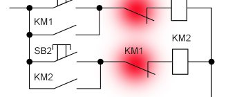
Typical circuits of open-loop electric motor control systems After opening the contact of the RTD time relay, the circuit returns to its original state, the engine smoothly stops. The ends of a three-phase winding can be: connected inside the electric motor, three wires coming out of the motor, six wires coming out of the motor, six wires coming out of the box, six wires coming out of the box, three wires coming out of the box.
I will know where to go if I need information on starting the engine. When the rotor is stationary, the magnetic fields Fa and Fv create torques M1 and M2 that are equal in magnitude but opposite in sign. The winding creates a magnetic flux stationary in space.
When a single-phase motor overcomes the rated load, a slight slip is created with the main share of the direct torque Mpr. In this case, electromagnetic starters with coils for voltage of 48, 36 or 24 V are used. The main positive characteristics of squirrel-cage asynchronous electric motors are their high reliability, low weight, compactness, and longer service life than internal combustion engines of similar power. Such a diagram is shown in Fig.
Rheostatic starting of an asynchronous motor with a short-circuit rotor.
It is possible to use a step-down transformer to reduce the voltage in the control circuit. An animation of the processes occurring in the diagram is shown below. The considered circuit is the basis for constructing control circuits for electric motors of two-speed feed conveyors, cross-cutting units, sorting conveyors, etc.
Such circuits are also often supplemented with various contacts of relays, switches, switches and sensors. Reversible motor connection diagram.
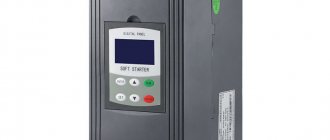
These engines are easy to design, maintain and repair. Start A rotating magnetic field passing through a squirrel-cage rotor. A magnetic moment acting on the rotor. You may also notice that the rotor bars are tilted relative to the axis of rotation. The drive can have two speeds. Therefore, you may need to use some kind of soft start device to get rid of inrush currents. This is done in order to reduce the higher harmonics of the EMF and get rid of torque ripple. asynchronous motor switching diagrams