NORMATIVE REFERENCES
This document uses references to the following regulatory documents:
- Rules for the technical operation of consumer electrical installations, 1992;
- Safety regulations for the operation of consumer electrical installations, 1994;
- Electrical Installation Regulations 1986;
- Standards for testing electrical equipment and devices of consumer electrical installations, 1982;
- Electrical Test Code 1978;
- GOST 26567-85. Semiconductor power converters. Test methods;
- GOST 3345-76. Cables, wires and cords. Method for determining electrical insulation resistance;
- GOST 3484-88. Power transformers. Electromagnetic testing methods;
- GOST 3484.3-83. Power transformers. Methods for measuring dielectric parameters of insulation.
3.DEFINITIONS
3.1. This methodology uses the terms established in GOST 3345-76, GOST 3484.3-83, GOST 3484.1-88, GOST 16504, GOST 23875.
Distribution device - a distribution device for the generator voltage of a power plant or the secondary voltage of a step-down substation of a district (enterprise) to which the networks of the district (enterprise) are connected.
Symbols and abbreviations:
- HV - high voltage windings;
- MV - medium voltage windings;
- LV - low voltage windings;
- NN1, NN2 - low voltage windings of transformers with split windings;
- R15 - fifteen second value of insulation resistance in MOhm;
- R60 - one-minute insulation resistance value in MOhm;
- PEEP - operating rules for consumer electrical installations;
- PTBEEP - safety regulations for the operation of consumer electrical installations;
- PUE - Rules for electrical installations.
MEASUREMENT PROCEDURE
4.1 Measurable indicators
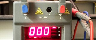
Insulation resistance is measured with megohm meters (100-2500V) with measured values in Ohm, kOhm and MOhm.
4.2 Measuring instruments
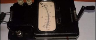
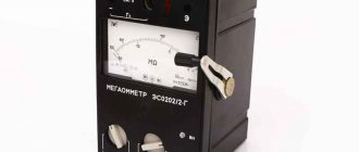
Insulation measuring instruments include megohmmeters: ESO 202, F4100, M4100/1-M4100/5, M4107/1, M4107/2, F4101. F4102/1, F4102/2, BM200/G and others, produced by domestic and foreign companies.
4.3 Qualification requirements
Trained electrical personnel who have a certificate of knowledge testing and a qualification group for electrical safety of at least 3rd, when performing measurements in installations up to 1000 V, and not lower than 4th, when measuring in installations above 1000 V, are allowed to perform insulation resistance measurements.
Persons from electrical engineering personnel with secondary or higher specialized education may be allowed to process measurement results.
Analysis of measurement results should be carried out by personnel involved in the insulation of electrical equipment, cables and wires.
Insulation Test Examples
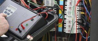
Measuring insulation on an electrical installation
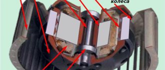
Insulation measurement on a rotating machine
Insulation measurement on tools and electric motors
Measuring insulation on a transformer
a. Between high voltage winding and low voltage winding and ground
b. Between low voltage winding and high voltage winding and ground
c. Between high voltage winding and low voltage winding
d. Between high voltage winding and ground
e. Between low voltage winding and ground
Read more about devices for testing the insulation of high-voltage cable lines in this section.
If you need professional advice on measuring the insulation resistance of electrical equipment, just send us a message!
SAFETY REQUIREMENTS
- When performing insulation resistance measurements, safety requirements must be met in accordance with GOST 12.3.019.80, GOST 12.2.007-75, Rules for the operation of consumer electrical installations and Safety rules for the operation of consumer electrical installations.
- The premises used for measuring insulation must meet the explosion and fire safety requirements in accordance with GOST 12.01.004-91.
- Measuring instruments must meet the safety requirements in accordance with GOST 2226182.
- Megger measurements may only be carried out by trained electrical personnel. In installations with voltages above 1000 V, measurements are carried out by two persons at a time, one of whom must have electrical safety ratings of at least IV. Carrying out measurements during installation or repair is specified in the work order in the line “Entrusted”. In installations with voltages up to 1000 V, measurements are carried out by order of two persons, one of whom must have a group of at least III. An exception is the tests specified in clause BZ.7.20.
- Measuring the insulation of a line that can receive voltage from both sides is permitted only if a message is received from the person in charge of the electrical installation that is connected to the other end of this line by telephone, messenger, etc. (with a reverse check) that the line disconnectors and switch are disconnected and a poster “Do not turn on. People are working."
- Before starting tests, it is necessary to make sure that there are no people working on that part of the electrical installation to which the test device is connected, to prohibit persons located near it from touching live parts and, if necessary, to set up security.
- To monitor the insulation condition of electrical machines in accordance with methodological instructions or programs, measurements with a megger on a stopped or rotating, but not excited machine can be carried out by operational personnel or, by their order, in the order of routine operation by electrical laboratory workers. Under the supervision of operating personnel, these measurements can also be performed by maintenance personnel. Tests of insulation of rotors, armatures and excitation circuits can be carried out by one person with an electrical safety group of at least III, tests of stator insulation - by at least two persons, one of whom must have a group of at least IV, and the second - not lower than III.
- When working with a megger, touching the live parts to which it is connected is prohibited. After completion of work, it is necessary to remove the residual charge from the equipment being tested by briefly grounding it. The person removing the residual charge must wear dielectric gloves and stand on an insulated base.
- It is prohibited to take measurements with a megger: on one circuit of double-circuit lines with a voltage above 1000 V, while the other circuit is energized; on a single-circuit line, if it runs in parallel with a working line with a voltage above 1000 V; during a thunderstorm or when it is approaching.
- Measuring the insulation resistance with a megger is carried out on disconnected current-carrying parts from which the charge has been removed by first grounding them. Grounding from live parts should be removed only after connecting the megger. When removing grounding, you must use dielectric gloves.
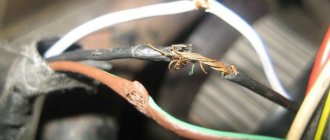
Reasons for deterioration of insulation
Local heating of contact connections also contributes to the deterioration of the insulating properties of cables . Heat, spreading through the metal core, heats the coating material, reducing its insulating properties. This applies to junction boxes and to places where conductors are connected to circuit breakers, neutral busbars, and sockets.
Insulation damage due to overheating
The housings of switching devices: switches, automatic machines, knife switches are made of insulating materials. A decrease in insulation occurs if dust, dirt, or metal filings settle on them . The reduction in insulating properties is facilitated by overheating of the housings and their charring after short circuits.
The scourge of electrical panels is humidity . Damage to pipelines, the formation of condensation, flooding of basements with distribution devices - all this leads to the appearance of water droplets between the terminals of electrical equipment, which are under different electrical potentials. Water in its pure form does not conduct electricity. But when it gets on the dirt and dust covering the housings of electrical appliances, it dissolves the substances in it, becoming a conductor of electric current. A short circuit occurs.
Damage to cable insulation during installation
The greatest risk of encountering damaged insulation occurs after installation work . The second peak of problems occurs already in operation , a certain number of years after installation. A separate type includes damage associated with improper operation of electrical appliances and wiring, flooding of the apartment by neighbors and nails driven into the route when trying to hang a picture on the wall.
CONDITIONS FOR PERFORMING MEASUREMENTS
- Insulation measurements must be carried out under normal climatic conditions in accordance with GOST 15150-85 and under normal power supply conditions or as specified in the manufacturer's data sheet - technical description for megohmmeters.
- The value of the electrical insulation resistance of the connecting wires of the measuring circuit must exceed at least 20 times the minimum permissible value of the electrical insulation resistance of the product under test.
- The measurement is carried out indoors at a temperature of 25±10 °C and a relative air humidity of no more than 80%, unless other conditions are provided for in the standards or technical specifications for cables, wires, cords and equipment.
PREPARATION FOR MEASUREMENTS
- They check the climatic conditions at the place where the insulation resistance is measured with the measurement of temperature and humidity and the compliance of the room with explosion and fire hazards to select a megger for the appropriate conditions.
- The condition of the selected megohmmeter, connecting conductors, and the operability of the megohmmeter are checked by external inspection in accordance with the technical description for the megohmmeter.
- Check the validity period of the state verification on the megohmmeter.
- The preparation of measurements of cable and wire samples is carried out in accordance with GOST 3345-76.
- When performing periodic preventive work in electrical installations, as well as when performing work on reconstructed facilities in electrical installations, the preparation of the workplace is carried out by the electrical technical personnel of the enterprise where the work is performed in accordance with the rules of PTBEEEP and PEEP.
TAKING MEASUREMENTS
The reading of the electrical insulation resistance values during measurement is carried out after 1 minute from the moment the measuring voltage is applied to the sample, but not more than 5 minutes, unless other requirements are provided for in the standards or technical conditions for specific cable products or other equipment being measured.
Before re-measurement, all metal elements of the cable product must be grounded for at least 2 minutes.
The electrical insulation resistance of individual cores of single-core cables, wires and cords must be measured:
- for products without a metal sheath, screen and armor - between the conductor and the metal rod or between the conductor and grounding;
- for products with a metal shell, screen and armor - between the conductive conductor and the metal shell or screen, or armor.
The electrical insulation resistance of multi-core cables, wires and cords must be measured:
- for products without a metal sheath, screen and armor - between each current-carrying conductor and the remaining conductors connected to each other or between each conductive conductor; residential and other conductors connected to each other and grounding;
- for products with a metal shell, screen and armor - between each current-carrying conductor and the remaining conductors connected to each other and to the metal shell or screen, or armor.
If the insulation resistance of cables, wires and cords is low and differs from the normative rules of PUE, PEEP, GOST, it is necessary to perform repeated measurements by disconnecting the cables, wires and cords from the consumer terminals and separating the current-carrying conductors.
When measuring the insulation resistance of individual samples of cables, wires and cords, they must be selected for construction lengths, wound on drums or in coils, or samples with a length of at least 10 m, excluding the length of end cuts, if in the standards or technical specifications for cables, wires and cords are not specified in other lengths. The number of construction lengths and samples for measurement must be specified in the standards or technical specifications for cables, wires and cords.
Rules for taking measurements with a megohmmeter
A megohmmeter refers to devices that measure the characteristics of electrical equipment related to determining the possibility of its safe operation . And at its conclusions during measurements there is a life-threatening voltage . Therefore, its use is possible in the following cases:
- The device must undergo metrological verification once a year.
- Only trained personnel are allowed to use the megohmmeter.
- Only a licensed electrical laboratory has the right to issue a protocol with a conclusion on the suitability of electrical wiring for further use. Measurements taken by other persons have no legal force.
If you have a megohmmeter at your disposal, then you can measure the insulation resistance only on your own initiative . We finished installing the electrical wiring for our neighbor, measured it and made sure there were no defects. But if, when connecting your neighbor’s house to the network, the energy supply organization requires a measurement protocol , your work will not be counted. The neighbor will have to call specialists and pay them money for the same work.
In kindergartens, schools, institutions and enterprises, the insulation resistance of electrical wiring is measured regularly . The results are documented in protocols required by representatives of the fire department and energy supervision. The registration documents of the laboratory that performed the measurements are attached to the protocols. Without them, they are a useless piece of paper.
Insulation resistance measurement protocol
If a fire occurs in an organization’s premises, the first thing that is required from its managers is insulation measurement protocols. If there are none, the culprits are determined automatically. The same thing happens when an employee is struck by an electric shock. Even if he himself inserted a screwdriver into the socket, holding onto its rod. If, during the investigation of an accident, an insulation measurement protocol is not discovered, problems are guaranteed for management.
However, a megohmmeter is a useful device for people involved in electrical wiring. It is better to find the defect immediately , before the arrival of specially trained persons. Otherwise, they will come again, after eliminating the defect. Laboratory personnel are not required to search for it themselves. When they return, they will force the owner to pay an additional amount for the work. Most likely, he will deduct it from your fee.
After replacing the electrical wiring in the apartment, insulation measurements are not officially required . Therefore, it doesn’t hurt to do them to reassure yourself, and in the eyes of the client, your rating will only increase in the end.
CONVERTER ISOLATION MEASUREMENT
9.1. Measurement of electrical resistance and insulation of converters is carried out in accordance with the requirements of this standard, and when exposed to climatic factors, measurement of insulation resistance is carried out taking into account GOST/16962-71.
Measuring instruments : megohmmeters and ohmmeters in accordance with GOST 16862-71.
Electrical insulation resistance is measured:
- in normal climatic conditions; at the upper value of the ambient temperature after thermal equilibrium has been established in the converter;
- at the upper value of relative humidity.
Insulation resistance is measured between electrically unconnected circuits, electrical circuits and the housing. In the specifications or design documentation for converters of specific series and types, the terminals between which the resistance should be measured and the value of the direct voltage at which this measurement is carried out are indicated. If one of the terminals or elements according to the circuit is connected to the housing, then this circuit must be disconnected for the duration of the tests. When measuring the insulation resistance of converters, the following conditions must be met:
Table 1.
| Rated circuit voltage, V | Meter voltage, V |
| Up to 100 inclusive Over 100 to 500 inclusive Over 500 to 1000 inclusive Over 1000 | 100 250-1000 500-1000 2500 |
- before testing, the converter must be disconnected from external power supplies and load;
- the input (output) terminals of the converter, capacitors connected to power circuits, as well as anode, cathode and control terminals of power semiconductor devices must be connected to each other or shunted;
- contacts of switching equipment of power circuits must be closed or bypassed;
- electrical circuits containing semiconductor devices and microcircuits must be disconnected and, if necessary, tested separately;
- The voltage of the measuring device when measuring insulation resistance, depending on the nominal (amplitude) value of the circuit voltage, is selected according to the table. 1.
If necessary, the insulation resistance is measured at higher voltages, but not exceeding the test voltage of the circuit.
Measuring the insulation resistance of converters consisting of several cabinets can be carried out separately for each cabinet.
If the insulation resistance of each cabinet and (or) structural unit of the converter is measured, then the value of the insulation resistance of each cabinet and (or) structural unit must be indicated in the specifications for converters of specific series and types.
The values of the minimum permissible insulation resistance for power cables, switches, load switches, disconnectors, valve arresters, dry-type reactors, instrument transformers, 6-10 kV indoor switchgear, AC motors, stationary, mobile and complete testing devices are given in Table. 2.
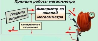
Procedure for measuring insulation resistance
Currently, the most common megaohmmeters are type M4100 (five modifications M4100/1-M4100/5). Megaohmmeters of the F. 4100 series, with electronic power supply from the mains, are designed for rated operating voltages of 100, 500, 1000 (F4101, F4102). Megaohmmeters ES-0202/1G (for 100, 250, 500 V) and ES0202/2G (500, 1000 and 2500) are no longer produced, however, megaohmmeters of type M l101 M, MS-05, MS-06 are used with great success. The minimum accuracy class of instruments is fourth. The insulation resistance of electrical installations is measured by connecting megaohmmeters to the circuit. The connection is made using flexible single-core wires. The insulation resistance of these wires, the length of which must be at least 2-3 meters, must be 100 MΩ. The ends of the wires are marked, end caps are put on them from the mega-ohmmeter side, and the opposite ends are equipped with alligator clips, and the clips are equipped with special probes or insulated handles. When measuring the insulation resistance of electrical installations, the wires “should not touch each other, the soil, grounded structures, or cable sheaths. When measuring insulation resistance relative to ground, the “z” (ground) terminals are connected to the grounded body of the device, the grounded metal sheath of the cable or to the protective ground, and the “l” (line) terminal is connected to the current conductor.”
Measuring the insulation resistance of power cables and wiring
The beginning of measuring insulation resistance begins with checking the cable for voltage - it should be absent. Grounding for 2-3 minutes removes residual charges from the current-carrying core, and you can begin to work. Dust, dirt, and other foreign substances make it difficult to accurately measure insulation resistance, so the cable must be cleared of them. Reconciliation with the manufacturer's passport gives our experts the value of the expected resistance, based on which the measurement limit is selected. After a control check - determining the readings on the megaohmmeter scales with closed and open wires - the device is allowed to operate. When the wires are open, the arrow should point to infinity, when wires are closed, to zero.
Insulation resistance measurement begins by checking each phase against ground. If the readings reveal a violation of the insulating function, the insulation of each phase is measured relative to ground, as well as between the two phases. The number of measurements varies: for a three-core cable 3-6 measurements can be taken, for a five-core cable - 4, 8 or 10. Since there are several schemes, it is necessary to indicate in the measurement certificate the scheme according to which the work was carried out.
The limit values of the megohmmeter are 15 and 60 seconds from the moment of connection to the object under study, from which the absorption coefficient, that is, the humidity of the insulation, is also calculated. If the values clearly do not correspond to the expected values, it is recommended to remove the residual voltage again by applying grounding, switch the limit and repeat the measurement. According to safety rules for measuring the insulation resistance of electrical equipment, this operation must be carried out with dielectric gloves. In addition, it is strictly recommended to follow the measurement rules specified in paragraphs. 1.7.81, 2.1.35 PUE: “Zero working and zero protective conductors must have insulation equivalent to the insulation of phase conductors”; “both on the power supply side and on the receiver side, the neutral conductors must be disconnected from the grounded parts”, “the test circuit... differs only in the number of measurements (4 or 8, instead of 3 or 6) and in the absence of the need to use a clamp “ Screen" on megohmmeters"; “measurement of the insulation resistance of power and lighting electrical wiring is carried out with the voltage removed, switches turned off, fuses removed, electrical receivers, devices turned off, and electric lamps turned out.”
Measuring the insulation resistance of power electrical equipment
As with cable insulation, temperature is of great importance for electrical devices and machines. Thus, class A insulation is characterized by an increase in insulation resistance by one and a half times with a decrease in temperature for every 10 degrees. Class B insulation doubles the resistance for every 10 degree temperature increase. Therefore, temperature limits have been established for measuring the insulation resistance of electrical equipment, and special coefficients have been developed: for electrical machines - Kt, for transformers - Kz, which can be viewed in the table. Standards for insulation resistance are given in two documents: for already operating installations - in PTEEP, for those in the process of commissioning - in PUE.
In addition to the wiring insulation, when measuring the insulation resistance of electrical equipment, the resistance relative to the housing and external metal parts is also measured when the engine is turned off. As a rule, such measurements are carried out for portable power tools. If the instrument body is made of dielectric, it is wrapped in metal foil before measurement and connected to a ground loop. For portable transformers, additional measurements of the insulation resistance between the housing and the windings are carried out. And also between the windings, while the secondary winding must be short-circuited to the housing. Electrical equipment insulation resistance measurements include measurements of the insulation resistance of circuit breakers and residual current devices.
The measurement rules are regulated by GOST R 50345-99 and GOST R 50030.2-99, which consider different types of RCDs and AVs, the first establishes measurement rules for devices with a minimum insulation resistance of 2 or 5 MOhm (items 1, 2 and 3 - accordingly), the second document establishes measurement rules for devices with a minimum insulation resistance of at least 0.5 MOhm. According to GOSTs, the measurement of insulation resistance of electrical equipment of this type is carried out:
- Between each pole terminal and the opposite pole terminals connected to each other when the switch or RCD is open;
- Between each opposite pole and the remaining poles connected to each other when the switch or RCD is closed;
- Between all the interconnected poles and the body, wrapped in metal foil.
When working with measuring instruments in terms of measuring the insulation resistance of RCDs and AVs, it is necessary to remember the difference in the parameters of the output voltage and the highest value of the measured resistance for different types of measuring instruments: only in the F4100 family of megohmmeters there are five different types.
All types of measurements of insulation resistance of electrical equipment are carried out by our specialists in strict accordance with the requirements of GOST R, PTEEP, PUE, OiNIE and other regulatory documents, documented in protocols with all necessary attachments. The electrical measuring laboratory has all the permits for carrying out the types of work.
PROCESSING OF MEASUREMENT RESULTS
10.1. If the measurement for cable products was carried out at a temperature different from 20 °C, and the value of electrical insulation resistance required by standards or technical specifications for specific cable products is normalized at a temperature of 20 °C, then the measured value of electrical insulation resistance is recalculated to a temperature of 20 °C according to formula:
R20=KRt,
where R20 is the electrical insulation resistance at a temperature of 20 °C, MOhm; Rt—electrical insulation resistance at measurement temperature, MOhm; K is the coefficient for reducing the electrical insulation resistance to a temperature of 20 °C, the values of which are given in the appendix to this standard.
In the absence of conversion factors, the arbitration method is to measure the electrical resistance of the insulation at a temperature of (20±1)°C.
10.2. The recalculation of the electrical insulation resistance R for a length of 1 km should be carried out according to the formula:
R=R20L, where R20 is the electrical insulation resistance at a temperature of 20 °C, MOhm; L is the length of the tested product without taking into account the end sections, km.
Coefficient K for reducing the electrical resistance of insulation to a temperature of 20 °C.
The error in the insulation resistance value is calculated according to the recommendations specified in the technical descriptions and operating instructions for megohmmeters, taking into account external influencing factors.
REGISTRATION OF MEASUREMENT RESULTS
The measurement results are included in test reports for cables up to and above 1000 V, as well as in protocols for preventive adjustment work on relay protection and electrical equipment.
Table 2.
| Name of insulation resistance measurements | Standardized value, Mohm, not less | Megger voltage, V | Directions |
| Power cables above 1000 V | Not standardized | 2500 | When testing with increased voltage, the insulation resistance R60 must be the same before and after the test |
| Power cables up to 1000V | 1 | 1000 | |
| Oil switches: | |||
| 1. Movable and guides | |||
| parts made of organic material. 3-10kV, | 300 | 2500 | |
| 15-150kV | 1000 | ||
| 220kV | 3000 | ||
| 2. Secondary circuits, including turning on and off coils. | 1 | 1000 | |
| H.Load switches: measuring the insulation resistance of the closing and disconnecting coils | 1 | 500-1000 | The insulation resistance of the power section is not measured, but is tested with increased power frequency voltage |
| 4. Disconnectors, short circuiters and separators: | Produced only at positive ambient temperatures | ||
| 1.Leash rods made | |||
| from organic materials | |||
| 3-10kV | 300 | 2500 | |
| 15-150kV | 1000 | 2500 | |
| 220kV | 3000 | 2500 | |
| Measuring the voltage resistance of a valve arrester element: | The resistance of the arrester or its element should differ by no more than 30% from the measurement results | ||
| above 3 kV and above | 2500 | ||
| less than 3 kV | 1000 | at the manufacturer or previous measurements during operation | |
| Dry reactors. Measuring winding resistance relative to mounting bolts | 0,5 | 1000-500 | After major renovation. |
| 0,1 | 1000-500 | In use | |
| Voltage transformers above 1000V: | Not standardized. | 2 500 | When assessing the condition of the secondary windings, you can focus on the following average resistance values of a serviceable winding: for built-in CTs - 10 MOhm, for remote CTs - 50 MOhm |
| primary windings, secondary windings | Not lower than 1 together with connected circuits | 1000 | |
| Switchgear 3-10 kV: primary circuits secondary circuits | 300 | 2 500 | Measurement is performed with fully assembled circuits |
| 1 | 500-1000 V | ||
| AC motors above 660 V | Not | Must be taken into account when drying is required. | |
| normalized | 2500 | ||
| exchange stator. up to 660 V | 1 | 1000 | |
| The stator windings of the electric motors for voltages above 3000 V or power more than 3000 kW | R60/R15 | 2500 | Produced for synchronous motors and asynchronous motors with a wound rotor with a voltage of 3000 V and above or a power above 1000 kW |
| I don’t standardize | 1000V | ||
| Rotor windings | yes | ||
| Stationary, mobile, portable complete testing installations. | Not standardized | 2500 | |
| Measuring the insulation of circuits and equipment e.g. above 1000V. | |||
| Circuits and equipment for voltages up to 1000 V | 1 | 1000 | |
| DC machines: | Winding insulation resistance | ||
| measurement of insulation of windings and bands up to 500V, | 0,5 | 500 | measured relative to the body, and bandages - relative to the body and |
| above 500V | 1 000 | windings held by it together with the circuits and cables connected to them | |
| Power and lighting wiring | 0,5 | 1000 | |
| Switchgears, boards and conductors | 0,5 | 1000 | |
| Secondary control, protection and automation circuits DC buses | 1 | 500-1000 | |
| 10 | 500-1000 | ||
| Each connection of secondary circuits and power supply circuits of switch drives | 1 | 500-1000 | |
| Control circuits, protection, automation, telemechanics, excitation of DC machines. current to voltage 500-1000V connected to the main switchgear circuits | 1 | 500-1000 | The insulation resistance of circuits with voltages up to 60 V, normally powered from separate sources, is measured with a 500 V megohmmeter and must be at least 0.5 MOhm |
| Circuits containing devices with microelectronic elements: | |||
| above 60 V | 0,5 | 500 | |
| 60 and below | 0,5 | 100 |
40236
Bookmarks
Comment 1
Comments 1
3. Characteristics of the measured quantity, standard values of the measured quantity.
3.1. The object of measurement is electrical equipment and wiring with voltages up to and above 1000 V
3.2. The measured quantity is the insulation resistance.
3.3.
The measured insulation resistance of electrical equipment with voltages up to 1000 V must not be lower than the minimum permissible value given in the table. Minimum permissible values of insulation resistance of elements of electrical networks with voltages up to 1000 V
| Item name | Megger voltage, V | Insulation resistance, MOhm | Note |
| Electrical products and devices for rated voltage, V: | Must comply with manufacturers' instructions, but not less than 0.5 | When taking measurements, semiconductor devices in products must be shunted | |
| up to 50 | 100 | ||
| over 50 to 100 | 250 | ||
| over 100 to 380 | 500-1000 | ||
| over 380 | 1000-2500 | ||
| Switchgears, boards and conductors | 1000-2500 | at least 1 | Measurements are taken on each section of the switchgear |
| Electrical wiring, including lighting networks | 1000 | not less than 0.5 | Insulation resistance measurements in particularly hazardous rooms and outdoor installations are carried out once a year. In other cases, measurements are made once every 3 years. When making measurements in power circuits, measures must be taken to prevent damage to devices, especially microelectronic and semiconductor devices. In lighting networks, lamps must be unscrewed, sockets and switches connected. |
| Secondary circuits of switchgears, power supply circuits for drives of switches and disconnectors, control circuits, protection circuits, automation, telemechanics, etc. | 1000-2500 | at least 1 | Measurements are made with all connected devices (coils, contactors, starters, switches, relays, instruments, secondary windings of voltage and current transformers) |
| Cranes and elevators | 1000 | not less than 0.5 | Produced at least once a year |
| Stationary electric stoves | 1000 | at least 1 | Performed when the stove is heated at least once a year |
| DC buses and voltage buses on control panels | 500-1000 | at least 10 | Produced with disconnected circuits |
| Control, protection, automation, telemechanics, excitation circuits for DC machines with a voltage of 500-1000 V connected to the main circuits | 500-1000 | at least 1 | The insulation resistance of circuits with voltages up to 60 V, powered from a separate source, is measured with a megohmmeter for a voltage of 500 V and must be at least 0.5 MOhm |
| Circuits containing devices with microelectronic elements designed for operating voltage, V: | |||
| up to 60 | 100 | not less than 0.5 | |
| above 60 | 500 | not less than 0.5 |