Insulation resistance, process physics
The most common type of measurement in my practice is measuring insulation resistance. This type of measurement can be made on a cable (before and after high-voltage tests), the stator winding of a turbogenerator, an electric motor, a transformer; even in relay protection, circuits have to be constantly tested. In general, on any electrical equipment that has insulation, it is necessary to monitor its value and identify possible inconsistencies in order to prevent possible adverse consequences for the equipment.
Let's talk about the physical model of insulation resistance. More details about classes and types of insulation will be written in a separate article. Let us clarify that the factors that spoil the insulation are the currents flowing in the equipment and overcurrents (starting, short-circuit currents). In this material I will focus on the insulation equivalent circuit. This will be a circuit consisting of two active resistances and two capacitors. This means that we have:
- C1 - geometric capacity
- C2- absorption capacity
- R1 – insulation resistance
- R2 – resistance, losses in which are caused by absorption currents
Why do you need to know this? Well, I don’t know, maybe to show off in front of people who don’t know these basics. Or, to understand the nature of the passage of direct current through insulation.
The first circuit consists of capacitance C1. This capacity is called geometric; it is characterized by the geometric characteristics of the insulation and its location relative to the ground. This capacitance is discharged instantly when the insulation is grounded after the test. That very same spark when applying grounding to the phase under test after the experiment.
The second circuit contains two elements - capacitance C2 and active resistance R2. This circuit simulates losses when AC voltage is applied to the insulation. R2 characterizes the structure and quality of the insulation. The more frayed the insulation, the lower the R2 value. Capacity C2 is called absorption capacity. This capacitance is charged, when a constant voltage is applied, not instantly, but in a time proportional to the product of R2 by C2. The better the dielectric properties of the insulation, the longer it will take the capacitance C2 to charge, because the value of R2 will be greater for healthy insulation. In general, this capacitance answers the question why, after a spark, it is necessary to keep the grounding on the test core for a couple of minutes. It discharges slowly and does not charge instantly.
The third branch consists of active resistance R3, which characterizes the insulation leakage current and losses. The current increases when the insulation is moistened and is proportional to the insulation area and inversely proportional to the insulation thickness. Here is an electrical model of insulation.
Characteristics that an insulation resistance tester must have
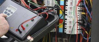
When checking
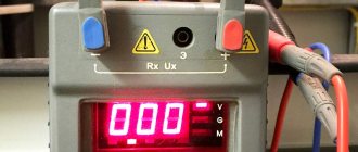
To determine the quality and current state of the insulation, a special device is used, which is called a megger. It allows you to measure indicators in millions of ohms, which was the reason for choosing its name.
A standard insulation resistance tester, which is used to test lines with operating voltages up to 1 kV, must operate with a test current of 250-1000 Volts.
If it is intended to examine high-voltage installations, the insulation resistance measurement should be carried out using a voltage of 2500 Volts. In addition, a feature of the device must be the presence of documents confirming the state registration of this model, as well as passing mandatory annual verification.
History of the development of the megohmmeter
Let's talk about the history of the development of megaohmmeters. Where did this name come from? Probably due to the name of the measured quantity. By the way, a megohmmeter is also called a meger, or they say to measure the chain. Sound familiar? It turns out, and you probably knew this, the name comes from the name of an ancient measuring equipment company called Megger. This company appeared back in the 19th century, and the first testers were produced back in 1951.
The first megaohmmeters, then still meggers, had handles. You turn the knob, a constant voltage is generated, and you carry out the tests. It was necessary to spin at a frequency of 120 rpm. However, not everyone could spin for a long time. After all, measurements must be made for one minute to determine the absorption coefficient. Therefore, science has stepped forward, and similar megohmmeters have appeared, but with mains power and a voltage supply button. Holding a button is much more convenient than turning a knob. However, there is an inconvenience in the sense that you need to find an outlet.
However, progress did not stop there, and electronic megohmmeters appeared. They are already backlit, it is not necessary to hold the voltage button throughout the test, however, when testing the cable, the residual capacity can burn the device (well, I haven’t checked, but some engineers say so).
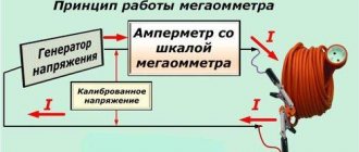
What measuring instruments can be used
At first glance, it might seem that it would be logical to use a multimeter for this purpose. However, in most cases, the current that passes through the wiring is so small that this meter cannot accurately measure it. In such cases, it is convenient to use a megohmmeter, with which you can measure voltage and electric current. These devices can be analog or digital. Based on Ohm's law, the resistance value is determined from the data obtained.
The operating principle of the device can be explained using the example of an electromechanical version of a megohmmeter.
A hand generator (a) is used to supply current. In fact, we are talking about a handle that needs to be turned to generate energy. In this case, it is necessary that the rotation speed be at least two revolutions per second. An analog ammeter (b) is connected to the arrow of the device.
The instrument scale (c) is graduated to indicate the resistance value. The circuit uses several resistors (d). How many there are depends on the model of the device. There is a measurement scale switch (e). In this case, you can measure resistance in Ohms or MegaOhms. There are input terminals (f) to which wires are connected.
One of the advantages of such a device is that it does not require additional power, since the current obtained using a hand-held generator is used for measurements. However, when using it, it is necessary to take into account its inherent disadvantages:
- To ensure the required measurement accuracy, the device must remain stationary. However, this is difficult to achieve when rotating the handle.
- Accuracy is affected by how evenly the handle is rotated. It is necessary to ensure a constant voltage supply during measurement. Compliance with this condition is not always possible.
- It is difficult to measure insulation resistance with such a device alone. Therefore, two people usually work with it: one person turns the handle, the second directly checks the insulation resistance of the cable or other equipment.
The device uses a nonlinear scale, which negatively affects the accuracy of measurements. In subsequent models, manufacturers moved from turning a knob to generate current to using a power source. This helped get rid of most of the shortcomings of the electromechanical version of the device.
Most modern megohmmeters are digital. Microcircuits are actively used in their designs. The use of modern microprocessors and other microcircuits allows for relatively high measurement accuracy. When working with digital devices, it is enough to set the initial data and select the desired operating mode. Their advantages are compactness and great functionality.
How to correct megohmmeter, megger, megohmmeter, megameter or something else?)
Attention, I'm telling the truth. I wrote about this in more detail here, but I’ll repeat it again. The correct device for measuring megaohms is called a megohmmeter. Previously, it was called a megohmmeter (for example, in a 1966 book it is called that). New times, new rules. It’s correct to call it a megohmmeter, so let’s use this name in our electrical life. And if megohmmeter is an outdated name, then other interpretations are simply incorrect and illiterate. Although you can, for example, call old devices with a handle, produced in the Soviet Union, megohmmeters, and new digital ones, for example, electronic ones like Sonel, call them megohmmeters. But this is my personal opinion, more of a joke than an opinion.
Frequency of use of devices for checking insulation resistance
For installations that do not have a high-risk status, a study is used, which is carried out at least once every 2 years - this makes it possible to periodically monitor the condition of the insulation, preventing its serious damage, leading to electric shock to humans and the spread of fires. If the installation is intended to store hazardous substances or has an increased risk of fire, it is worth combining a visual inspection of the wiring and its testing, conducting them every six months.
An exception to the rule are apartments that contain electric stoves or other powerful heating devices - they are inspected once a year - this is also combined with a visual inspection. In addition, the insulation resistance tester can be used more often if the site is undergoing major renovations.
Example of a technical report
Back
Forward
Below you can use the online calculator to calculate the cost of electrical laboratory services.
The main types and brands of megohmmeter devices from my practice (design and principle of operation)
Megaohmmeter ESO-210
Let's start with the simple ones. So, the first participants in today's parade are the Ukrainian devices ESO 210/3 and ESO 210/3G. The letter “G” indicates that the device is powered by an internal generator and has a handle. The model without a handle operates from a 220V network and from a button. They are small in size and easy to use. These are faithful assistants to energy workers. They are convenient for testing any electrical equipment. You can also take one of the ends after the test and ground it with it, because the ends on both sides have metal tips. In models with a handle, an alternating current generator acts as a voltage source, in models with a button - a transformer that converts alternating voltage into direct voltage.
So, let's go through the device settings. The device can be tested by applying a constant voltage of 500, 1000 or 2500 Volts. The readings appear on a dial scale, which has several limits that are switched by a switch. This is a scale of “I”, “II” and “IIx10”.
Scale “I” - lower numbers of the upper scale. The countdown goes from right to left. Values from 0 to 50 MOhm.
Scale “II” - the upper numbers of the upper scale. The countdown goes from left to right. Values from 50 MΩ to 10 GΩ.
Scale “IIx10” - similar to scale “II”, however, values from 500 MOhm to 100 GOhm.
The device also has a lower scale from 0 to 600 V. This scale is available in the ESO-210/3 device and, when the voltage supply button is not pressed, shows the voltage at the ends. In general, we brought the ends of the megohmmeter to the socket, and the needle rose to 220V. But you just need to connect them correctly to measure voltage, not insulation resistance. One on the zipper and the other on the Ux.
When voltage is applied, the red light on the scale lights up, which indicates the presence of voltage at the ends of the device.
How to connect the probes of the device? We have three holes for connecting probes - a screen, a high voltage and a third measuring hole (rx, u). In general, two probes are paired and one of them is signed. It is not easy for an attentive person to make a mistake.
Megaohmmeter sonel mic-2510
Let's step further and focus our attention on a powerful Polish device called Sonel - megohmmeter mic-2510. This megohmmeter is digital. Outwardly, it is very nice, the kit includes a bag in which alligator type probes (quite powerful and reliable) and plug-in ones are folded. In addition, the kit includes a charger. The device itself runs on a battery, which is quite convenient. No network connection is required and no rotation of the knob is required, as with older models of domestic megohmmeters. There is also a tape for comfortable placement on the neck. At first it didn’t seem very convenient to me, but eventually you get used to it and realize all the advantages. In addition to a reliable battery, the advantages include the ability to supply voltage without holding the button. To do this, first press start, then “enter” and that’s it – watch the readings and don’t let anyone get under voltage.
This device can measure the following quantities using a two-wire and three-wire method. The three-wire method is used for measurements where it is necessary to exclude the influence of surface currents - transformers, cables with a screen.
The device can also measure temperature using temperature sensors, voltage up to 600 volts, and low-resistance contact resistance.
The device scale has values of 100, 250, 500, 1000, 2500 Volts. This is a wide enough range to suit engineers' needs for a wide range of testing needs. From absorption coefficient to polarization coefficient. The maximum measurable insulation resistance that the device can measure is 2000 GOhm - an impressive value.
The polarization coefficient characterizes the degree of aging of the insulation. The smaller it is, the more worn the insulation is. The polarization coefficient is 2500V and we measure the insulation resistance after 60 and 600s or after 1 and 10 minutes. If it is more than two, then everything is fine, if from 1 to 2, then the insulation is questionable, but if the polarization coefficient is less than 1, it’s time to sound the alarm. Western chief engineers do not welcome high-voltage tests, by the same AID, but are happy to conduct a vigilante test at 5 kV or 2.5 kV with the measurement of this coefficient.
The absorption coefficient is the ratio of the insulation resistance after 60 and 15 seconds. This coefficient characterizes the moisture content of the insulation. If it tends to unity, then it is necessary to raise the issue of drying the insulation. More details about its value for different types of equipment are described in the electrical equipment testing standards of your country.
In the process of work, I came across other devices, but these two show how far progress has come in the production of megaohmmeters. Each of the devices I have seen has its pros and cons.
How to choose an insulation resistance tester
When deciding on the most suitable insulation resistance tester for a given application, there are six areas to consider. It is necessary to study the equipment to be tested, the test voltage requirements, test conditions, other possible applications, the level of qualifications of the persons using the tester, and the safety precautions for making measurements of this insulation resistance tester.
Equipment to be tested
First, make a list of typical equipment for which you expect to need an insulation resistance test. Write down the equipment voltage rating (as found on the equipment nameplate) and the approximate number of insulation resistance measurements you plan to perform per year. The voltage rating will help determine what test voltage will be required from the tester. The approximate number of insulation resistance measurements per year may surprise you. The greater the number of measurements taken, the more important the instrument's overall quality, durability, and usability are.
Voltage Requirements
The output test voltage supplied to the equipment shall be determined based on the dc insulation resistance test voltage recommended by the manufacturer. If the test voltage is not specified, industry accepted specifications should be used. The following table shows the recommendations of the International Electrical Testing Association
An insulation resistance tester, such as this Fluke 1555 (NETA), can be used to test various components of a boiler system. Make sure you select an insulation resistance tester that will provide the required test voltage output. Not all insulation resistance testers are created equal: some only supply voltages up to 1000 VDC, while others can supply test voltages of 5000 VDC or higher.
Test conditions and other possible applications
When selecting additional tester properties, it is helpful to consider the test environment and other possible applications for a given insulation resistance tester. For example, the ability to use a single insulation resistance tester as a generic digital multimeter (DMM) may be an added benefit. It is necessary to ensure that all circuits and equipment are free from voltage before the insulation resistance tester is connected to the equipment. Therefore, it is often inconvenient to move the voltage test DMM and insulation resistance tester to different locations at the same time.
| Equipment rated voltage | Minimum DC voltage for insulation resistance testing | Recommended minimum insulation resistance, MOhm |
| 250 | 500 | 25 |
| 600 | 1000 | 100 |
| 1 000 | 1 000 | 100 |
| 5 000 | 2 500 | 1 000 |
| 15 000 | 2 500 | 5 000 |
| Recommended test voltage and minimum insulation values. The International Electrical Test Association (NETA) provides characteristic test voltage and minimum insulation values for equipment of various voltage ratings that should be used if manufacturer's data is not available. | ||
When evaluating test conditions, you should ask yourself the following questions: “Will this insulation resistance tester be used for diagnostics, preventive maintenance, or both?” “Where will this instrument be used - only in a workshop environment or throughout the enterprise ?. There are different insulation resistance testers: large ones are not suitable for transportation, compact ones are much more convenient. HVAC service technicians not only diagnose insulation integrity, but also check for open fuses and faulty capacitors. Technicians who frequently perform voltage tests, capacitor tests, temperature measurements, and insulation resistance measurements will benefit from a test tool that combines all of these features. And such control and measuring devices exist. The required properties of the instrument should also be considered depending on the specific type of insulation resistance test that will be performed. In fact, the question may arise: if you only need to perform one simple insulation test, why buy an insulation resistance tester at all, since a typical multimeter already has the ability to measure resistance? To answer this question and better understand the performance required of an insulation resistance tester, it is necessary to understand what happens during an insulation resistance test and what the purpose of the test is.
Purpose of insulation resistance measurement
Insulation resistance measurement provides a qualitative assessment of the state of conductor insulation and internal insulation of various pieces of electrical equipment. When an insulation resistance test begins, a DC voltage is applied to the conductor or equipment. In this case, there will be a partial leakage of current from the control and measuring device into the conductor and into the insulation. This current is called capacitive charging current and can be observed on the scale of the measuring instrument. When the charging current just begins to accumulate, the resistance reading on the meter scale will have a low value. This can be represented in the form of electrons that begin to flow into the insulation and remain in it. The more current flowing from the test equipment set, the lower the resistance reading in MΩ. The insulation quickly becomes charged, and the meter will begin to show a higher resistance value in megohms - provided that the insulation is of good quality. The second type of current subject to leakage is called absorption or polarization current. The amount of absorption current depends on the degree of contamination of the insulation. For example, if there is moisture in the insulation, the absorption current will be high and the resistance value will be lower. However, it is important to understand that the accumulation of such an absorption current takes longer than for a capacitive charging current. Consequently, an insulation tester used for too short a time will only record the capacitive charging current and will not indicate the presence of contamination in the insulation. Finally, current flowing through damaged insulation into non-current-carrying metal components is called leakage current. This type of current is most often taken into account when measuring insulation resistance. However, for greater diagnostic and maintenance accuracy, absorption or polarization current must also be taken into account. Some insulation resistance testers can be programmed to perform the required tests on all types of current.
Polarization current measurement
Since polarization current takes longer to accumulate, the insulation resistance tester runs longer. The industry standard for this test is ten minutes. To determine contamination and the general condition of the insulation, take the first reading of the insulation resistance tester at the first minute, and the second at the tenth minute. The reading at the tenth minute is divided by the reading at the first minute to obtain the polarization index. Both spot readings and polarization index values should be recorded as part of a regular maintenance program. A comparison should always be made between the last readings taken and the previous readings. The polarization index should never be less than 1.0.
Leakage current measurement
All insulation resistance testers show the leakage current and provide data to calculate the amount of insulation contamination. But for industrial conditions, you should consider those testers that receive such data automatically. Leakage current can be determined by applying a test voltage to the component to be tested and then taking a resistance reading a minute later. This is often called the spot reading test. The spot reading test allows the capacitive charging current to stabilize and is the industry standard for determining insulation leakage current. Minimum insulation resistance values in megaohms shall be obtained from the results of a point reading test.
Choose from two options: several functions or one? What resistance are you working with?
| Two-in-one tools | Single function tools | |||||
| Insulation Test Options | 1587 | 1577 | 1503 | 1507 | ||
| Test voltage | 50V, 100V, 250V, 500V, 1000V | 500 V, 1000 V | 500 V, 1000 V | 50V, 100V, 250V, 500V, 1000V | 250 V - 5000 V | 250 V - 10,000 V |
| Insulation resistance range | from 0.01 MOhm to 2 GOhm | from 0.01 MOhm to 600 GOhm | from 0.01 MOhm to 2000 GOhm | from 0.01 MOhm to 10 GOhm | from 200 kOhm to 1 TOM | from 200 kOhm to 2 TOM |
| Definition of PI/DAR | • | • | • | |||
| Automatic discharge | • | • | • | • | • | • |
| Test with linearly increasing value (breakdown) | • | • | ||||
| Comparison Normal/Fault | • | • | • | |||
| Estimated number of insulation resistance measurements | 1000 | 1000 | 2000 | 2000 | Miscellaneous | Miscellaneous |
| Warning for circuit voltage > 30 V | • | • | • | • | • | • |
| Memory | • | • | ||||
| Remote Sensing Probe | • | • | • | • | ||
| Low impedance/ground loop continuity test current | 200 mA source (10 mΩ resolution) | |||||
| Display | Digital LCD display | Digital LCD/Analog Display | ||||
| Hold/block | • | • | • | • | • | • |
| 1577: AC/DC voltage VAC, Current, Resistance, Continuity Beep, Backlight 1587 only: Temperature (pin), Low Pass Filter, Capacitance, Diode Test, Frequency, Min/Max. | ||||||
Skill level
The quality of any control and measuring device is only as high as the level of qualifications and knowledge of the person who uses this device and analyzes its readings. When choosing an insulation resistance tester, be sure to consider the qualifications of the persons who will perform the insulation resistance measurements. Obviously, the simplicity and limited functions of the device are an advantage if the requirements of the given application are minimal, as is the required level of skill. There's nothing more discouraging than seeing an expensive test tool sitting in a case on a shelf just because it's too complicated for anyone on the shop floor to use. However, preparing to measure insulation resistance is not a difficult task. Instructions and basic recommendations from the manufacturer are intended for this purpose. For unqualified personnel, consideration should be given to on-the-job training in the proper and safe use of insulation resistance testers. Make sure the insulation resistance tester you purchase will meet your application's output test voltage and other function requirements. Then provide training to the personnel who will perform the relevant tests.
Safety
Safety is of paramount importance whenever it comes to testing and diagnostics. Because the insulation resistance tester generates a significant amount of DC voltage, it should never be connected to a live circuit. In addition, the tester's output voltage may cause an electrical circuit malfunction. Do not connect the insulation resistance tester to power supplies, PLCs, variable speed drives, uninterruptible power systems, battery chargers, or other solid state devices. Some insulation resistance testers have built-in alarm systems that will notify the technician if voltage is present in the circuit.
Like all test instruments, insulation resistance testers should be rated for their application to suit the operating environment and tested by a nationally recognized testing laboratory. If it is also intended to be used as a multimeter, then the insulation resistance tester should be certified in a certain category. Test leads must be durable and tested and certified.
The insulation must hold a charge of significant voltage for a specified time after completion of the insulation resistance test. Most testers automatically discharge the charge from the insulation after testing; but some don't. This aspect is very important to consider when choosing an insulation resistance tester. Some testers provide voltage levels as well as insulation resistance values. On such testers, it is possible to monitor the decrease in voltage level to zero after turning off the output test voltage. Some manufacturers recommend leaving the insulation resistance tester connected to the circuit or equipment being tested after completion of the test for a period of up to four times the duration of the test to ensure safe discharge. Most technicians will connect the circuit under test to ground after the test is completed to ensure that the insulation charge has been removed. Carefully study the self-discharge function of the device when selecting an insulation resistance tester.
Conclusion
Selecting the appropriate insulation resistance tester ensures efficient troubleshooting and accurate and complete maintenance documentation. List the equipment that requires insulation resistance testing, determine the test voltages required for that equipment and insulation, determine test conditions, carefully consider the special features you require, check the skill level of the technicians, and review the protective functions of the test equipment. Every insulation resistance tester is a valuable tool for HVAC technicians - but only if it is the right insulation resistance tester for the job!
How to use a megohmmeter
How are insulation resistance measurements made (the most popular measurement, which is performed with a megaohmmeter) for various electrical equipment. Let's consider how to test using the example of the power system of the Republic of Belarus. Although, the norms are basically the same, with minimal differences.
Measuring insulation resistance with a megohmmeter, continuity testing using a megohmmeter
Before starting the measurement, it is necessary to check that the device is working; for this it is necessary to apply voltage with the ends shorted and closed. When closed we should get “0”, and when open we should have infinity (since we measure the air insulation resistance). Next, we place one end on the ground (grounding bolt, busbar, grounded equipment case), and the other on the tested phase, winding. Two people carry out the tests, one holds the ends, and the second supplies the voltage. The reading is recorded after 15 seconds and after 60. At the end, the conductor to which the voltage was applied is grounded and after a minute or two (depending on the magnitude and time of voltage application), the ends are removed and measurements are made on another conductor according to a similar circuit.
How can you test anything using a megohmmeter? Testing is a test for circuit integrity. A dial is the first device an electrician has to assemble himself from a light bulb, battery and wires. How to ring using a megohmmeter? The megohmmeter does not quite ring, it shows that there is no connection between the phase and the ground, that is, the absence of a winding short circuit to the ground. However, if you apply high voltage, it is quite possible to burn the relay or motor winding.
Measuring the insulation resistance of electric motors with a megohmmeter
This means that we come to an electric motor, for example this is a 380-volt motor of some kind of pump. Remove the cover and disconnect the power cable. Next we apply 500V and see. If at the end of the minute the resistance is less than 1 MOhm, it means it does not meet the standards. The absorption coefficient is not standardized for small electric motors. Voltage is supplied between one phase and ground. The other two phases are connected to the housing. At the end of the test, the tested conductor is grounded.
Measuring cable insulation resistance with a megohmmeter
So we have a cable. On the one hand, it is, for example, connected to a starter, and on the other hand to an electric motor or drive that starts the electric motor. We need to flash this cable. We disconnect it from the starter and from the electric motor. We place a person at the electric motor if it is in another room, so that no one is allowed near the open wires that we will test. Next, we apply a voltage between the core and ground of 2500 V for a minute. The insulation resistance value for cables with voltages up to 1000V must be at least 0.5 MOhm. For cables with voltages above 1 kV, the insulation resistance value is not standardized. If the megohmmeter shows zero, it means that the core is broken and you need to look for the location of the damage and the distance to the defect. The insulation resistance between the cores is also measured. Or they combine three conductors to the ground and if the value is inadequate, then it is necessary to measure each conductor to the ground separately.
Also, at the end of the tests, it is necessary to hang the grounding wire on it before removing the wire through which the voltage was supplied. The more voltage is applied, the longer you need to wait. For high-voltage cables this time reaches several minutes.
Step-by-step instructions for measuring insulation resistance with a megohmmeter
Despite the fact that using a megohmmeter is not difficult, when testing electrical installations it is necessary to adhere to the rules and a certain algorithm of actions. To search for insulation defects, a high level of voltage is generated, which can pose a danger to human life. Safety requirements during testing will be considered separately, but for now we will talk about the preparatory stage.
Preparation for testing
Before testing the electrical circuit, it is necessary to de-energize it and remove the connected load. For example, when checking the insulation of home wiring in an apartment panel, it is necessary to turn off all AVs, RCDs and differential circuit breakers. The plug connections should be opened, that is, electrical appliances should be disconnected from the sockets. If lighting lines are tested, light sources (lamps) should be removed from all lighting fixtures.
The next step in the preparatory stage is the installation of portable grounding. With its help, residual charges are removed from the circuit under test. It is not difficult to organize portable grounding; for this we need a stranded conductor (necessarily copper), the cross-section of which is at least 2.0 mm2. Both ends of the wire are freed from insulation, then one of them is connected to the grounding bus of the electrical panel, and the second is attached to the insulating rod; in the absence of the latter, you can use a dry wooden stick.
The copper wire must be attached to the stick in such a way that it can touch the current-carrying lines of the circuit being measured.
Connecting the device to the line under test
Analog and digital megohmmeters are equipped with 3 probes, two ordinary ones, connected to the “Z” and “L” sockets, and one with two tips for the “E” contact. It is used when testing shielded cable lines, which are practically not used in everyday life.
To test single-phase household wiring, we connect single probes to the appropriate sockets (“ground” and “line”). Depending on the test mode, we attach alligator clips to the wires being tested:
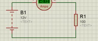
- Each wire in the cable is tested against the other wires that are connected together. The wire under test is connected to the “L” socket, the remaining wires connected together to the “Z” socket. A similar connection diagram is shown in the figure.
Connecting a megohmmeter
If the indicators meet the standard, then testing can be completed, otherwise testing continues.
- Each of the wires is tested relative to ground.
- Each wire is checked in relation to other wires.
Test algorithm
Having considered all the main stages, you can proceed directly to the order of actions:
- Preparatory stage (fully described above).
- Installation of portable grounding to remove electrical charge.
- The voltage level is set on the megohmmeter; for household wiring - 1000.0 volts.
- Depending on the expected result, the resistance measurement range is selected.
- Checking the de-energization of the tested object, this can be done using a voltage indicator or a multimeter.
- Special crocodile probes of the measuring wires are connected to the line.
- Disconnecting portable grounding from the tested object.
- High voltage is supplied. In electronic megohmmeters, to do this, just press the “Test” button; if you are using an analog device, you should rotate the dynamo handle at a given speed.
- We read the device readings. If necessary, the data is entered into the measurement protocol.
- We remove residual voltage using portable grounding.
- We disconnect the measuring probes.
To measure the condition of other current-carrying conductors, the procedure described above is repeated until all elements of the object are checked, that is, we are talking about the end of measurements when testing electrical equipment.
Based on the test results, a decision is made on the possibility of operating the electrical installation.
Safety when working with a megohmmeter
Since the megohmmeter supplies high voltage, it is a potential source of danger both for those who supply this voltage and for those who are near the equipment or cable to which this voltage is supplied.
What do you need to remember when working with a megohmmeter? Firstly, it is necessary to correctly connect the ends to the device, and secondly, it is necessary to securely fasten the ends through which voltage is supplied to the electrical equipment. Also, do not forget about grounding the equipment under test, both before and after the measurement, to remove any residual charge.
Standards
As a result of the measurements, the actual value of the wire insulation resistance is obtained. It must be compared with standard data. To understand which document needs to be used in a particular case, you need to know what standards exist. It should be taken into account that the limit values provided by them may vary significantly. There are insulation resistance standards for:
- Power or signal cables used in various environments.
- Power electrical installations intended for industrial use.
- Household appliances equipped with a power cord.
Checking the electrical insulation resistance depends on the voltage present in the electrical network. In this case, it is necessary to take into account what model of equipment is used. Before checking, you should read the relevant documents, which indicate the standards for the insulation resistance of a wire or cable. The following is a list of the most common situations for which the permissible insulation resistance is specified:
- When using electric stoves, the insulation resistance is at least 1 MOhm.
- If the cable is laid in an area where climatic conditions can be considered normal, the minimum insulation resistance is 0.5 MOhm.
- For insulation of electrical equipment consuming voltages up to 1000 V, the maximum resistance is 1 MOhm.
- If the supply voltage of the electrical device is in the range of 100–380 V, then the limitation is 0.5 MOhm.
- In cases where the supply voltage does not exceed 50 V, the insulation resistance must be at least 0.3 MOhm.
- For cables and wires used in switchboard installations, the insulation resistance standard is 1 MOhm.
Tricks with a megaohmmeter
About tricks with a megaohmmeter, I can only note that we have one employee whom we tested at 500 volts, here, as he says, the main thing is to keep the ends tight and not let go. Attention!!! I don’t advise you to repeat this!!! . It was a terrible sight, of course. But theoretically, the current is small and the thermal effect is not annoying.
In general, I wish you good luck in your work with a megohmmeter, and be careful, because our profession is not only very interesting, but also quite dangerous. TB above all!!!
Read more about measuring Rx cable with a megohmmeter
You can also familiarize yourself with a multimeter
How is the check carried out?
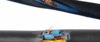
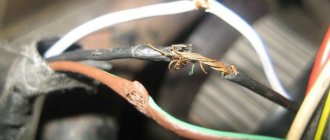
Insulation resistance measurements are in most cases carried out for the purpose of checking connecting wires and cables. If they are exposed to various influences, it is especially important to be confident that the insulation resistance meets safety requirements.
The measurement is carried out based on Ohm's law. In this case, a certain voltage is applied to the insulation, and then the current flowing through it is measured. To calculate the resistance, the formula of Ohm's law is used: Riz = U/I.
Insulation resistance measurements are performed not only to monitor the safety of the electrical network, but also during regular maintenance. Measurements of the insulation resistance of electrical wiring elements are necessary in cases where the insulation remains intact. If it is missing or there are wire cuts or other damage in certain places, then there is no point in taking measurements at this moment. First you need to repair the wire or replace it with a working one.