Periodic alternating current
One that, while changing, manages to return to its original value at equal time intervals and at the same time goes through the entire cycle of its transformations, is called periodic. It can be traced on a sinusoid displayed on the oscilloscope screen.
Period and amplitude of sinusoidal oscillation
It can be seen that at regular intervals the graph repeats without changes. These intervals are designated by the letter T and are called periods. The frequency with which a certain number of similar periods fits into a unit of time is the frequency of an alternating current.
It can be calculated using the AC frequency formula:
f = 1/T,
Where:
- f – frequency, Hz;
- T – period, s.
Frequency is equal to the number of cycles per second and has a unit of 1 hertz (Hz).
Attention! The SI unit of frequency is named after Heinrich Hertz. 1 hertz (Hz, Hz) = 1 s-1
Multiple and submultiple units, expressed by standard SI prefixes, are applicable to it.
Frequency standards
In order to ensure coordination of the operation of sources of alternating electricity, transmission systems, reception and operation of electrical consumers, frequency standards are applied. Frequency used in electrical engineering in some countries:
- 50 Hz – countries of the former USSR, the Baltic states, European countries, Australia, North Korea and others;
- 60 Hz is the standard adopted in the USA, Canada, the Dominican Republic, Taiwan, the Cayman Islands, Cuba, Costa Rica, South Korea and some other countries.
In Japan, both frequencies are used. Eastern regions (Tokyo, Sendai, Kawasaki) use 50 Hz. Western regions (Kyoto, Hiroshima, Nagoya, Okinawa) use a frequency of 60 Hz.
For your information. The railway infrastructure of Austria, Norway, Germany, Switzerland and Sweden still uses the 16.6 Hz frequency.
Electrification of railways using alternating current[edit]
The Russian AC passenger electric locomotive EP1P is produced at the Novocherkassk Electric Locomotive Plant.
In Russia and the republics of the former USSR, about half of all railways are electrified using single-phase alternating current with a frequency of 50 Hz. Voltage ~ 25 kV (usually up to 27.5 kV, taking into account losses)
is fed to the contact wire, the second (return) wire is the rails.
Electrification is also carried out according to the 2 × 25 kV (two twenty-five kilovolts each)
, when a voltage of ~ 50 kV is applied to a separate supply wire
(usually up to 55 kV, taking into account losses)
, and half the voltage of 50 kV is applied to the contact wire from autotransformers
(i.e. 25 kV)
. Electric locomotives and AC electric trains do not require alteration when operating on 2 × 25 kV sections.
A policy is being pursued to further expand the AC traction range both through newly electrified sections and through the transfer of some lines from direct current to alternating current. Transferred to 1990s - 2000s:
- on the East Siberian Railway: section Slyudyanka - Irkutsk - Zima; - on the Oktyabrskaya Railway: section Loukhi - Murmansk; — on the Volga Railway: Saratov and Volgograd railway junctions; - on the North Caucasus Railway: sections Mineralnye Vody - Kislovodsk and Beshtau - Zheleznovodsk.
It should be noted that dual-system electric locomotives are also produced that can operate on both alternating and direct current (see VL61D, VL82 and VL82M, EP10, EP20).
Is it possible to represent the effective (effective) values of e. by vectors? d.s. and currents?
This important question usually causes confusion. You can answer it as follows.
If you need to determine the instantaneous values of a sinusoidal quantity, then it is more convenient to take the vector representing its maximum value, because it is its projection onto the axis that gives the instantaneous values. But in practical activities, they usually deal not with instantaneous values, but with 2 effective values, for example, they say 220 V, meaning by this the effective value and without thinking about the maximum values, which are 41% greater, or about other instantaneous values. Therefore, vector diagrams are usually constructed for effective values. In this case, the phase shift angles between the current, e. d.s., voltage and the like are visible quite clearly, and the results of addition and subtraction of vectors are directly obtained in effective values, which is convenient.
Voltage or potential difference?
It should be noted that voltage and potential difference are one and the same thing. Essentially, it is a force that can cause electrical charges to move in a stream. It doesn't matter where this movement is directed.
Potential difference is simply another expression for voltage. It is clearer and perhaps clearer, but it does not change the essence of the matter. Therefore, the main question is where the voltage comes from and what it depends on.
As far as the 220 Volt home network is concerned, the answer is simple. At a hydroelectric power station, the flow of water rotates the generator rotor. The rotational energy is transformed into tension. A nuclear power plant first turns water into steam. He turns the turbine. In a gasoline power plant, the rotor is rotated by the force of burning gasoline. There are other sources, but the essence is always the same: energy turns into tension.
It's time to ask the question about the dependence of voltage on frequency. But we don't yet know where the frequency comes from.
Instantaneous power in an alternating current circuit with active resistance.
With variable voltage and current values, the rate of conversion of electrical energy in the receiver, i.e. its power, also changes. Instantaneous power is equal to the product of instantaneous voltage and current values: p = Umsinωt * Imsinωt = UmImsin2ωt
From trigonometry we find
A more clear idea of the nature of the change in power in a circuit is given by a graph in a rectangular coordinate system, which is constructed after multiplying the ordinates of the voltage and current curves corresponding to a number of values of their common argument - time t. The dependence of power on time is a periodic curve (Fig. 13.2). If the time axis t is raised according to the drawing by the amount p = Pm√2 = UmIm√2, then relative to the new axis t' the power graph is a sinusoid with double frequency and an initial phase of 90°:
Thus, in the original coordinate system, the instantaneous power is equal to the sum of the constant value Р = UmIm√2 and the variable р':
p = P + p'
Analyzing the instantaneous power graph, it is easy to notice that the power remains positive during the period, although the current and voltage change their sign. This is achieved due to the phase coincidence of voltage and current.
The constancy of the power sign indicates that the direction of the flow of electrical energy remains unchanged during the period, in this case from the network (from the energy source) to the receiver with resistance R, where the electrical energy is irreversibly converted into another type of energy. In this case, electrical energy is called active.
If R is the resistance of the conductor, then, in accordance with the Lenz-Joule law, electrical energy in it is converted into heat.
Standardized requirements for indicators
In the Russian Federation, requirements for the quality of power system operation are standardized.
In accordance with GOST 13109-97, the frequency in the power system must be continuously maintained at the level f = 50 ± 0.2 Hz, while a short-term frequency deviation up to ∆f = 0.4 Hz is allowed.
Analyzing the dependence of current on frequency, we can conclude that if the connected load is purely active in nature (for example, a resistor), then over a wide range the current will not have a dependence on frequency. In the case of sufficiently high frequencies, when the inductance and capacitance of the connected load are characterized by a resistance comparable to the active one, the current strength will have a certain dependence on frequency.
In other words, when the frequency of the current varies, a change in capacitance occurs, a change in which, in turn, leads to a change in the current flowing through the circuit.
That is, as the frequency increases, the capacitance decreases and the current flowing through the circuit increases.
The mathematical expression of the dependence will have the following form: I = UCω;
The dependence, taking into account active resistance, will be determined by the following expression: I (ω) = UCω √(R2 • C2 • ω2 + 1).
High frequency currents
HDTV – this is their abbreviation; they are used for melting metals and hardening the surface of metal products. HDTV are currents with a frequency of more than 10 kHz. Induction furnaces use HDTV by placing a conductor inside a winding through which the HDTV is passed. Under their influence, eddy currents arising in the conductor heat it up. By adjusting the strength of the HDTV, the temperature and heating rate are controlled.
Interesting. The metal to be melted can be suspended in a vacuum using a magnetic field. It does not require a crucible (a special ladle for heating). This is how very pure substances are obtained.
Advantages of using HDTV in different cases:
- rapid heating during forging and rolling of metal;
- optimal temperature conditions for soldering or welding parts;
- melt even very refractory alloys;
- cooking in microwave ovens;
- Darsonvalization in medicine.
HDTV is obtained using installations that include an oscillating circuit or electric machine generators. The stator and rotor of the generators have teeth on the sides facing each other. Their mutual movement generates a pulsation of the magnetic field. The greater the product of the number of rotor teeth and its rotation frequency, the greater the output frequency.
Effective value of alternating sinusoidal current[edit]
If all the positive and negative instantaneous values of the alternating sinusoidal current are added, then their sum will be equal to zero.
But if the algebraic sum of all instantaneous values for a period is equal to zero, then the average value of this current for a period is also equal to zero: . The average value of the sinusoidal current over a period cannot be used to measure this current.
To judge the magnitude of the alternating sinusoidal current, alternating current is compared with direct current by their thermal effect.
Two currents, one of which is sinusoidal and the other constant, are equivalent in thermal effect if they, flowing through the same resistances, emit the same amount of heat over the same periods of time. The effective value of an alternating sinusoidal current is numerically equal to a direct current, equivalent to a given sinusoidal current, that is, separately releasing the same amount of heat in the same resistance over the same period of time.
It was found experimentally, and then confirmed theoretically, that the magnitude of the effective value of the alternating sinusoidal current is in a strictly defined dependence on the amplitude of this current: that is, the effective value of the alternating sinusoidal current is several times less than the amplitude of this current.
The ammeter of an electromagnetic or electrodynamic system, connected to an alternating sinusoidal current circuit, shows the effective value of the current.
Similar to the effective value of an alternating sinusoidal current, we can talk about the effective value of an alternating sinusoidal electromotive force or an alternating sinusoidal voltage.
The effective value of the voltage is less than its amplitude:
or.
A voltmeter of an electromagnetic or electrodynamic system connected to an alternating sinusoidal current network shows the effective value of the sinusoidal voltage.
For example, in an electrical outlet the electrical voltage
is RMS value , the peak voltage will be Volts.
These formulas are valid only for sinusoidal current; if the pulses are triangular, sawtooth, rectangular or other in shape, a different calculation method is required.
Using the method of mathematical analysis, it is possible to determine the average value of an alternating sinusoidal current over half a period, for example, over a positive half-wave of a sinusoid.
The average value of alternating sinusoidal current for half a period is
.
You can also determine the ratio of the effective current value to the average value for half a period (positive half-wave). This ratio for a sinusoidal current is:
.
Generating alternating current[edit]
The simplest alternating current generator: if a flywheel with several pairs of permanent magnets installed in it is rotated around a wire coil wound on a magnetic core made of transformer steel, then a sinusoidal EMF will be induced in the coil (conventionally shown as one turn), and when a load is connected, an alternating current will appear in the electrical circuit current. Used on vehicles (mopeds, light motorcycles, snowmobiles, jet skis, as well as outboard boat motors), works in conjunction with a rectifier and voltage regulator (see Magdino)
.
Main article: Alternator
The operating principle of an alternating current generator is based on the law of electromagnetic induction - the induction of an electromotive force in a rectangular loop (wire frame) located in a uniform rotating magnetic field.
The electromotive force of an alternator is determined by the formula:
, Where
— number of turns;
- magnetic induction of the magnetic field in volt-seconds per square meter ( T
,
Tesla
);
— the length of each of the active sides of the circuit in meters;
— angular velocity of the sinusoidal electromotive force, in this case equal to the angular velocity of rotation of the magnet in the circuit;
— phase of the sinusoidal electromotive force.
The frequency of the alternating current generated by the generator is determined by the formula:
, Where
— frequency in hertz;
— number of rotor revolutions per minute;
— number of pairs of poles.
According to the number of phases, alternating current generators are:
- three-phase generators are the main type of powerful industrial generators; See also three-phase power supply system, three-phase motor, three-phase alternating current automobile generator
. - single-phase generators, used, as a rule, in low-power gasoline power plants, built into internal combustion engines of mopeds, light motorcycles, snowmobiles, jet skis, and outboard boat engines; See also capacitor motor, single-phase motor
. - two-phase generators are much less common compared to single-phase and three-phase. See also two-phase electrical network, two-phase motor
.
Modified sine wave generated by an inverter.
Invertersedit
Direct current can be converted to alternating current using an inverter.
It should be noted that inexpensive inverter models have a non-sinusoidal alternating current output, usually rectangular pulses or a modified sine wave. To produce a sinusoidal current, the inverter must have a master oscillator (usually a specialized microcircuit that generates a sinusoidal electrical signal, which then controls the operation of thyristor or transistor electronic switches.
Phase splitteredit
Three-phase current can be obtained from single-phase current using a phase splitter. These electric machines are used, in particular, on electric locomotives such as VL60, VL80.
How to calculate Xc
The current strength of a circuit with constant voltage readings at the time of operation of the electric capacitor is equal to 0. Its value in a circuit with alternating voltage after connecting the capacitor I? 0. As a result, the capacitor imparts less Xc to a chain with a variable voltage than to a chain with a constant voltage.
Formula for calculating voltage in one second
Formula for calculating the amount of electric current in an instant
It turns out that voltage changes differ in phase from current changes by π/2.
According to the law formulated by Ohm, the strength of the electric current is directly proportional to the magnitude of the circuit voltage. Formula for calculating the largest values of voltage and current:
The largest values of voltage and current can be calculated using the formula: The final formula for calculating capacitance in an alternating current circuit
ω = 2πf.
f is an indicator of the frequency of intermittent current, measured in hertz;
ω is an indicator of the angular frequency of the current;
C is the size of the capacitor in farads.
Important! Xc is not a parameter of the conductor; it depends on such characteristics of the electrical circuit as the frequency of the electric current. Increasing the values of this value causes an increase in the transmittance of the capacitor (the limit of its resistance to intermittent current decreases)
Increasing the values of this value causes an increase in the transmitting capacity of the capacitor (the limit of its resistance to intermittent current decreases).
Let's imagine that a capacitor with a capacity of 1 μF is connected to the circuit. It is necessary to calculate the level of capacitance at a frequency of 50 Hz and how the capacitance of the AC circuit changes at a frequency of 1 kHz. The voltage amplitude applied to the capacitor is 50 V.
After entering the data into the formula that determines Xc, the following values are obtained:
Result for frequency 50 Hz Result for 1 kHz
Capacitive reactance is equated to the ratio of deviations in voltage fluctuations of the terminals of an electrical chain with capacitive parameters (with small inductive and active resistances) to fluctuations in the electric current of the chain. It is equivalent to an electric capacitor.
Alternating current. Production, transmission and consumption of electrical energy
An alternating current is a current that changes in magnitude and direction according to a harmonic law.
Alternating current is an example of forced electromagnetic oscillations. To describe alternating electric current, the following quantities are used:
• instantaneous current value – i;
• instantaneous voltage value – u;
• amplitude value of current – Im;
• amplitude voltage value – Um.
The alternating current circuit is an oscillatory circuit to which an external sinusoidal emf is applied. Various loads can be included in an alternating current circuit: a resistor, a coil, a capacitor.
Active resistance
A conductor that converts all the energy of an electric current into internal energy is called active resistance \( R \). (We used to call this quantity resistance.) Active resistance depends on the material of the conductor, its length and cross-sectional area and does not depend on the frequency of the alternating current.
In a conductor with active resistance, the oscillations of current and voltage are in phase:
Instantaneous power value: \( p=i^2R, \)
average power value for the period: \( \overline{p}=\frac{I_m^2R}{2}. \)
The effective value of the alternating current \(I_D \) is the value of the direct current strength, which in the same conductor releases the same amount of heat as alternating current in the same time:
The effective value of the alternating current voltage \(U_D\) is the value of the direct current voltage, which in the same conductor releases the same amount of heat as alternating current in the same time:
For a circuit with active resistance, Ohm's law is satisfied for instantaneous, amplitude and effective values.
Inductive reactance
The coil in an AC circuit has a higher resistance than in a DC circuit. In such a circuit, voltage fluctuations are ahead of current fluctuations in phase by \(\pi/2\). Fluctuations in current and voltage occur according to the law:
Amplitude of current in the coil:
where \( L \) is the inductance of the coil.
Inductive reactance \( X_L \) is a physical quantity equal to the product of the cyclic frequency and the inductance of the coil:
Inductive reactance is directly proportional to frequency. The physical meaning of inductive reactance: the self-inductive emf prevents the current from changing in it. This leads to the existence of inductive reactance, which reduces the current strength.
For a circuit with inductive reactance, Ohm's law is satisfied.
Current power through the coil
Let alternating voltage be applied to the coil. The current through the coil lags in phase from the voltage by:
For instantaneous power we get:
Again the average power is zero. The reasons for this are, in general, the same as in the case of a capacitor. Let's look at the graphs of voltage and current through the coil over a period (Fig. 5).
Rice. 5. Voltage on the coil and current through it
We see that during the second and fourth quarters of the period, energy enters the coil from the external circuit. In fact, voltage and current have the same signs, the current increases in magnitude; To create a current, the external electric field does work against the vortex electric field, and this work goes to increase the energy of the magnetic field of the coil.
In the first and third quarters of the period, the voltage and current have different signs: the coil returns energy to the circuit. The vortex electric field, which maintains a decreasing current, moves charges against the external electric field and thereby does positive work. How is this work accomplished? Due to the energy previously accumulated in the coil.
Thus, the energy stored in the coil during one quarter of the period is completely returned to the circuit during the next quarter. Therefore, the average power consumed by the coil is zero.
Harmonic electromagnetic oscillations
Harmonic electromagnetic oscillations are periodic changes in charge, current and voltage that occur according to a harmonic - sinusoidal or cosine - law.
In electrical circuits this can be oscillations:
- current strength – \( i=I_m\cos(\omega t+\varphi+\frac{\pi}{2}); \)
- voltage – \( u=U_m\cos(\omega t+\varphi); \)
- charge – \( q=q_m\cos(\omega t+\varphi); \)
- EMF – \( \varepsilon=\varepsilon_m\sin\omega t. \)
In these equations, \( \omega \) is the cyclic frequency, \( \varphi \) is the initial phase of oscillations, amplitude values: current strength - \( I_m \), voltage - \( U_m \) and charge – \( q_m \).
Important! If at the initial moment of time the charge has a maximum value and the current strength is zero, then the charge oscillates according to the cosine law with an initial phase equal to zero. If at the initial moment of time the charge is zero and the current is maximum, then the charge oscillates according to the sine law.
The current strength is equal to the first derivative of charge versus time:
The amplitude of current fluctuations is equal to:
Oscillations of charge and voltage in the oscillatory circuit occur in the same phases. The voltage amplitude is:
The current oscillations are shifted in phase relative to the charge oscillations by \( \pi/2 \).
Period of free electromagnetic oscillations
The period of free electromagnetic oscillations is found according to Thomson's formula :
where \( L \) is the inductance of the coil, \( C \) is the electrical capacity of the capacitor.
Cyclic frequency: \( \omega=\frac{2\pi}{T}=\frac{1}{\sqrt{LC}} \)
Important! The period and cyclic frequency do not depend on the initial conditions, but are determined only by the inductance of the coil and the electrical capacitance of the capacitor. The amplitude of charge and current fluctuations is determined by the initial energy reserve in the circuit.
With free harmonic oscillations, periodic energy transformation occurs. The period of energy oscillations is two times less than the period of oscillations of charge, current and voltage. The frequency of energy oscillations is twice the frequency of oscillations of charge, current and voltage.
General concept of alternating current[edit]
Since alternating current in the general case changes in an electrical circuit not only in magnitude, but also in direction, one of the directions of alternating current in the circuit is considered conditionally positive, and the other, opposite to the first, conditionally negative. In accordance with this, the magnitude of the instantaneous value of the alternating current is considered positive in the first case, and negative in the second case.
Alternating current is an algebraic quantity, its sign is determined by the direction in which the current flows in the circuit at the given moment in time - positive or negative.
The amount of alternating current corresponding to a given moment in time is called the instantaneous value of alternating current
.
The maximum instantaneous value of the alternating current that it reaches during its change is called the current amplitude
.
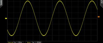
A graph of alternating current versus time is called an alternating current diagram.
Expanded diagram of alternating sinusoidal current
The figure shows an expanded diagram of alternating current
, changing over time in magnitude and direction. On the horizontal axis, time intervals are plotted on a certain scale, and on the vertical axis, current values are plotted upward - from the starting point - positive, down - negative. The part of the expanded current diagram located above the time axis characterizes the change in positive values over time, and the part located below the time axis characterizes the change in negative values.
At the initial moment of time, the current is zero. Then it grows over time in a positive direction, at the moment of time it reaches its maximum value, after which it decreases in value and at the moment of time it becomes equal to zero. Then, having passed through the zero value, the current changes its sign to the opposite, that is, it becomes negative, then increases in absolute value, then reaches a maximum at , after which it decreases and becomes equal to zero.
Free electromagnetic oscillations. Oscillatory circuit
Electromagnetic oscillations are periodic changes in charge, current and voltage that occur in an electrical circuit. The simplest system for observing electromagnetic oscillations is an oscillatory circuit.
An oscillatory circuit is a closed circuit formed by a capacitor and a coil connected in series.
The coil resistance \( R \) is zero.
If you charge the capacitor to the voltage \( U_m \), then at the initial moment of time \( t_1=0 \), the voltage on the capacitor will be equal to \( U_m \). The charge of the capacitor at this moment in time will be equal to \( q_m=CU_m \). The current strength is zero.
The total energy of the system will be equal to the energy of the electric field:
The capacitor begins to discharge, and current begins to flow through the coil. Due to self-induction in the coil, the capacitor discharges gradually.
The current reaches its maximum value \( I_m \) at time \( t_2=T/4 \). The charge on the capacitor at this moment is zero, the voltage on the capacitor is zero.
The total energy of the system at this moment in time is equal to the energy of the magnetic field:
At the next moment of time, the current flows in the same direction, gradually (due to the phenomenon of self-induction) decreasing to zero. The capacitor is recharged. The charges of the plates have charges opposite in sign to the original ones.
At the moment of time \( t_3=T/2 \) the charge of the capacitor is \( q_m \), the voltage is \( U_m \), the current strength is zero.
The total energy of the system is equal to the energy of the electric field of the capacitor.
The capacitor then discharges again, but the current through the coil flows in the opposite direction.
At the moment of time \( t_4=3T/4 \) the current strength in the coil reaches its maximum value, the voltage on the capacitor and its charge are equal to zero. From this moment, the current in the coil begins to decrease, but not immediately (the phenomenon of self-induction). The energy of the magnetic field is converted into the energy of the electric field. The capacitor begins to charge, and after some time its charge is equal to the original one, and the current strength becomes equal to zero.
After a time equal to the period \( T \), the system returns to its initial state. One complete oscillation has occurred, then the process is repeated.
Important! The oscillations occurring in the oscillatory circuit are free. They are accomplished without any external influence - only due to the energy stored in the circuit.
In the circuit, the energy of the electric field of the capacitor is converted into the energy of the magnetic field of the coil and vice versa. At any arbitrary moment in time, the total energy in the circuit is equal to:
where \( i, u, q \) – instantaneous values of current, voltage, charge at any time.
These oscillations are damped. The amplitude of oscillations gradually decreases due to the electrical resistance of the conductors.
Using the formula
Using Ohm's law allows you to construct the time characteristics of various elements. Using it, it is easy to calculate the loads for electrical circuits, select the desired cross-section of wires, and select the correct circuit breakers and fuses. Understanding the law makes it possible to use the correct power source.
The use of Ohm's Law can be applied in practice to solve a problem. For example, let there be an electrical line consisting of series-connected elements, such as capacitance, inductance and resistor. In this case, the capacitance C = 2*F, the inductance L = 10 mH, and the resistance R = 10 kOhm. It is required to calculate the impedance of the complete circuit and calculate the current. In this case, the power supply operates at a frequency equal to f = 200 Hz and produces a signal with an amplitude U = 12 0 V. The internal resistance of the power supply is r = 1 kOhm.
First you need to calculate the reactance in the AC circuit. So, the capacitive reactance is found from the expression: Xc = 1/ (2 *p *F*C) and at a frequency of 200 Hz it is equal to: Xc = 588 Ohm.
The inductive reactance is found from the expression: XL = 2*p*F* L. At f = 200 Hz and it leaves: X*L = 1.25 Ohm. The total resistance of the RLC circuit will be: Z = ((10 *10 3 +1*10 3 ) 2 + (588−1.25) 2 ) ½ = 11 kOhm.
The potential difference, changing according to the harmonic sine law, will be determined: U (t) = U * sin (2* p *f*t) = 120*sin (3.14*t). The current will be equal to: I (t) = 10* 10 −3 + sin (3.14*t+p/2).
Using the calculated data, it is possible to construct a current graph corresponding to a frequency of 100 Hz. To do this, the dependence of the current on time is displayed in a Cartesian coordinate system.
It should be noted that Ohm's law for an alternating signal differs from that used for classical calculations only by taking into account the impedance and frequency of the signal
And it is important to take them into account, since any radio component has both active and reactance, which ultimately affects the operation of the entire circuit, especially at high frequencies. Therefore, when designing electronic structures, in particular pulsed devices, it is Ohm’s complete law that is used for calculations
Alternating current
The term explains the characteristics of one of the types of electric current, which constantly changes over time. Changes occur both in absolute values and in direction. As a special case, changes are possible only in magnitude, while maintaining the direction of the oscillatory motion in the electrical circuit unchanged. This current (alternating) is widely used in the lighting network of households, residential buildings, as well as at numerous industrial facilities.
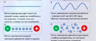
If with direct current the electrons always move in one direction, then alternating current is characterized by multiple changes not only in direction, but also in values (several times per unit time). All such changes occur in accordance with one law - harmonic. In a picture displayed using an oscilloscope, such a picture can be seen in the form of a clear, geometrically accurate sinusoid
It is important to understand that alternating current is an algebraic quantity, therefore its sign can only be indicated taking into account a specific instantaneous value (taking into account the direction in which the electrons are moving at a particular moment in time)
Relationship between frequency and operation of electrical equipment
Circuits and electrical equipment are designed to operate at either fixed or variable frequency.
Rotation speed: formula
For electrical equipment that operates normally at a fixed frequency, changing this indicator will cause operational disturbances. For example, a 50 Hz motor will run slower if the frequency is below 50 Hz and faster if the frequency is above 50 Hz.
Important! There is a proportional relationship between the frequency and speed of the electric motor. A one percent frequency deviation will result in the same change in motor speed.
The frequency indicator is one of the main parameters by which the quality of electricity in power systems is assessed. In addition, it shows the correspondence between generated and consumed power. The permissible value of frequency fluctuations in the energy system is allowed no higher than 0.2 Hz. Moreover, when approaching the extreme indicator, the energy sector takes immediate measures to return it to the fluctuation range of ±0.05 Hz. Although the minimum limits are regulated at 0.4 Hz. If the frequency decreases more significantly, an avalanche-like drop may occur due to a disruption in the operation of the power plant’s own needs and subsequently a collapse of the power system.
Automatic frequency shedding
In order to prevent these processes, AFR (automatic frequency unloading) is installed. When the consumption power exceeds the generated power and there is no reserve of active power, the AFC at electrical substations automatically disconnects consumers in accordance with established queues. When the frequency is restored, it automatically turns on in the reverse order. The activation settings of the AFC stages are regulated by frequency value and time delay in seconds.
Important! According to the Technical Operation Rules, automatic frequency unloading should not allow the frequency to decrease below 45 Hz even for a minimum time.
Pulsation period and frequency
The physical essence of alternating current is the movement of electrons in a conductor, first in one direction, then in the other direction. A full cycle of movements back and forth is completed over a certain period, determined by the frequency of oscillations: T = 1/ f.
Cycle intensity
For the conditions of Russian power grids, the indicator f = 50 Hz, and the time of one pulsation is T = 1/50 = 0.02 seconds. Feedback of two parameters allows you to determine the frequency ~ of the current from the duration of the signal: f = 1/0.02 = 50 Hz.
One hertz means 1 oscillation per second. The faster the electromotive force changes, the faster the radius vector reverses and the period shortens. Accordingly, when speed is increased, the frequency increases: the values of T and f are inversely proportional, the larger one is, the smaller the second. The values of the characteristic f vary widely, which predetermines the use of expanded terminology:
| Number of zeros after one | Prefix to the hertz dimension |
| 3 (thousand) | Kilo (kHz) |
| 6 (million) | Mega (MHz) |
| 9 (billion) | Giga (GHz) |
Depending on the magnitude, the frequency of alternating current is divided into the following subgroups:
- industrial: 16–25 Hz on railway networks in some countries, 25 and 75 Hz in interlocking circuits of track circuits, in autonomous systems of aviation and military energy - 400 Hz, in some industrial and agricultural installations 200–400 Hz;
- sound are in the range 20–20000 Hz (20 kHz), in transmitting antennas - up to 1.5 GHz;
- technical: automation - the range from 1 kHz to 1 GHz is used, metallurgy and mechanical engineering: smelting, welding and heat treatment of metals;
- satellite communication radar stations, special systems GLONASS, GPS - up to 40 GHz and higher.
High-frequency currents (HFC) begin at a level of tens of kHz, when the radiation of electromagnetic waves and the skin effect are significantly manifested: the charge moving in the conductor is distributed not over the cross-section, but in the surface layer.
The danger of multi-frequency charges
The equivalent voltages of alternating and direct current in terms of their impact on the human body are 42 V and 120 V, respectively. The inequality of danger disappears when the EMF reaches 500 V, and at higher values the constant one becomes more dangerous. Manifestations of the adverse effects of the latter are thermal and electrolytic, and variable ones are mainly expressed in the contraction of blood vessels, muscles, and vocal cords. In this case, the frequency of the current has a decisive influence on the danger:
- 40–60 Hz - the greatest threat of damage, the possibility of heart fibrillation; a further increase in the intensity of charge oscillations leads to a reduction in risk, but the probability of death remains within the entire range of industrial frequencies - up to 500 Hz;
- above 10 kHz, HDTV begins - they are safe up to the level of 1 MHz relative to internal lesions, which is due to the skin effect, but they cause burns and the threat from them is no less than from constant or variable ones of the previous group;
- High frequency currents are accompanied by electromagnetic radiation - from this side there is the possibility of a negative impact on living organisms.
Action of alternating electric field
An alternating electric field causes longitudinal vibrations of free charges in a conductor and rotational vibrations of molecules in a dielectric. These processes are accompanied by the release of heat.
a conductor in an alternating electric field
(eg electrolyte). The high-frequency field causes oscillatory movement of ions, i.e. conduction current, accompanied by a thermal effect.
The amount of heat can be expressed through tension E
electric field in a conducting body, the resistance of which is assumed to be equal. To do this, we perform the following transformations:
Dividing this equality by the volume of the body (S L), we obtain that the amount of heat released in 1 s in 1 m3 of tissue is proportional to the square of the amplitude of the electric field intensity Em
and inversely proportional to the electrical resistivity
p
:
Let in an alternating electric field with amplitude E
there is
a dielectric
with a relative dielectric constant e. Under the influence of an alternating electric field, orientational and structural polarization of molecules occurs. In this case, vibrational motion of the molecules occurs, accompanied by the release of heat (dielectric losses). The amount of heat released depends on the circular frequency of the field ω and the angle δ by which the oscillations of the molecules lag behind the oscillations of the field strength in phase (angle 5 is called the dielectric loss angle):
Action of alternating magnetic field
Let there be a conductor in an alternating magnetic field .
As a result of the phenomenon of electromagnetic induction, eddy currents (Foucault currents) appear in it, heating the object. The amount of heat released in 1 s per 1 m3 of a substance is determined by the ratio:
where B is the amplitude value of magnetic induction; ω—circular frequency; R
— electrical resistivity of the fabric;
k
is a certain coefficient that takes into account the geometry of the body.
Use of currents and fields for therapeutic purposes
Biological tissues and organs are heterogeneous formations: some of them are dielectrics, others are conductors. A significant part of the body consists of biological fluids (electrolytes), containing a large number of ions.
D.C
Under the influence of a constant electric field, ions contained in biological tissues come into directed motion. In this case, they are separated and their concentration changes in various tissue elements.
Electrophoresis —
a method based on the introduction of a substance through the skin or mucous membranes under the influence of direct current. Pads moistened with the appropriate medication are placed on the skin under the electrodes. Anions (iodine, heparin, bromine) are introduced through the cathode, and cations (Na, Ca, novocaine) are introduced through the anode.
Galvanization -
a physiotherapeutic method based on passing a direct current of 60-80 V through the body tissues.
High frequency currents
The primary effect of alternating (harmonic) current and electromagnetic field on biological objects is as follows: a) displacement of ions in electrolyte solutions, their separation, redistribution; b) change in the polarization of dielectrics.
High frequency currents.
At frequencies above approximately 500 kHz, the displacement of ions becomes commensurate with their displacement as a result of molecular thermal motion, so the current or electromagnetic wave will not cause irritation.
The main primary effect in this case is thermal effect.
(Direct current and low frequency currents are not suitable for heating tissues, since their use at high values can lead to electrolysis and destruction).
Advantages
therapeutic warming with HF electromagnetic vibrations before a heating pad:
• formation of heat in the internal parts of the body;
• by selecting the appropriate frequency, it is possible to carry out thermoselective effects;
• you can dose the heating by adjusting the generator power;
• the occurrence of intramolecular processes that lead to specific effects.
Let's calculate the amount of heat q,
released per unit volume.
The current power spent on heating tissue is determined by the formula P = I 2 ·R.
Let us transform it, assuming that a sample of biological tissue of length
L
has a resistivity p and is in contact with two flat electrodes of area S (Fig. 12.3).
Let the current density j be the same at all points of the tissue and equal to the current density at the electrodes. Considering this, we obtain:
Rice. 12.3. Diagram of the location of biological tissue between the electrodes
where V = SL
- volume of fabric.
Dividing the resulting expression by volume, we find out the amount of heat q
released in 1 s in 1 m3:
Passing high frequency current through tissue is used in the following physiotherapeutic procedures.
Diathermy
(through heating) - obtaining a thermal effect in deep-lying tissues. In diathermy, a current with a frequency of 1-2 MHz, a voltage of 100-150 V, and a current strength of 1-1.5 A is used. In this case, the skin, fat, bones, and muscles become very hot (since they have the highest resistivity). Organs rich in blood or lymph heat up less: lungs, liver, lymph nodes.
The disadvantage of diathermy is the unproductive release of heat in the skin layer and subcutaneous tissue.
Local darsonvalization.
In this case, a current with a frequency of 100-400 kHz, a current strength of
I
= 10-15 mA and a voltage of tens of kV is used.
High frequency currents are used for surgical purposes.
Diathermocoagulation -
cauterization, “welding” of tissue. In this case, a current density of 6-10 mA/mm2 is applied, as a result of which the tissue temperature rises and the tissue coagulates.
Diathermotomy
- tissue dissection using a blade-shaped electrode. In this case, the current density is 40 mA/mm2.
Electrosurgical treatment is accompanied by less blood loss.
Alternating magnetic field
If you place biological tissue in an alternating magnetic field (for example, near the end of an alternating current coil), then as a result of the phenomenon of electromagnetic induction, eddy currents (Foucault currents) are formed in the conducting tissues, heating the object.
Heating an area of the body under the influence of a high-frequency magnetic field (frequency 10-15 MHz) is called inductothermy.
The impact diagram is shown in Fig. 12.4.
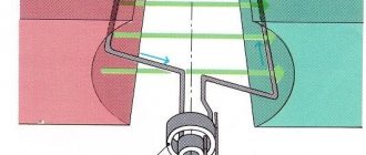
With inductothermy, tissues with low resistivity heat up more. Tissues rich in blood vessels, such as muscles, will heat up more strongly. Tissues such as fat will heat up less. Inductothermy in a UHF magnetic field is also used.
Rice. 12.4. Scheme of influence during inductothermy
A sample is placed into a hollow coil. When an alternating current is passed through the coil, a high-frequency magnetic field is created, heating the sample
High frequency currents and fields
One of the common methods of high-frequency therapy is exposure to a high-frequency UHF electric field (UHF therapy). In this case, the biological system is placed between flat electrodes that do not touch the body (Fig. 12.5).
Rice. 12.5. Scheme of exposure to a UHF field
With UHF therapy, the oscillations have a frequency of 40-50 MHz. In Russia, UHF devices use a frequency of 40.58 MHz.
During UHF therapy, the dielectric tissues of the body are heated more intensely than the conductive ones (at a frequency of about 40 MHz, which is used in practice).
The thermal effect is not always the main goal of the procedure. In many cases, it is important to have a significant effect on the physiological state of the cell, which can change under the influence of vibrations of polar molecules or individual parts of organic molecules in an alternating UHF electric field.
Electromagnetic microwave waves
Physiotherapeutic methods based on the use of electromagnetic waves of the microwave range, depending on the wavelength, received two names: microwave therapy (frequency - 2375 MHz, wavelength - 12.6 cm) and DCV therapy, i.e. therapy with decimeter waves (frequency
-
460 MHz, wavelength - 65.2 cm).
The primary effect of microwave waves on a substance is caused by vibrations of ions in electrolyte solutions, as well as atoms or molecules in polar dielectrics, which are caused by the alternating high-frequency electromagnetic field of the wave penetrating into the substance. In this case, per unit volume of tissue, an amount of heat is released directly proportional to the relative dielectric constant of the tissue e, the circular frequency co and the square of the electromagnetic field intensity I
.
where k
— some coefficient.
The depth of penetration of electromagnetic waves into biological tissues depends on the ability of these tissues to absorb wave energy. Centimeter waves penetrate into muscles, skin to a depth of 2 cm, into adipose tissue, bones - about 10 cm. Decimeter waves penetrate to a depth of 2 times greater.
Since the natural frequency of vibrations of water molecules falls within the frequency range of microwave radiation, it is the aqueous media of the body that absorb the energy of microwave waves to a greater extent. Microwave waves interact weakly with the skin and fatty tissue, but are intensively absorbed in muscles and internal organs. Therefore, muscles and internal organs experience the greatest heating during microwave therapy. A lot of heat is generated in the liquids filling various cavities.
Thermal effects
The human body maintains a constant body temperature, which differs from the external temperature. As a result, heat exchange occurs between the human body and the environment. The body's task is to ensure equality
between the heat released in the body (
Q
ext) and the heat released to the environment (
Q
ext).
If for some reason maintaining a balance
between the released and released heat becomes impossible, the body dies from hypothermia or overheating.
The release of heat in the body occurs due to the energy of metabolic processes and is characterized by specific heat production - the amount of heat released by a unit of mass of the body in 1 s.
Heat is transferred to the environment through the heat exchange processes indicated below.
Thermal effects on the human body can be exerted by the external environment and processes occurring in the body itself.