Static thyristor excitation systems DExS.GEN are designed to power the excitation winding of low-power generators (up to 12.5 MW) with automatically controlled current in all operating modes. Performs the functions of control, protection, and indication of operating modes of the excitation system.
DExS.GEN excitation systems are thyristor excitation devices with direct digital control, manufactured on a modern element base. Excitation systems meet the requirements of GOST 21558-2000 and have developed service functions that facilitate setup and operation.
Excitation system design:
Structurally, the excitation system is made in one metal cabinet with one-sided service with a degree of protection IP22 (on request - IP31, IP54).
The excitation system cabinet contains:
- Power circuit protection devices;
- Control circuit protection devices;
- Microprocessor excitation regulator (for two-channel systems - two independent excitation regulators);
- Thyristor converter (for systems with power section redundancy - two independent thyristor converters);
- Starting resistances with a thyristor switch;
- Power backup circuits for control circuits;
- Controls and indications on the front door of the cabinet.
How is the adjustment carried out?
The adjustment procedure involves the following operations:
- in the initial position the turns are closed, according to the location of the closing elements of the selector;
- the unit is disconnected from voltage;
- by turning the handle or turning on the mechanized drive, the closing element of the selector moves with a change in the working number of turns on the winding;
- the unit is connected to the network.
Also read: How many watts are in one kilowatt
Switching is done to the required value, according to the required characteristics of the consuming equipment.
Contents of delivery:
The excitation system kit includes:
- Excitation system cabinet;
- Protective resistance (inside the excitation system cabinet);
- Conversion transformer;
- A set of technical documentation in Russian: passport, technical description and operating instructions, a set of diagrams and drawings, description of service software (on electronic media);
- Electronic media with documentation and service software;
- Spare parts kit (composition according to the Customer’s technical requirements).
*At the Customer's request, the delivery set can be changed. The exact delivery set is indicated in the product passport.
Technical data
| Parameter name | Meaning |
| Excitation voltage ceiling, not less, p.u. | 2.5 |
| Excitation current ceiling, not less, p.u. | 2.0 |
| The duration of the forcing current flow is not less than, s | 50 |
| Speed of excitation system, s | 0.03 |
| Mains supply voltage frequency, Hz | 50 |
| Rated voltage of stator voltage measurement circuits, V | 105 |
| Rated current for stator current measurement circuits, A | 5 |
Excitation system operating modes:
The excitation system provides:
- Initial excitation to a given setting from a source of operational direct current = 220 V or an auxiliary network of 0.4 kV 50 Hz.
- Generator idling.
- Automatic adjustment of the generator voltage to the network voltage with an accuracy of ±0.5% to ensure inclusion in the network using the precise synchronization method.
- Autonomous and parallel operation with the power system and loads and overloads acceptable for the generator.
- Unloading of the generator in terms of reactive power to a value close to zero during normal shutdown of the unit.
- Quick damping of the generator field by switching the operating thyristor rectifier to inversion mode during normal generator shutdown and during emergency generator shutdown, provided that the thyristor rectifier is in good working order.
- In the event of an emergency shutdown of the generator, field suppression is additionally ensured by the forced introduction of damping resistances into the winding circuit.
- Automatic and manual control mode.
- The transition from automatic to manual mode and back is smooth.
- The transition from the main regulator to the backup one and back is carried out shocklessly (for two-channel excitation systems).
- Automatic shock-free transition from the main thyristor converter to the backup one (for excitation systems with power section redundancy).
- The main mode of operation of the regulator is stabilization of the generator stator voltage with reactive current static.
- Forcing excitation with a given voltage and current multiplicity in the event of disturbances in the power system, causing a decrease in voltage on the station buses.
- Limitation of the forcing value of the exciter excitation current at a given level and duration.
- Limitation of exciter excitation current overload.
- Limitation of the minimum excitation according to a given diagram of permissible modes.
- Issuance of operational and emergency alarms.
- The excitation is switched off automatically when the generator switch is turned off under the influence of the excitation system or generator protection.
- Local or remote change of the voltage setpoint in the range from 80 to 110% in automatic regulator mode and from 0 to 110% in manual mode, relative to the rated voltage of the generator.
- Maintains voltage at the generator terminals with an accuracy of no worse than ±0.5% relative to the established static characteristic (with a given setting).
Generator circuits with additional diodes
It is possible to make the generator excitation circuit shorter and more reliable. The excitation current passes only inside the generator and does not pass into the external circuit through the ignition switch. To do this, the excitation current is taken from the generator windings, rectified by a separate small rectifier and sent directly to the excitation winding.
A circuit with additional diodes allows you to protect the battery from accidental discharge through the excitation winding. In such a circuit, the excitation winding is not directly connected to the output of the generator and battery. The excitation current flows not from the output of the diode bridge connected to the battery, but directly from its windings into the excitation winding, through an additional rectifier.
For initial excitation you have to use a battery. The initial excitation current, when the ignition switch is turned on, passes into the excitation winding through the light bulb. The light bulb has a high resistance, so the current flows in the excitation circuit is small (the light bulb lights up), such a current is quite enough to bias the rotor. As soon as the rotor is magnetized, the generator begins to generate voltage and current appears in the windings, this current flows through additional diodes into the excitation winding and the magnetization of the rotor increases, so the generator is excited almost immediately, having received an initial push with a small current through the light bulb. Then the generator operates independently, consuming the required excitation current through additional diodes.
The external excitation circuit remains connected and is used again the next time the engine is started. The light bulb actually separates the generator's initial excitation circuit and the operating excitation circuit. The current of the excitation winding can reach 5 Amperes, but so that the excitation winding cannot consume such current from the battery, there is a light bulb in the initial excitation circuit that limits this current. At first glance, the problem remains - if the generator rotor does not spin and the ignition is on, then the battery is discharged, but discharges a very small current through the light bulb (the light bulb is on). The current of the light bulb can burn for several days and this will not lead to a complete discharge of a normal battery. A very important advantage of such a circuit is that the light bulb not only limits the battery discharge current through the excitation winding, but that it becomes a very useful indicator of the state of the generator-battery system and will allow you to monitor the battery charging process and the serviceability - failure of the generator.
Generator circuit with additional diodes and voltage regulator type L (D+)
Excitation system protection
The excitation system provides the following types of protection:
- From loss of excitement;
- From an increase in generator stator voltage in idle mode;
- From reducing the generator stator voltage frequency in idle mode;
- From exceeding the exciter excitation current limit;
- From a malfunction of the thyristor rectifier control channel;
- From short circuits at the converter output;
- From excitation current overload;
- From reducing the insulation resistance of the excitation winding.
The parameters and range of settings are given in the technical documentation for the excitation system.
The activation of protections is displayed on the display, recorded in the controller’s event log, recorded on the output relays and transmitted to the protection circuit in the form of a discrete signal or via a digital interface.
Network synchronization (optional)
By agreement with the Customer, the exciter can be equipped with a synchronization device with the network, which provides:
- Automatic synchronization
- Manual precise synchronization
Automatic and manual fine synchronization operate both with local and remote control. Additionally, to ensure synchronous connection of the generator to the network, a synchronism control relay is built into the synchroscope; the output signal of this relay is connected in series with the signal to turn on the mains switch.
Telecontrol (optional)
The pathogen has the ability to be remotely controlled. Telecontrol – control carried out by operational personnel from a remote control point node or by dispatch personnel from a dispatch center using a coded signal transmitted over communication channels.
By means of remote control, the excitation system can receive the following commands:
- Increase the setting;
- Decrease the setting;
- Turn on excitation;
- Disable excitation (quenching);
- Enable regulation based on Ug (generator voltage);
- Enable regulation by Q;
- Switching regulators from primary to backup and vice versa;
- Reset protections;
- Enable offline mode;
- Enable manual controller mode;
- Disable manual mode (enable automatic mode) of the regulator.
If necessary, the scope of teams is agreed upon with the Customer at the detailed design stage. Telecontrol can be organized using specialized network cards using the MODBUS RTU, MODBUS TCP/IP, PROFIBUS DP protocols (RS485 and Ethernet interfaces) as agreed with the Customer.
The excitation system provides all the necessary measurements and information exchange with the station-level automated process control system and interaction with unit-level systems, including: measurement and generation of signals for the current and voltage of the generator stator, excitation circuit, as well as generator frequency at the main control room and on its own front panel, while communication with the station's automated process control system and aggregate level is provided via a serial interface RS485 and (or) Ethernet. The type of protocol, type of interface and the amount of necessary information transmitted to the automated control system must be negotiated separately with each Customer at the detailed design stage.
Discrete signals
Discrete signals about the state of technological equipment are output in the form of binary signals “0” “1”. In this case, voltages of alternating current 220V, direct current 220, 48, 24V can be used as signal “1”. The input/output channels of analog and discrete signals are galvanically isolated from each other and relative to the ground.
Excitation control system
The excitation control system carries out automated control of excitation system devices, providing control functions for excitation system equipment.
The generator excitation system is made according to single-channel or two-channel (with 100% redundancy of control systems and thyristor rectifiers) circuits. The power supply for the control circuits is backed up from an operational DC source of 220V and/or from the auxiliary network ~220V, depending on the design.
In two-channel systems, each regulator (ARV1 and ARV2) is a full-featured generator excitation control system, has its own set of analog sensors (with individual galvanic isolation), discrete inputs and outputs, and protection devices. If a working channel is damaged, an automatic, shock-free transition to a working regulator is carried out.
Each channel provides automatic and manual excitation control; switching between manual and automatic control modes is shockless. Switching modes (Automatic/Manual) is carried out using a key on the front panel of the cabinet (in local control mode) or from the main control room (in remote control mode). Also, the manual mode is switched on automatically when the voltage measuring circuits are lost and the backup channel is simultaneously unavailable. Regulation of the generator voltage, regardless of the number of the active channel and the regulation mode, is performed with one key on the front panel or main control room.
The control system consists of the following interconnected modules: 1. Two independent microprocessor excitation controllers DExS (for two-channel systems); 2. Communication module iCM; 3. Operator panel DExS.OP.CM3; 4. Power backup system for auxiliary needs.
Automatic excitation regulator DExS
The control system is a multiprocessor excitation control unit DExS, which implements direct digital control of the thyristor exciter. High-speed digital signal processors with an FPU unit (floating-point unit) are used.
Advantages of DExS:
- It is a monoblock built-in module that provides full functionality for controlling generator excitation. Includes a complete set of inputs/outputs:
- Analog inputs allow direct measurement of signals from basic sensors (stator and rotor current and voltage).
- 16 digital inputs and 16 digital outputs = 24V.
- SIFU - 6 amplifiers of thyristor control pulses.
- High accuracy of controller calculations due to the use of floating point numbers.
- High computing speed. All analog signals and the excitation controller are processed at a constant frequency of 10KHz.
- There are no tuning elements at all. All settings are stored in non-volatile memory and are duplicated many times with the function of automatically restoring a faulty block of settings from a backup copy.
- Additional removable key for backing up settings.
- Thyristor pulse amplifiers with valve conductivity control.
- Automatic phasing SIFU - works correctly with any phasing.
- Automatic continuous measurement of rotor insulation resistance in the range of 0-2000 kOhm in 62 Ohm steps.
- Built-in 10,000 samples per second oscilloscope for 32 channels (32 any selected 16-bit registers) with configurable auto-trigger scripts, number of pre- and post-samples. Used for commissioning and as an emergency oscilloscope. Emergency oscillograms are copied into non-volatile memory after the generator is stopped.
iCM Communication Module
Thanks to the iCM module, external data consumers (process control systems, instrumentation and control equipment, operator panel) two DExS controllers (for redundant systems) are represented as one device.
The iCM communication module provides the following services:
- Synchronization of settings of DExS regulators (DExS settings must be completely identical throughout the entire operation of the exciter).
- Two-way exchange of information between two DExS and external data consumers (operator panel, PLC). For access from the process control system, iCM is equipped with:
- Ethernet 10/100T Mbit, MODBUS TCP/IP protocol
- RS485 protocol MODBUS RTU
- Transfer of data “from” and “to” the instrumentation and automation chain from a centralized source, through:
- 2 inputs 4-20mA
- 2 outputs 4-20mA
- 12 discrete inputs = 24V
- 8 discrete outputs =24V 150mA
- Primary accumulation of statistical data and oscillography on a micro-SD card with a capacity of up to 4GB (8 days of continuous recording).
Operator panel DExS.OP.CM3
Panel devices provide operational information about the main parameters of the system, while being non-volatile indicators (do not require an additional power source). The operator panel increases information capabilities. The operator panel displays detailed information about the operation of the excitation system and generator, allows you to change settings, view event archives and statistics, and copy the necessary information to external storage devices.
Viewing statistics and waveforms from the event recorder is possible using the Ajuster software (via the interface) and the operator panel. The operator panel provides an advanced event registration service:
- recording waveforms and statistics on an SD card (can be removed for incident investigation);
- an oscillogram is a continuous recording for 30 days with a frequency of 100 records of all controller parameters per second;
- the oscillogram and statistics can be copied to a USB Flash disk or over the network to a disk on a remote server;
- access to files is possible via Ethernet using a secure SSH protocol;
- Using the operator panel, you can view the oscillogram of any event, within an arbitrarily specified time interval “before” and “after” the event.
Thyristor converters
The thyristor converter (rectifier) is made according to a bridge circuit: with a rated excitation current of up to 400A, thyristor modules are used, installed on coolers with natural air cooling; rectifiers over 400A are manufactured using tablet thyristors, which are cooled using a combined method.
The combined cooling method combines natural and forced cooling. A special thermal control module measures the temperature of thyristor assemblies at several points using digital temperature sensors and turns on the fans only when they heat up above a given set point and turns off the fans after cooling the assemblies to a given temperature.
In excitation systems with a backup thyristor converter, each thyristor rectifier has an automatic switch at the input and a disconnector in the DC circuit. Signals from the switch and disconnector are fed into the regulator and when the switching equipment is turned off (when the protection is triggered or manually), an automatic transition to the backup rectifier occurs.
Field blanking
The field suppression of generators up to 12.5 MW is carried out only by damping resistors, which are connected in parallel to the excitation winding with a triac switch (two back-to-back thyristors), which is controlled autonomously by a special board. The setting for turning on the damping resistances is selected by a DIP switch installed on the board. Before starting the generator and before applying the excitation current, the quenching circuit is forcibly turned on using a relay. This extinguishing circuit is built into the excitation system cabinet.
Power transformer
The thyristor rectifiers of the main and reserve channels are powered from a TE converter transformer, which can be connected to the generator buses using a self-excitation circuit or powered from a 0.4 kV source.
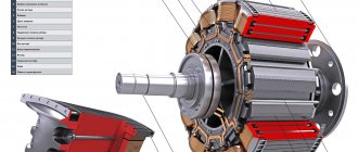
Powering the rotor with direct current: process features
In order for the magnetic field in the rotor not to change direction, its coil must be powered by a direct current of the same polarity. Current is supplied to the rotating coil through carbon brushes and commutator rings.
To power the rotor winding with direct current, two methods are used: self-excitation and excitation from an external source (usually from a battery).
Rice. 3.14. Toothed generator rotor.
Generator Excitation: Understanding the Definition
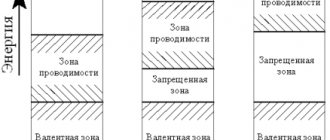
Excitation of the generator is a process that occurs on the basis of magnetomotive force. It carries out the process of inducing a magnetic field, which, in turn, produces the process of generating electricity. To excite the first generation generators, special DC rotators were used, which are also called exciters. Their winding received DC power from another generator, which is usually called a sub-exciter. All components are placed on one shaft, and their rotation occurs synchronously.
Generator field winding: familiarization with the definition
The generator excitation winding is one of the main structural elements of a synchronous generator. It receives power from a source providing direct current. Most often, the source function is performed by an electronic voltage generator. Such regulators are used in new models operating on the basis of a self-exciter. And self-excitation, in turn, is based on the fact that the initial excitation occurs with the help of the residual magnetism of the magnetic circuit of a synchronous generator (SG). It is important to understand that alternating current energy comes precisely from the SG stator winding, transforming it into direct current energy.
What is the generator excitation winding used for?
The rotor winding is excited by a direct current source. The rotor rotates with the help of the prime mover, thereby the magnetic field created in the rotor also rotates with it at the same speed. Now the magnetic field lines cross the stator winding located around the rotor. As a result, an alternating electromotive force (emf) is formed in the winding.
Generator excitation coil: introduction to the definition
The generator field coil is a special electromagnet that is used to generate an electromagnetic field in electromagnetic machines. It consists of a coil and a wire through which current flows. If we take rotating machines as an example, then the excitation coils are wound on a special iron magnetic core. It is the latter that performs the function of directing the magnetic field line. The magnetic circuit includes two main components:
- The stator is stationary.
- Rotor - rotates around the stator.
The magnetic field lines continuously pass from the stator to the rotor and back. The field coils can be located either on the stator or on the rotor.