The first thing to do is take a piece of paper, a pencil and a multimeter. Using all this, ring the windings of the transformer and draw a diagram on paper. This should look something very similar to Figure 1.
The winding terminals in the picture should be numbered. It is possible that there will be much fewer outputs, in the simplest case there are only four: two outputs of the primary (network) winding and two outputs of the secondary winding. But this does not always happen; more often there are several more windings.
Some conclusions, although they exist, may not “ring” with anything. Are these windings broken? Not at all, most likely these are shielding windings located between other windings. These ends are usually connected to a common wire - the “ground” of the circuit.
Therefore, it is advisable to record the winding resistances on the resulting diagram, since the main goal of the study is to determine the network winding. Its resistance, as a rule, is greater than that of other windings, tens and hundreds of Ohms. Moreover, the smaller the transformer, the greater the resistance of the primary winding: the small diameter of the wire and the large number of turns have an effect. The resistance of the step-down secondary windings is almost zero - a small number of turns and a thick wire.
Rice. 1. Diagram of transformer windings (example)
Let's assume that we managed to find the winding with the highest resistance, and we can consider it a network winding. But you don’t need to plug it into the network right away. To avoid explosions and other unpleasant consequences, it is best to perform a test run by connecting in series with the winding a 220V light bulb with a power of 60...100W, which will limit the current through the winding to 0.27...0.45A.
The power of the light bulb should approximately correspond to the overall power of the transformer. If the winding is determined correctly, then the light bulb does not light up; in extreme cases, the filament glows slightly. In this case, you can almost safely connect the winding to the network; for starters, it’s better to use a fuse for a current of no more than 1...2A.
If the light bulb burns brightly enough, then this may be a 110...127V winding. In this case, you should ring the transformer again and find the second half of the winding. After this, connect the halves of the windings in series and turn them on again. If the light goes out, then the windings are connected correctly. Otherwise, swap the ends of one of the found half-windings.
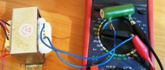
So, we will assume that the primary winding has been found and the transformer has been connected to the network. The next thing you need to do is measure the no-load current of the primary winding. For a working transformer it is no more than 10...15% of the rated current under load. So for the transformer, the data of which is shown in Figure 2, when powered from a 220V network, the no-load current should be in the range of 0.07...0.1A, i.e. no more than one hundred milliamps.
Rice. 2. Transformer TPP-281
How to measure the no-load current of a transformer
The no-load current should be measured with an AC ammeter. In this case, at the moment of connection to the network, the ammeter leads must be short-circuited, since the current when the transformer is turned on can be a hundred or more times higher than the rated one. Otherwise, the ammeter may simply burn out. Next, open the ammeter leads and look at the result. During this test, let the transformer operate for 15...30 minutes and make sure that no noticeable heating of the winding occurs.
The next step is to measure the voltage on the secondary windings without load - open circuit voltage. Let's assume that the transformer has two secondary windings, and the voltage of each is 24V. Almost what is needed for the amplifier discussed above. Next, we check the load capacity of each winding.
To do this, you need to connect a load to each winding, ideally a laboratory rheostat, and by changing its resistance, ensure that the voltage on the winding drops by 10-15%. This can be considered the optimal load for a given winding.
Along with the voltage measurement, the current is measured. If the indicated voltage reduction occurs at a current of, for example, 1A, then this is the rated current for the winding under test. Measurements should begin by setting the rheostat slider R1 to the right position according to the diagram.
Figure 3. Test circuit for transformer secondary winding
Instead of a rheostat, you can use light bulbs or a piece of a spiral from an electric stove as a load. You should start measuring with a long piece of a spiral or by connecting one light bulb. To increase the load, you can gradually shorten the spiral by touching it with a wire at different points, or increasing the number of connected lamps one by one.
To power the amplifier, one winding with a midpoint is required (see the article “Transformers for UMZCH”). We connect two secondary windings in series and measure the voltage. It should be 48V, the connection point of the windings will be the midpoint. If, as a result of the measurement, the voltage at the ends of the windings connected in series is zero, then the ends of one of the windings should be swapped.
In this example, everything worked out almost successfully. But more often it happens that the transformer has to be rewound, leaving only the primary winding, which is almost half the battle. How to calculate a transformer is a topic for another article; here we only talked about how to determine the parameters of an unknown transformer.
Source: electric.info
In modern technology, transformers are used quite often. These devices are used to increase or decrease the parameters of alternating electric current. The transformer consists of an input and several (or at least one) output windings on a magnetic core. These are its main components. It happens that the device fails and there is a need to repair or replace it. You can determine whether the transformer is working properly using a home multimeter on your own. So, how to test a transformer with a multimeter?
Basics and operating principle
The transformer itself is an elementary device, and its operating principle is based on the two-way transformation of the excited magnetic field. Typically, a magnetic field can be induced exclusively using alternating current. If you have to work with a constant, you must first transform it.
A primary winding is wound around the core of the device, to which an external alternating voltage with certain characteristics is supplied. Next come it or several secondary windings in which an alternating voltage is induced. The transmission coefficient depends on the difference in the number of turns and the properties of the core.
Operating principle and purpose
The main purpose of a transformer is to convert or reduce electrical voltage. Depending on the design and purpose, transformers change the current rating, voltage, or convert the pulse to the required value.
The operation of a transformer is based on the principle of the formation of a magnetic field during the interaction of a metal core and a constant voltage. When a voltage of 220 V is connected, the current moves through the primary winding of the transformer, forming a magnetic field. Next, the current enters the secondary winding, the number and pitch of which is much smaller. A strong resistance is created, which is smoothed out due to the influence of magnetic fluxes. Thus, in the secondary winding, the voltage is greatly underestimated, resulting in a lower number output voltage.
Varieties
Today you can find many types of transformer on the market. Depending on the design chosen by the manufacturer, a variety of materials can be used. As for the shape, it is selected solely for the convenience of placing the device in the body of the electrical appliance. The design power is affected only by the configuration and material of the core. In this case, the direction of the turns does not affect anything - the windings are wound both towards and away from each other. The only exception is the identical choice of direction if several secondary windings are used.
To check such a device, a conventional multimeter is sufficient, which will be used as a current transformer tester. No special devices are required.
Check procedure
Testing a transformer begins with identifying the windings. This can be done using markings on the device. Pin numbers, as well as their type designations, should be indicated, which allows you to establish more information in reference books. In some cases there are even explanatory drawings. If the transformer is installed in some kind of electronic device, then the electronic circuit diagram of this device, as well as a detailed specification, can clarify the situation.
So, when all the conclusions are determined, it’s the tester’s turn. With its help, you can identify the two most common faults - a short circuit (to the housing or an adjacent winding) and a winding break. In the latter case, in ohmmeter mode (resistance measurement), all windings are called back one by one. If any of the measurements shows one, that is, infinite resistance, then there is a break.
There is an important nuance here. It is better to check on an analog device, since a digital one can give distorted readings due to high induction, which is especially typical for windings with a large number of turns.
Examination
Checking the transformer for operability and output voltage must begin with a visual inspection. On the body of many modern and old-made elements, a schematic diagram is applied. It contains information about the input and output contacts, the number of turns of the primary and secondary windings, and the values of the output voltages. If this information is not available, you need to ring the transformer.
Many novice radio amateurs are faced with the problem of how to ring a pulse transformer with a multimeter. Further recommendations will be given using this particular device as an example.
Turn-to-turn short circuit
The most important test. It is prohibited to connect unknown transformers found somewhere without a short circuit test. The interturn short circuit cannot be determined using a multimeter. The reason for this lies in the breakdown of two adjacent windings and their connection to each other.
When testing the resistance, it will remain unchanged (if there is no break before the short circuit). Therefore, the transformer is checked visually. Any darkening, swelling, melting of insulation or carbon deposits on the paper can be considered a result of a short circuit. Melting and carbon deposits occurred due to heating of the winding under load. When the primary winding is shorted between turns, the current passes through fewer turns, which creates a load and heat. Short circuit can also be identified by the smell of burning.
If the external appearance of the device does not have any defects in the insulating coating, you can begin the next check.
Search for windings
This test is necessary if the element was not initially connected to the electrical circuit of the instrument or device. The primary winding of the transformer has a larger number of turns, since it is supplied with high voltage. This means that the resistance should be much greater. The input of the primary winding is always located at the top of the device, the secondary terminals at the bottom. To search you need:
Next you need to find the outputs of the secondary coils. This is done according to the same principle. If there are more than 2 outputs, then it is necessary to measure each pair. The resulting values are also saved.
Now you need to verify the results. The leads with the highest resistance will indicate the input primary winding. The remaining pairs will be output contacts.
Integrity
Determining integrity is necessary to find out if there is an open circuit in the transformer circuit. The previous check helped clarify which contacts are incoming and outgoing. Now we need to determine their integrity. To do this you need:
A thermal resistor is needed to shut down the circuit during overheating. It can fail due to high load without passing high voltage into the circuit.
Determining the magnitude of the incoming voltage
This test will help you find out whether the element can be operated from a household electrical network or whether it is designed for voltages of other values. To determine the current value it is necessary:
If the lamp does not light up, this indicates that the transformer is designed to operate on a 220-volt network. The burning of a lamp of any incandescence will indicate operation from currents of other magnitudes.
Output voltage measurement
After carrying out all the tests for the integrity of the pulse transformer, you can proceed to connecting it to electrical voltage and measuring the output voltage. To do this you need:
If the transformer body has markings for the magnitude of the output voltages, then when measuring they should be 5–20% higher. This is done to reserve power for subsequent connection to the diode bridge.
Determination of interturn short circuit
Another common failure of transformers is interturn short circuit. It is almost impossible to check a pulse transformer for such a malfunction with just a multimeter. However, if you attract your sense of smell, attentiveness and sharp vision, the problem can well be solved.
A little theory. The wire on the transformer is insulated exclusively with its own varnish coating. If an insulation breakdown occurs, the resistance between adjacent turns remains, as a result of which the contact area heats up. That is why the first step is to carefully inspect the device for streaks, blackening, burnt paper, swelling and a burning smell.
Next, we try to determine the type of transformer. Once this is achieved, you can look at the resistance of its windings using specialized reference books. Next, switch the tester to megohmmeter mode and begin measuring the insulation resistance of the windings. In this case, the pulse transformer tester is a regular multimeter.
Each measurement should be compared with that indicated in the reference book. If there is a discrepancy of more than 50%, then the winding is faulty.
If the resistance of the windings is not indicated for one reason or another, the reference book must provide other data: the type and cross-section of the wire, as well as the number of turns. With their help, you can calculate the desired indicator yourself.
Checking household step-down devices
It is worth noting the moment of checking classic step-down transformers with a multimeter tester. They can be found in almost all power supplies that reduce the input voltage from 220 Volts to the output voltage of 5-30 Volts.
The first step is to check the primary winding, which is supplied with a voltage of 220 Volts. Signs of a primary winding malfunction:
- the slightest visibility of smoke;
- the smell of burning;
- crack.
In this case, the experiment should be stopped immediately.
If everything is normal, you can proceed to measurements on the secondary windings. You can touch them only with the tester contacts (probes). If the results obtained are less than the control ones by at least 20%, then the winding is faulty.
Unfortunately, such a current block can be tested only in cases where there is a completely similar and guaranteed working block, since it is from it that the control data will be collected. It should also be remembered that when working with indicators of the order of 10 ohms, some testers may distort the results.
No-load current measurement
If all tests have shown that the transformer is fully operational, it would not be amiss to conduct another diagnostic - for the no-load current of the transformer. Most often it is equal to 0.1-0.15 of the nominal value, that is, the current under load.
To carry out the test, the measuring device is switched to ammeter mode. Important point! The multimeter should be connected to the transformer under test in a short-circuited manner.
This is important because when electricity is supplied to the transformer winding, the current increases to several hundred times the rated current. After this, the tester probes open and the indicators are displayed on the screen. It is they that display the value of the current without load, the no-load current. In a similar way, indicators are measured on the secondary windings.
To measure voltage, a rheostat is most often connected to the transformer. If you don’t have it at hand, a tungsten spiral or a series of light bulbs can be used.
To increase the load, increase the number of bulbs or reduce the number of turns of the spiral.
As you can see, you don’t even need any special tester to check. A completely ordinary multimeter will do. It is highly desirable to have at least an approximate understanding of the operating principles and structure of transformers, but for successful measurements it is enough just to be able to switch the device to ohmmeter mode.
Source: evosnab.ru
Simple ways to calculate the power of a power transformer
With the power of a step-down transformer, things are a little more complicated, but there are still some simple techniques. The most accessible way to determine this characteristic is to measure the diameter of the wire in the secondary winding. To do this you will need a caliper, a calculator and the information below. First, the diameter of the wire is measured. For example, let's take a value of 1.5 mm. Now you need to calculate the cross-section of the wire. To do this, you need to square half the diameter (radius) and multiply by the number “pi”. For our example, the cross-section will be about 1.76 square millimeters. Next, for the calculation you will need the generally accepted value of current density per square millimeter of conductor. For household step-down transformers, this is 2.5 amperes per square millimeter. Accordingly, a current of about 4.3 A can “painlessly” flow through the second winding of our sample. Now we take the previously calculated voltage of the secondary winding and multiply it by the resulting current. As a result, we get the approximate value of the power of our transformer. At 12 V and 4.3 A, this parameter will be around 50 W. The power of an “unnamed” transformer can be determined in several other ways, however, they are more complex. Those interested can find information about them on the Internet. Power is determined by the cross-section of the transformer windows, using calculation programs, as well as by the nominal operating temperature.
How to connect an unknown transformer to the network
Before connecting the transformer to the network, you need to determine the primary winding of the transformer and test its primary and secondary windings with an ohmmeter.
In step-down transformers, the resistance of the mains winding is much greater than the resistance of the secondary windings and can differ by a hundred times.
There can be several primary (network) windings, or a single winding can have taps if the transformer is universal and designed for use at different mains voltages.
In two frame transformers on core magnetic cores, the primary windings are distributed over both frames.
protected by fuse
When testing transformers, you can use the diagram below. If the primary voltage of the transformer is incorrectly , the FU fuse will protect the network from short circuit and the transformer from damage.
Video: A simple way to diagnose a power transformer
When the type of power transformer is unknown, especially since we do not know its passport data, an ordinary pointer tester and a simple device in the form of an incandescent lamp come to the rescue.
What is a transformer and how to check it
Without this electrical device, electricity consumers would not be able to charge car batteries or connect energy-saving light sources. An electrical product reduces the stationary voltage to the required level. The device is made on the basis of electromagnetic induction. Sold in specialized stationary retail outlets and online stores. A 12-volt step-down transformer is purchased by drivers, summer residents, and owners of country houses and cottages for the installation of an intra-house low-voltage lighting network.
How to choose a fuse for a transformer
We calculate the fuse current in the usual way:
I – current for which the fuse is designed (Ampere), P – overall power of the transformer (Watt), U – network voltage (
The closest value is 0.25 Ampere.
determination of transformer primary voltage
Circuit for measuring the no-load current (IO) of the transformer. The XX current of the transformer is usually measured to exclude the presence of short-circuited turns or to ensure that the primary winding is connected correctly.
When measuring the XX current, you need to gradually increase the supply voltage. In this case, the current should increase smoothly. When the voltage exceeds 230 volts, the current usually begins to increase more sharply. If the current begins to increase sharply at a voltage significantly less than 220 Volts, it means that either you have chosen the primary winding incorrectly, or it is faulty.
| Power, W) | Current XX (mA) |
| 5 — 10 | 10 — 200 |
| 10 -50 | 20 — 100 |
| 50 — 150 | 50 — 300 |
| 150 — 300 | 100 — 500 |
| 300 — 1000 | 200 — 1000 |
Approximate currents of XX transformers depending on power. It should be added that the currents of XX transformers, even of the same rated power, can differ greatly. The higher the induction values included in the calculation, the greater the XX current.
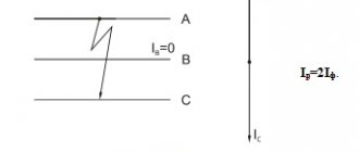
Connection diagram for determining the number of turns per volt.
You can select a ready-made transformer from among the unified types TN, TA, TNA, TPP and others. And if you need to wind or rewind the transformer to the desired voltage, what should you do?
Then you need to select a power transformer from an old TV that is suitable in terms of power, for example, the TS-200 transformer and the like.
It is necessary to clearly understand that the greater the number of turns in the primary winding, the greater its resistance and therefore the less heating and second, the thicker the wire, the greater the current strength can be obtained , but this depends on the size of the core - whether you can place the winding.
What do we do next if the number of turns per volt is unknown?
To do this, you need an LATR, a multimeter (tester) and a device that measures alternating current - an ammeter. At your discretion, we wind the winding over the existing one, the diameter of the wire is any; for convenience, we can simply wind it with an insulated installation wire.
What functions does a transformer perform?
Transformers are widely used in battery chargers.
The main function of transformers is to reduce or increase the voltage of the current supplied to them. These devices are widely used in high-voltage networks that deliver electricity from the point of generation to the end consumer.
In a modern household it is difficult to do without a current transformer. These devices are used in all types of equipment, from refrigerators to computers.
Until recently, the size and weight of household appliances were often determined precisely by the parameters of the transformer, because the basic rule was that the higher the power of the current converter, the larger and heavier it is. To see this, just compare the two types of chargers. Transformers from an old mobile phone and a modern smartphone or tablet. In the first case, we will have a small but weighty charging device, which gets noticeably hot and often breaks down. Pulse transformers are characterized by silent operation, compactness and high reliability. The principle of their operation is that the alternating voltage is first supplied to the rectifier and converted into high-frequency pulses, which are fed to a small transformer.
When repairing equipment at home, there is often a need to independently wind the transformer coil. For this purpose, prefabricated cores are used, which consist of individual plates. The parts are connected to each other by means of a lock, forming a rigid structure. Winding with wire is done using a homemade device that works on the principle of a rotator.
When creating such a transformer, you should remember: the tighter and more neatly the wire is wound, the fewer problems will arise with the operation of such a device.
The turns are separated from each other by a single layer of paper coated with glue, and the primary winding is separated from the secondary by a gap of 4-5 layers of paper. Such insulation will provide protection against breakdowns and short circuits. A correctly assembled transformer guarantees stable operation of the equipment, the absence of annoying hum and overheating.
Formula for calculating transformer turns
P=U2*I2 (transformer power)
Sheart(cm2)= √ P(va) N=50/S
I1(a)=P/220 (primary winding current)
W1=220*N (number of turns of the primary winding)
W2=U*N (number of turns of the secondary winding)
D1=0.02*√i1(ma) D2=0.02*√i2(ma) K=Swindow/(W1*s1+W2*s2)
50/S is an empirical formula where S is the area of the transformer core in cm2 (width x thickness), and is believed to be valid up to a power of about 1kW. Having measured the area of the core, we estimate how many turns need to be wound at 10 volts; if this is not very difficult, without disassembling the transformer we wind the control winding through the free space (slot).
We connect the laboratory autotransformer to the primary winding and apply voltage to it, turn on the control ammeter in series, gradually increase the voltage with the LATR until the no-load current begins to appear.
If you plan to wind a transformer with a fairly “hard” characteristic, for example, it could be a transmitter power amplifier in SSB, telegraph mode, where rather sharp load current surges occur at high voltage (2500 -3000 V), for example, then the no-load current The transformer is set to about 10% of the maximum current, at the maximum load of the transformer. Having measured the resulting voltage of the wound secondary control winding, we calculate the number of turns per volt.
How to ring a transformer or how to determine the windings of a transformer.
16 Feb 2016 | Section: Radio for home
Hello, dear readers of the site sesaga.ru. At the beginning of their studies in radio electronics, beginning radio amateurs, and not only radio amateurs, have a lot of questions related to the continuity or determination of transformer windings . This is good if the transformer has only two windings. And if there are several of them, and each winding also has several outputs. Here you just shout guard. In this article I will tell you how you can determine the windings of a transformer by visual inspection and using a multimeter.
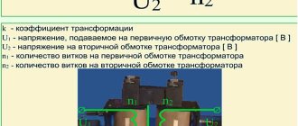
As you know, transformers are designed to transform
alternating voltage of one magnitude into alternating voltage of another magnitude.
The most common transformer has one primary
and one
secondary
winding. The supply voltage is supplied to the primary winding, and the load is connected to the secondary winding. In practice, most transformers can have several windings, which makes it difficult to determine them.
The most important parameters of power transformers
What do you need to know about a transformer in order to use it correctly and, most importantly, safely for your purposes? Most often this involves repairing some household appliances or making your own crafts powered by low voltage. And you need to know the following about the transformer lying in front of us:
- Which terminals should mains power be supplied to (230 volts)?
- From which terminals should the undervoltage be removed?
- What will it be (12 volts, 24 or others)?
- How much power can the transformer produce?
- How not to get confused if there are several windings, and, accordingly, paired terminals?
It is quite possible to calculate all these characteristics even when there is absolutely no information about the brand and model of the power transformer. To complete the work you will need the simplest tools and consumables:
- multimeter with ohmmeter and voltmeter functions;
- soldering iron;
- electrical tape or heat shrink tubing;
- mains plug with wire;
- a pair of ordinary wires;
- incandescent lamp;
- calipers;
- calculator.
You will also need some kind of wire stripping tool and a minimum soldering kit - solder and rosin.
Identification of windings by visual inspection.
When visually inspecting a transformer, pay attention to its outer protective insulation layer, because some models depict an electrical circuit on the outer layer indicating all windings and terminals; For some models, the winding terminals are only marked with numbers. You can also find old domestic transformers, on the outer layer of which they indicate markings in the form of a digital code, according to which reference books for radio amateurs contain all the information about a specific transformer.
If you come across a transformer without identification marks, then pay attention to the diameter of the winding wire with which the windings are wound. The diameter of the wire can be determined by the protruding terminals of the ends of the windings, released for fastening to the contact petals located on the elements of the transformer frame. As a rule, the primary winding is wound with a wire of a smaller cross-section in relation to the secondary. The diameter of the secondary winding wire is always larger.
An exception may be step-up transformers operating in voltage and current converter circuits. Their primary winding is made of thick wire, as it generates high voltage in the secondary winding. But such transformers are very rare.
In the manufacture of transformers, the primary winding is usually wound first. It can be easily identified by the protruding ends of the winding terminals located closer to the magnetic core. The secondary winding is wound on top of the primary, and therefore the ends of its terminals are located closer to the outer layer of insulation.
In some models of network transformers used in power supplies for household radio equipment, the windings are placed on a plastic frame, divided into two parts: one part contains the primary winding, and the other contains the secondary winding. A flexible mounting wire is soldered to the terminals of the primary winding, and the terminals of the secondary winding are left in the form of a winding wire.
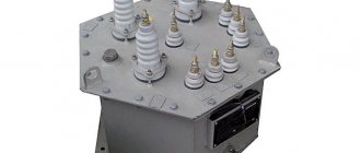
Voltage transformer connection diagrams
General information
Voltage transformers, as a rule, are a type of transformer that are designed not to transmit power, but to galvanically separate the high-voltage side from the low-voltage side.
Such transformers are designed to power measuring and control devices. On the “high” side of various voltage transformers, naturally, the voltage can be different, it can be 6000, 35,000 volts and even much more, but on the “low” side (on the secondary winding) it does not exceed 100 volts.
This is very convenient for unifying control devices. If you make measuring and control devices, and these are mainly relays, for high voltage, then, firstly, they will be very large, and secondly, very dangerous to maintain.
The transformation ratio is indicated on the transformer itself and can look like Ku = 6000/100, or simply 35000/100. Dividing one number by another, we get in the first case this coefficient is 60, in the second 350.
These transformers are available as “dry” transformers, in which electrical cardboard is used as insulation. They are usually used for voltages up to 1000 volts. Example NOS-0.5. Where, H means voltage, meaning a voltage transformer, O - single-phase, C - dry, 0.5 - 500 volts (0.5 kV). And also oil ones: NTMI, NOM, 3NOM, NTMK, in which oil plays the role of both an insulator and a cooler. And cast, to be precise, with cast insulation (3NOL - three-winding single-phase voltage transformer with cast insulation), in which all windings and the magnetic circuit are filled with epoxy resin.
Voltage transformer design
Like all transformers, as mentioned above, this type of transformer has both primary windings (high voltage) and secondary windings (low voltage). There are single-phase and three-phase voltage transformers.
Each of them has a magnetic circuit, which is subject to fairly high requirements. The fact is that the greater the dissipation of the magnetic flux in such a transformer, the greater the measurement error. By the way. Depending on the error, transformers are classified into different accuracy classes (0.2; 0.5; 1; 3). The higher the number, the greater the measurement error.
For example, a transformer with an accuracy class of 0.2 can allow an error of no more than 0.2% of the measured voltage value, and, accordingly, an accuracy class of 3 - no more than 3%.
The designations on the diagrams and the natural design can be very different from each other.
A single-phase two-winding transformer is shown in the figure as it actually looks.
In the diagrams it is designated as:
Please note that the transformer is a step-down, there are fewer turns in the secondary winding than in the primary, and this is reflected visually in the diagram in this case, although this is not always done. In addition, the beginnings and ends of the windings are indicated on the diagram and on the transformer itself. Primary windings are designated by large (capital) letters A and X. Secondary - small (lowercase) letters a and x.
There are also three-winding single-phase transformers that have two secondary windings. One of which is the main one, and the second is additional. The additional winding serves to control insulation and has the abbreviation KIZ. The markings of the terminals of this winding are as follows: ad - the beginning of the winding, xd - the end of the winding.
Three-phase transformers are available with two types of magnetic cores: three-rod and five-rod.
Beginnings and endings are designated slightly differently here. On the primary windings, the beginnings are designated by the letters A, B and C according to the phases to which they will be connected, and the ends by the letters X, Y and Z. The secondary windings, respectively, by small letters a, b, c and x, y, z.
The magnetic fluxes created by the AX, BY, CZ coils compensate each other under normal operating conditions. But in the event of a breakdown of one of the phases to the ground, too much imbalance is created in the magnetic cores and part of the flux will be looped through the air, which creates strong heating of the transformer due to an increase in the rated current in the windings. Additional rods are precisely designed to take over the resulting unbalanced flows and prevent overheating of the transformer. At the same time, additional windings are wound in it, but more on that later.
Connection diagrams for voltage transformer windings
The simplest way to measure phase-to-phase voltage is to connect a single-phase two-winding voltage transformer according to the diagram shown in the figure on the left.
In this case, at the ends of the secondary winding we have a voltage corresponding to the interphase BC, but reduced taking into account the transformation ratio.
All three phase-to-phase voltages can be measured using two single-phase transformers connected in a certain way.
In three-phase transformers, the primary windings are always connected in a star configuration.
The secondary windings can be connected either in a star or delta configuration.
With the top connection at the output points of the secondary winding, we have the ability to measure phase-to-phase voltages. With a lower connection, according to the so-called open delta circuit, we can detect the fact of a short circuit or wire break in one of the phases on the high side. The terminals are marked 01 and 02, since under normal operating conditions there is no voltage between these points.
To connect the protection relays, as mentioned above, additional windings in three-winding voltage transformers are used. Here is an example of connecting such transformers to a three-phase network. In this case, the ends of the windings are grounded in both the primary and secondary windings.
Here are a few more options for connecting single-phase transformers for measuring phase-to-phase and phase-to-phase voltages, as well as for powering control equipment.
More complex options for connecting voltage transformers containing a larger number of windings are studied in a special electrical engineering course.
Write comments, additions to the article, maybe I missed something. Take a look at the site map, I will be glad if you find anything else useful on my site.
Share link:
Determination of windings by resistance.
When a preliminary analysis of the windings has been carried out, it is necessary to ensure that the conclusions drawn are correct, and at the same time ring the windings to ensure there are no breaks. To do this, we will use a multimeter. If you don’t know how to measure resistance with a multimeter, then read this article.
First, let's ring a regular network transformer, which has only two windings. We switch the multimeter to the “Dial” mode and measure the resistance of the proposed primary and secondary windings. Everything is simple here: whichever winding has the greatest resistance, that winding is the primary winding.
This is explained by the fact that in low-power and medium-power transformers, the primary winding can contain 1000...5000 turns wound with thin copper wire, and can achieve a resistance of up to 1.5 kOhm. Whereas the secondary winding contains a small number of turns wound with thick wire, and its resistance can be only a few tens of ohms.
Now let's ring a transformer that has several windings. To do this, we will use a piece of paper, a pen and a multimeter. On paper we will sketch and write down the resistance values of the windings.
This is done like this: with one multimeter probe we sit on any extreme terminal, and with the second probe we touch the remaining terminals of the transformer in turn and write down the resulting resistance value. The terminals between which the multimeter will show resistance will be the terminals of one winding. If the winding is without middle taps, then the resistance will only be between two terminals. If the winding has one or more taps, then the multimeter will show the resistance between all these taps.
For example. The primary winding may have several taps when the transformer is designed to operate in a network with voltages of 110V, 127V and 220V. The secondary winding can also have one or more taps when they want to receive several voltages from one transformer.
Go ahead. When the first winding and its terminals are found, we move on to searching for the next winding. Using the probe, we again sit on the next free pin, and with the other, we touch the remaining pins one by one and write down the result. And in this way we carry out measurements until all the windings are found.
For example. Between pins with numbers 1
and
2,
the resistance value was 21 Ohms, while between the other terminals the multimeter showed infinity. It follows from this that we have found a winding whose terminals are designated numbers 1 and 2. Let’s draw it like this:
Now we touch the output with a probe 3
, and with another probe we alternately touch the terminals with numbers from 4 to 10. The multimeter showed resistance only between terminals
3
,
4
and
5
.
Moreover, between pins 3 and 4 the resistance value was 6 ohms, and between a pair of pins 3
,
5
and
4
,
5
it was 3 ohms.
From here we conclude that this winding has a tap in the middle, i.e. pairs 3, 5 and 4, 5 are wound with an equal number of turns, and that two identical voltages are removed from this winding relative to the common terminal 5
. Let's draw it like this:
Let's take the next measurement. Between pins 6
and
7
the resistance value was 16 Ohms. Let's draw it like this:
Well, between the conclusions 9
and
10
the resistance was 270 Ohms. And since among all the windings this one turned out to have the highest resistance value, then it is the primary one. Let's draw it like this:
Conclusion 8
, to which the yellow-green core is soldered, did not ring in any way, so we boldly say that this is a shielding winding (screen), which is wound on top of the primary one in order to eliminate the influence of its magnetic field on other windings. As a rule, the shielding winding is connected to the housing of the radio equipment.
As a result, we got four windings, of which one is network and three are step-down. The shielding winding is indicated by a dotted line and is located parallel to the core. And now, based on the results obtained, we will draw an electrical circuit of the transformer.
Now all that remains is to apply voltage to the primary winding and measure the output voltages. However, there is one point that you need to know if you doubt the correctness of the determination of the primary (network) winding.
Everything is simple here: in order not to burn the transformer winding and limit unwanted current through it, you need to turn on an incandescent lamp in series with this winding at a voltage of 220V and a power of 40 - 100 W. If the winding is determined correctly, then the lamp filament should not burn or barely smolder. If the lamp burns brightly enough, then there is a possibility that the mains winding of the transformer is designed for a supply voltage of 110 - 127V or you have dialed it incorrectly.
Calculation of transformers - Amateur Radio ABC
AC mains voltage is most often used to power various devices. But since it is usually too high for most devices, it has to be lowered. This can be done in two ways: using a quenching resistor (capacitor) or using a transformer.
The only drawback of damping elements is the extremely low efficiency of power supplies based on them. The current consumed by such power supplies from the network is equal to the load current, i.e. if the network voltage is 220 V and the device supply voltage is 11 V, then only 11/220 = 1/20 of the energy goes to power the device, and the rest 19/20 - to heat the quenching resistor or to create an alternating electrostatic field inside the quenching capacitor.
Therefore, it makes sense to use “quenching” power supplies only in micropower devices that consume such a small current that it can be ignored. In such devices, the damping element makes it possible to reduce overall dimensions (transformers are never small) and their cost. But you need to take into account that the damping elements do not provide galvanic isolation from the mains voltage, so reaching with your fingers into a switched-on device is life-threatening!
A transformer is an inductor and works on the same principle. The transformer provides galvanic isolation of the input and output voltages - the resistance between the input and output wires is close to infinity on both direct and alternating current. This is possible because the “connecting link” between the input and output (primary and secondary, respectively) windings of the transformer is an electromagnetic field, but it does not carry (transmit) current. Alternating current applied to the primary coil of a transformer creates an alternating magnetic field in the transformer core, which moves around the coil (primary winding). If there is one more (or several) coils in the path of this field, then an alternating voltage will be induced in them by the electromagnetic field, the magnitude of which depends on the field strength (it is constant and depends on the size of the transformer core, and this size is unchanged) and the number of turns in the secondary transformer windings, which can be wound as many as you like. By rectifying the voltage induced by the electromagnetic field into the secondary windings of the transformer with diodes, it can be used to power various devices.
The transformer windings are coils of wire, so their DC resistance is very low. For example, a 100-watt transformer has a resistance of the primary (mains) winding of 10...15 Ohms. If this winding is connected to a DC network with an amplitude of 220 V, then the power P = U2: R released on it will exceed 4000 W and the winding will instantly burn out. Therefore, it is impossible to apply constant voltage to the transformer windings! But since any winding of any transformer is, first of all, an inductance coil, when an alternating voltage is applied to it, its resistance increases sharply (inductive reactance begins to manifest itself, depending on the inductance of the coil, and at low frequencies it tends to zero, and at high levels - to infinity). The resistance of the primary winding of the above-mentioned AC transformer is approximately 5 kOhm, and the power released on the winding does not exceed 10 W. By increasing the number of turns of the primary winding, you can increase its inductance, and the no-load current (1ХХ; for the transformer considered here it is equal to U/R = 220: 5000 = 44 mA) will decrease even more; but at the same time, the strength of the electromagnetic field in the core will also decrease, i.e., more turns will also need to be wound in the secondary windings; wire is now expensive, and the size of the transformer frame is too small.
Surely all readers of this book have seen a transformer, so its appearance will not be described here. You just need to know that it consists of three parts: a plastic or getinax frame, insulated copper wire windings wound on the frame, and a magnetic circuit (water flows through the water supply system, and a magnetic field flows through the magnetic circuit) made of special magnetic ferrite ceramics or a layer of thin iron plates Since the magnetic core of the transformer is made of easily magnetized (and demagnetized) materials, thanks to it the inductance of the transformer coils with an inserted magnetic core is much greater than without it (tens of times), thanks to this the number of turns of the transformer can also be reduced by tens of times. The main parameter of a magnetic circuit - magnetic permeability - shows how many times the number of turns of a coil on this magnetic circuit can be reduced compared to a coil that does not have it at all, so that the coils have the same inductance. For iron magnetic cores it is rarely more than 100, for ferrites it reaches 2000.
It is strictly prohibited to turn on a transformer with the magnetic core removed or not inserted into the network! In this case, the inductance of the windings turns out to be too small, and significant current flows through them, which can damage the transformer and (or) the current source.
Basic rules for making a “homemade” or rewinding industrial transformer:
•The wire (wire) for the windings must be insulated - usually copper “transformer” wire is used, also called “screened”, coated with varnish in one (PEL-1) or two (PEL-2) layers. The second is better, but it is thicker (with the same diameter of the copper core) and more expensive. Instead of copper wire, aluminum is sometimes used (it bends easier and weighs less), but the resistance of aluminum is 1.6 times greater than that of copper, i.e., to obtain the same current, the aluminum wire must be *Jl.6 times thicker than copper . In addition, aluminum, unlike copper, is very difficult to solder.
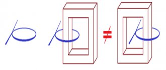
•The closer the winding is located to the core, the greater its inductance and the lower the wire consumption (with a constant number of turns), so the primary (network) winding should be wound first.
•Windings must be wound in one direction. If, for example, you started winding the coil “clockwise” (“the hole” for the magnetic circuit is “staring” you in the face), wound 100 turns, and then “changed your mind” and wound 900 turns “counterclockwise”, then the total “length "The coils will not have 1000, but 800 turns. The remaining 200 turns are “harmful ballast” and do not affect the inductance of the coil. But you can move each subsequent turn relative to the previous one to the left/right without any restrictions - you just need to strive to ensure that the thickness of the resulting coil is the same in all places, and where it is smaller, wind more layers of wire.
•The wire insulation is very thin and far from ideal. Therefore, if you are winding a high-voltage winding (more than 100 V), then periodically between the layers of wire you need to lay special transformer paper or, if you don’t have it, paper or film from “unnecessary”
high-voltage (400 V or more) “disassembled” capacitors. In the latter case, you need to carefully remove the foil - the capacitor linings. It is advisable to lay “capacitor” insulators between each layer of the winding, transformer paper - 1 layer per 2 layers of wire. Between the high-voltage and low-voltage windings it is necessary to lay a layer of insulation with a thickness of at least 0.5 mm. Cellophane and other fusible films cannot be used.
• Windings with wire with a diameter of 0.3 mm or more must be wound “turn to turn”; with wire of a smaller diameter, it is also possible “in bulk”. There is very little space on the transformer coil, and when winding in bulk, it is used very irrationally. But since it is very difficult to wind “turn to turn” with wire with a diameter of less than 0.3 mm, it can also be wound “in bulk”. The tension of the wire when winding should be maximum, but such that it does not break.
• If the wire breaks during winding or if you need to continue winding with another wire, do not save time, heat up the soldering iron and solder the ends! Of course, it is very tempting to simply twist the ends of the wire together without soldering them, but over time the exposed and twisted ends will oxidize and the contact will be broken. Do you want to rewind the transformer for this reason? The soldered ends of the winding wires must be carefully insulated.
• You can use a sharp knife to clear the varnish insulation from the ends of the wire (“stripping the ends”) so that it can be tinned and soldered. In general, a knife with a blade length of no more than 10 cm (preferably folding) is an indispensable assistant for a radio amateur. But a wire with a diameter of less than 0.15 mm can only be torn with a knife. Therefore, you have to clean it using a chemical method: take a tablet of hydrogen peroxide (hydroperite), place the end of the wire on it and quickly move the heated soldering iron along the wire. Under the influence of high temperature, hydroperite decomposes into water and atomic oxygen, the latter softens the varnish, which is scraped off with a soldering iron tip. Instead of hydroperite, you can take an aspirin tablet, but it decomposes into rather asphyxiating substances. Acetone and other solvents do not dissolve varnish insulation; You cannot burn varnish in the flame of a match or lighter - after firing, the copper oxidizes and it is impossible to tin such a wire.
Power transformers (those used to power devices) come with two coils (on a U-shaped magnetic core) and with one. “Two-coil” transformers are used very rarely, so they will not be considered here. “Single-coil” ones come with a W-shaped plate and W-shaped tape magnetic core. The latter is easier to assemble/disassemble and also weighs less; but it is very difficult to compress it so that the transformer does not “hum.”
Transformer calculation procedure. The first step is to determine its power: if too much power is taken from the transformer, it may overheat. To calculate, you need to know the device supply voltage
(in volts) and the current consumed by it (in amperes), P = U χ I. If the transformer has several windings, you need to calculate the power consumption from each winding, and then add the resulting numbers.
The main “parameter” of the transformer is the cross-sectional area of the core S. To find it out, you need to measure the width and height of the window (but not the length of the coil!), i.e., the “hole” into which the magnetic circuit is inserted, in centimeters and multiply these numbers .
The maximum permissible load power of a transformer is approximately equal to the square of the cross-sectional area, i.e. Pma)i « S2. This formula is not entirely accurate, but in most cases the “inaccuracy” can be ignored. It is only valid for a frequency of 50 Hz.
The minimum number of turns of the primary winding (the one to which the input voltage is applied) is equal to:
where UBX is input voltage, V (220 V); Wlmin — minimum number of turns, pieces.
With this number of turns, the transformer should not heat up during operation (with the load off). With a connected load that consumes the maximum power for a given transformer, it can heat up by
10...20 °C. With a further increase in power consumption, the transformer heats up sharply.
The number of turns of the secondary winding is calculated by the formula:
where K is a coefficient depending on the power of the transformer (Fig. 3.19);
UBUX - required output voltage, volts;
Rice. 3.19. Dependence of coefficient K on transformer power
The introduction of the K coefficient was necessary due to the fact that not all the power of the primary winding is converted into an electromagnetic field and the smaller the transformer dimensions (overall power), the greater the losses.
Winding wire diameter:
where d is the diameter of the wire without insulation (insulation occupies part of the diameter), mm; I is the current through the winding, A.
If the diameter of the winding wire is known, then the maximum permissible current flowing through it can be found from the formula:
The current flowing through the primary winding of the transformer does not exceed
where P is the overall (maximum) power of the transformer, W;
U is the voltage on the winding, V (220 V).
This formula is needed to correctly select the diameter of the primary winding wire. If there is also one secondary winding, then the maximum current through it is determined by the same formula. You can take a thicker wire - it won’t be worse, but the winding will take up too much space; if you wind the winding with too thin a wire, then its active resistance (it is numerically equal to the output resistance of the transformer winding) will become too large and under load the voltage on the winding will greatly decrease (“sag”), as a result, the winding will heat up intensely. It’s like with resistors: if the same current flows through two resistors (the resistance of the first is R, and the second is twice as much - 2R), then if the power released on R is equal to P, the power released on the resistor 2R will be twice as large , i.e. 2R.
The wound primary winding, if the diameter of the wire is chosen correctly, should occupy exactly half the height of the frame if it is wound “turn to turn”, and a little more if “in bulk”. If the primary winding takes up more space, you will not have room for secondary windings, if less, the overall power of the transformer will decrease. It is equal to:
where U,, d, is the voltage on the primary winding and its diameter;
U2, 12 - voltage and current of the secondary windings.
If the transformer must be designed for a frequency other than 50 Hz, then to determine the number of turns of the primary winding you need to use the formula:
where U is the voltage on the winding, V; f—frequency, Hz; W - amplitude value of magnetic induction, for ferrites W = 0.2...0.3, for iron W » 1.0, for permalloy W and 1.2; Tl; S is the cross-section of the magnetic circuit, cm2.
The number of turns of the secondary winding is calculated using the same formula, but it must automatically be increased by 5...10% in order to compensate for losses in the magnetic core.
As can be seen from the formula, the higher the frequency of the input signal, the fewer turns in the winding. That is, in a higher-frequency transformer, the windings take up much less space. In addition, as the frequency increases, the overall power of the transformer increases - for example, for a ferrite ring with a diameter of 40 mm, the overall power at a frequency of 50 Hz is approximately equal to S2 and does not exceed 1...2 W; at a frequency of 20 kHz, the overall power of the same ring increases to 500 W!
The reason for this is the reduction in pulse duration. At a frequency of 20 kHz, the duration of one half-cycle of the input (output) voltage is 20,000: 50 = 400 times less than at a frequency of 50 Hz. Therefore, the amplitude of the current pulses in the primary and secondary windings of such a transformer can be 400 times greater than that of a 50-Hz transformer, which means that the overall power increases by 400 times.
Therefore, all modern powerful network power supplies are made according to a pulse circuit: the high-voltage network voltage is rectified, smoothed and supplied to a powerful high-voltage generator, which converts a direct voltage of 220 V (more precisely, 310 V - when rectified by a full-wave (bridge) rectifier and smoothed by a capacitor, the voltage “increases" "V2 times - by the way, this effect is actively used in rural areas, where the network voltage is much lower than 220 V, to power incandescent lamps - so that they glow brighter) with small ripples of 50 Hz into alternating voltage with a frequency of 20...50 kHz. This voltage is supplied to the transformer and further, as in a conventional power supply. Despite the fact that a switching power supply contains many more parts than a regular one, it is smaller in both size and price. A 300 W switching power supply can be placed in the housing of a television remote control, and it will cost no more than $10 (cost price). A typical 50 Hz, 300 W transformer weighs about 4 kg, and the now expensive copper accounts for more than 1 kg. Such a transformer (and a cart for carrying it) costs much more than $10.
The maximum operating frequency for most ferrites (iron plate and tape magnetic cores can be used at frequencies up to 0.5...1 kHz) is about 100 kHz, so the optimal operating frequency is
20...50 kHz. The disadvantage of a switching power supply is that there is very high interference at frequencies from operating to several megahertz, so when using them to power UMZCH, the operating frequency must be selected higher, and a low-pass filter with a cutoff frequency of 20 kHz (15...25 kHz) must be installed in the amplifier, because if a person does not hears a signal whose frequency is equal to the operating frequency of the power supply, this does not mean that the amplifier does not amplify this signal. But such a power supply cannot be used to power a device that includes a long-short-wave radio receiver: it is almost impossible to deal with its high-frequency interference.
The diameter of the wire and everything else for high-frequency transformers is calculated using the same formulas as for low-frequency transformers. If you are winding a high-voltage coil on a ferrite ring, then before winding the ring must be wrapped in several layers of special tape or transformer paper cut into strips (width 3...5 mm). Although ferrite is a dielectric (insulator), its breakdown voltage is very low, and you hardly need short circuits in the transformer.
Source: A. S. Koldunov, Amateur Radio ABC. Volume 2. Analog devices. - M.: SOLON-Press, 2004. 288 p. — (Series “SOLON - FOR RADIO AMATEURS” issue 24)
Tweet Like
- Previous post: Memory – Digital technology
- Next entry: Brushless DC motor in the national economy
- Preventing Excessive Power Dissipation in Linear Regulators (0)
- Power regulators for a soldering iron, another diagram (0)
- What is the difference between current and voltage? (2)
- Current and Voltage Relationship (0)
- About frequencies, periods, power, alternating voltages and currents and a little about signals (0)
- Power - basic concepts (0)
- POWER SUPPLY FOR CAR RADIO (0)
Related posts:
How to test a transformer with a multimeter
It is very useful for novice radio amateurs to be able to and know how to test a transformer with a multimeter. Such knowledge is useful because it saves time and money. In most linear power supplies, the lion's share of the cost is the transformer. Therefore, if you happen to have a transformer with unknown parameters in your hands, do not rush to throw it away. Better pick up a multimeter. Also, for some experiments we will need an incandescent lamp with a socket.
In order to more consciously carry out further experiments and experiments, you should understand how a transformer transformer is designed and works. Let's look at this in a simplified form here.
The simplest transformer consists of two windings wound on a core or magnetic circuit. Each winding consists of conductors isolated from each other. And the core is made of thin sheets of special electrical steel, insulated from each other. Voltage is applied to one of the windings, called the primary, and voltage is removed from the second, called the secondary.
When an alternating voltage is applied to the primary winding, since the electrical circuit is closed, a bullet is created in it for the flow of alternating electric current. An alternating magnetic field always forms around a conductor carrying alternating current. The magnetic field is closed and amplified by the magnetic core and induces an alternating electromotive force of EMF in the secondary winding. i 2 flows in it .
This knowledge is not yet enough to fully understand how to test a transformer with a multimeter. Therefore, we will consider a number of useful points.
Transformer connection diagram, how to properly connect it to the circuit.
Topic: how to connect a transformer to an electrical circuit.
The use of power step-down (less often step-up) transformers is widespread. They are a fairly simple and inexpensive solution for the function of converting electrical energy, namely voltage and current. For those who are not particularly familiar with electrical engineering, let me clarify - transformers are an electrical machine consisting of a magnetic circuit of a certain shape, which contains windings of insulated wire (most often copper). Depending on the number of turns on the transformer and its cross-section, the voltage and current that is converted depends.
The simplest version of the transformer contains two windings. The input winding is called primary, and the output winding is called secondary. Initially, each transformer is calculated for its power, voltage, current, and frequency. Most often you can find a regular step-down transformer, in which the input winding is designed for a voltage of 220 volts, and the secondary winding is designed for the voltage that is used by one or another device (the most common are 3, 5, 9, 12, 24 volts). The voltage depends on the number of turns, and the current depends on the diameter of the winding wire.
The transformer connection diagram is quite simple. Power is supplied to the input (AC voltage). If this is a regular step-down trans, designed for standard mains voltage, then connect 220 volts. Polarity doesn't matter here. Usually on the electrical device itself it is written where it is, what winding it is, and how many volts it is designed for. Input wires (or outputs, terminals) are usually made well insulated, located separately from the output wires. In principle, it is easy to understand which pins correspond to the input.
If you come across a power transformer that does not have a clear indication or label where its input terminals, outputs, wires are, and you know for sure that it is 220 volts, then you can simply call the primary winding with a tester or multimeter. So, first we visually determine which outputs are most similar to the input. Next, we begin to measure the resistance of the windings. Since the primary winding is designed for a higher voltage (220 volts), it means it will have the greatest resistance relative to all others. For example, for most step-down transformers, approximately the size of an adult’s fist, the resistance of the input, primary winding will be in the range of 10-1000 ohms. The larger the transformer, the lower the resistance on its input winding.
The secondary winding of a power step-down transformer in a simple version has two outputs (wires, terminals). It is wound with a wire of larger diameter compared to the primary winding. There will be a reduced alternating voltage at its terminals (when power is applied to the input). Most devices require a constant low-voltage voltage, and since alternating voltage comes out of the secondary winding, in most cases it is connected to a diode rectifier bridge, which converts the alternating voltage into direct voltage.
Some electrical devices require several different low voltage voltages. In this case, power step-down transformers are installed, which have one input winding (primary), designed for 220 or 380 volts, and several output windings (secondary). Or there may be a secondary winding with a midpoint. That is, the output winding of an electric machine (trans) has 3 wires (one wire common to two identical windings, and along the wire coming from the other ends of these windings). Such step-down transformers will have two identical low-voltage voltages relative to the common wire, and the total voltage will be equal to the sum of these two voltages.
Voltages of 380 volts are also widely used in industry. Consequently, those transformers that are used there can be designed for both an input alternating voltage of 220 volts and 380 volts. If such trances have an inscription (input and output voltage), then it’s good. If it is not clear what input voltage the transformer is designed for, then if we apply 220 volts to a trans designed for 380 volts, at the output we will only get a lower voltage than it should initially produce, but if, on the contrary, the trans is designed for 220 volts, and we supply 380 volts to it, it will quickly begin to heat up and will soon simply fail.
PS Transformers are designed to work with alternating current; from direct current they will simply heat up without producing any voltage at the output. It is also worth considering that in most cases (when the windings are not connected to each other, for example, two primary windings that are connected in series), the polarity of the connection to the transformer terminals does not matter. The main thing is that you are sure that the device itself is designed for the voltage that you are going to supply and receive to it. Well, don’t forget - power matters! Select a transformer that can provide your device with the required voltage and current without overload.