Good day to all! In the last article I talked about the equivalent circuit of a transformer. In this article I will tell you how to calculate power losses in a transformer. The temperature of its heating depends on the power losses in the transformer, so they significantly affect the design parameters. When calculating a transformer, power losses should be limited by correctly selecting parameters and quantities that affect losses.
To assemble a radio-electronic device, you can pre-make a DIY KIT kit using the link.
Components of power losses in a transformer
The total or total power losses in a transformer ∆р consist mainly of two parts: losses in the core ∆рс and losses in the coils ∆рк. The power losses present in the transformer structural elements are quite small and are usually not taken into account.
When calculating a transformer, in addition to the above values, the ratio of power losses ν and the ratio of total power losses ∆р to output power P2, called the loss coefficient kpot, are important
Quite often, power losses ∆рс and ∆рк are called losses “in steel” and losses “in copper”, but this is not entirely correct, since not only steel, but also various alloys are used as the core material, and winding wires are used as the material - not only copper, but also aluminum.
Power losses in coils ∆рд, in addition to the main part - losses in windings - include losses in the dielectric: conductor insulation, interlayer and inter-winding ∆рд. However, this component of power losses begins to influence the overall losses only for high-voltage, high-frequency transformers. Let's consider the components of transformer power losses.
Power losses in the transformer core
In the ∆рс transformer core, power losses are caused by the expenditure of magnetic field energy to remagnetize the material from which the core is made.
The magnetic field energy in the general case is determined by the following expression
where EC(t) is the change in voltage over one period,
i(t) – change in current over one period.
In accordance with the law of electromagnetic induction and the theorem on the circulation of the magnetic field strength vector, we obtain
where S is the cross-sectional area of the magnetic circuit,
lcp is the average length of the magnetic field line.
Since ferromagnetic cores have hysteresis, there is no unambiguous functional relationship between the intensity H and the magnetic field induction B in it. However, when the core is remagnetized from –Hmax to Hmax, we can assume that any value of magnetic field strength H corresponds to only two values of magnetic induction B: on the ascending and descending branches. That is, after a full magnetization reversal cycle, the ferromagnet will return to the same state from which the process began. Then the integrand has the physical meaning of the heat given off by the core during one cycle of alternation.
Physical meaning of magnetic losses in the core.
Since the power loss in the core ∆рс is defined as work per unit of time, then by transforming the previous formula, we obtain an expression for calculating the power loss in the core
where f is the magnetization reversal frequency of the magnetic circuit.
The integrand is numerically equal to the area of the shaded section of the hysteresis loop. Thus, the calculation of this integral is the calculation of specific losses.
In practice, there is no need to calculate specific losses, since reference data exist for the developed ferromagnetic materials. Therefore, different formulas are used depending on the known reference data.
The following expression is quite widespread for high-frequency materials, where specific losses have the dimension W/(cm3Hz)
PSV – specific volumetric losses in the magnetic circuit,
Ve is the equivalent volume of the magnetic core,
f – magnetization reversal frequency.
So for domestic ferrites the value of specific volumetric losses is
| Ferrite grade | PSV, μW/(cm3*Hz), at a frequency of 10-20 kHz | At induction V, T | ||
| T, °C | ||||
| +25 | +100 | +120 | ||
| 2500NMS1 | 10,5 | 8,7 | — | 0,2 |
| 2500NMS2 | 8,5 | 6 | — | 0,2 |
| 2500NMS5 | 9,0 | 7,6 | — | 0.2 (at 100 kHz) |
| 3000NMS | 2,5 | — | 2,5 | 0,1 |
In addition to this expression, there are more complex ways to calculate power losses in the transformer core. Often, reference books provide specific volumetric losses PSV in W/cm3 or specific mass losses PSM in W/kg. In this case, power losses are calculated using the following expressions
where ρ is the density of the material,
f1, B1 – basic design parameters at which power losses in the core were measured,
α and β are power parameters that depend on the specific material; their values can be found in reference books.
| Material | PSV W/cm3 | α | β |
| 2000NM-A | 0,142 | 1,2 | 2,4 |
| 2000NM-17 | 0,272 | 1,2 | 2,8 |
| 3000NM-A | 0,208 | 1,2 | 2,8 |
| 1500NM3 | 0,093 | 1,2 | 2,2 |
| 2000NM3 | 0,178 | 1,3 | 2,7 |
For these materials, B1 = 1 T, f1 = 1 kHz.
| Material | Thickness, mm | PSM, W/kg | α | β |
| 34NKMP | 0,1 | 2,2 | 1,65 | 1,7 |
| 40NKMP | 0,05 | 2,8 | 1,5 | 1,3 |
| 50NP | 0,1 | 5 | 1,4 | 1,5 |
| 79NM | 0,1 | 1,4 | 1,65 | 2,0 |
| 68NMP | 0,05 | 2,2 | 1,55 | 1,7 |
| 80НХС | 0,05 | 1,2 | 1,5 | 2,0 |
For these materials, B1 = 0.5 T, f1 = 1 kHz.
Quite detailed reference materials are produced for foreign-made ferrites. To calculate losses in cores made of these ferrites, the coefficient of specific volumetric losses PV ( Relative core losses ) measured in kW/m3 is used. For this parameter, detailed graphical dependences on frequency f, magnetic induction B and temperature T are provided.
Dependence of specific PV losses for N72 ferrite on various parameters.
Therefore, to find power losses for cores made of such materials, it is enough to use the following expression
where PV – specific volumetric losses under specific conditions,
Ve is the effective volume of the core.
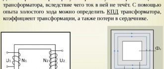
Transformer no-load mode
Idle circuit (XX) is the connection of a device when the rated alternating voltage is supplied to the primary winding, and the circuits of all secondary windings are open (no loads are connected).
In a voltage converter, the division of windings (coils) into primary and secondary is conditional. Any of them becomes primary when the original alternating voltage is applied to it. Others, in which EMF is induced, become, accordingly, secondary.
The idle test is carried out according to the scheme shown in the figure.
Consequently, any transformer, depending on the connection method, can be either a step-down or step-up transformer (except for an isolation transformer - with a transformation ratio equal to unity).
Since the secondary coil circuit is disconnected, there is no current in it (I2 = 0). I1 flows in the primary, forming the flux of the magnetic induction vector F1 in the magnetic circuit. The latter changes according to a sinusoidal law, but due to the magnetization reversal of the steel, it lags in phase from I1 by angle B (loss angle).
The following terminology applies:
- I1: transformer current XX;
- F1: working magnetic flux.
Under the influence of F1, an EMF arises in all coils:
- in primary – self-induction (E1);
- in secondary ones – mutual induction (E2).
The dependence of EMF on various parameters is determined by the formulas:
E1 = 4.44 * f * W1 * Ф1max *10 -8,
E2 = 4.44 * f * W2 * Ф1max * 10 -8, where
W1 and W2 - number of turns in the windings;
Ф1max is the magnitude of the magnetic flux at the maximum point.
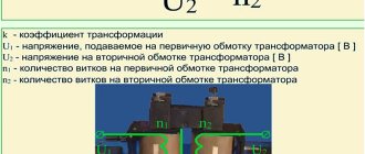
Consequently, the numerical value of the EMF is directly dependent on the number of turns of the coil. From the ratio of the EMF in the primary and secondary windings, the main parameter of the device is determined - the transformation ratio (K): K = E1 / E2 = W1 / W2.
Compared to the primary coil, the secondary coil contains:
- in a step-up transformer – more (K is less than one);
- in the downward direction it is less (K is greater than one).
In addition to the working (main) magnetic flux Fr1 is formed in the installation. These are power lines that branch off from the working magnetic flux F1 in the core and close through the air around the turns of the coils. Like F1, Fr1 is variable, which means that, according to the law of electromagnetic induction, it induces self-inductive emf Ep1 in the primary winding.
E1 and Ep1 are always directed opposite the voltage U1 applied to the primary winding. By the nature of their effect on current, they are similar to a resistor, which is why they are designated by the term “inductive reactance” (X).
Capacitive and inductive reactance
Consequently, creating I1, the voltage U1 overcomes the active resistance R1 of the primary coil and both self-induction emfs. Mathematically it looks like this: U1 = I1 * R1 + (-E1) + (-Ep1).
The recording is made in vector form, therefore, the symbols “-” are placed before the designations of the self-induction EMF: they indicate the opposite direction of these vectors relative to the voltage U1. The no-load current I1 is not strictly sinusoidal.
It is distorted because it contains the so-called third harmonic component (THC), caused by eddy currents, hysteresis and magnetic saturation of the magnetic circuit. But with a certain degree of approximation, suitable for practical calculations, it can be replaced by an equivalent sinusoidal current with an equivalent effective value.
How to calculate power losses in stacked cores?
The specific losses of magnetic material in stacked cores exceed those of pressed cores. The reason for the increase in losses is the negative impact of technological operations during the manufacture of cores. To take into account this influence, a loss increase factor kp is introduced:
where Рсн – specific power losses in a stacked (tape or laminated) core,
РV/ – specific losses of the material from which the core plates or strips are made,
kp – loss increase factor.
The values of this coefficient depend on the manufacturing technology, type of material, operating frequency and type of core. So for stacked cores (LS and ShS) made of electrical steel, it is determined by the following expression
And for split strip cores made of iron-nickel alloys
where ψа is a parameter taking into account the type of core. For detachable cores (ST, BT) ψа = 3, and for closed ones (TT) it is ψа = 1.
The table below shows typical values of the loss magnification factor
| Core type | Material | kp values at frequency in Hz | ||||
| View | Thickness | 50 | 400 | 2000 | 10000 | |
| AL and closed LS | Steels and alloys | 0,15-0,35 | 1,15 | 1,2 | 1,25 | 1,3 |
| 0,05 | — | 1,25 | 1,35 | 1,4 | ||
| Split drugs | Email those. become | 0,15-0,35 | 1,3 | 1,4 | 1,5 | 1,6 |
| 0,05 | — | 1,5 | 1,6 | 1,7 | ||
| 50N, 33NKMS | 0,05-0,1 | — | 1,7 | 1,8 | 1,9 | |
| 80НХС, 79НМ | 0,05-0,1 | — | 2,5 | 2,8 | 3 | |
The values of the additional loss coefficient kp are given for medium-sized cores (several tens of W). For smaller cores, the value of this coefficient must be increased by 1.2 - 1.3 times, and for large cores reduced by 1.2 - 1.3 times.
How to calculate power losses in transformer windings?
Power losses in the transformer windings ∆рк directly depend on their active resistance Ri. In addition, it is necessary to take into account the increase in resistance due to additional factors (increase in temperature and skin effect). In general, power losses in the windings are determined by the following expression
where N is the number of secondary windings,
рki – losses in the i-th winding,
Ii – current strength in the i-th winding,
Ri is the resistance of the i-th winding.
The winding resistance is calculated using a well-known formula, through resistivity
where lw is the average length of the winding turn, cm,
w – number of winding turns,
q – conductor cross-section, mm2,
ρ – resistivity of the conductor material, Ohm*mm2/m.
This expression is quite inconvenient to use in practice. Most often, the dimensions of the core are known, as well as its main parameters (areas and volumes). Therefore, you can use the following expression for power losses in the transformer windings
where koki is the window fill factor for the i-th winding,
Vki – geometric volume occupied by the i-th winding, cm3,
ji – current density for the i-th winding, a/mm2,
Soki – cross-sectional area of the i-th winding, mm2,
If the parameters ρ, j, kok are the same for all windings or their average values are taken, then we obtain the following expression
where Vk is the geometric volume occupied by the entire coil, cm3.
As already mentioned, the transformer heats up during operation. At the same time, the active resistance of the windings changes. The resistivity of a conductor with increasing temperature can be calculated using the following expressions
where kτ is a coefficient taking into account the increase in resistance due to rising temperature,
ρ20 – conductor resistivity at a temperature of 20°C,
αρ – temperature coefficient of resistance, for copper and aluminum αρ = 0.004 1/°С,
tp – operating temperature of the transformer, °C.
Since in most cases reference books indicate the resistivity of materials at a temperature of 20°C, the expression can be simplified
where τ is the transformer overheating.
The effect of temperature on the resistance of a transformer winding must always be taken into account when calculating the voltage drop across them.
Measurement procedure and scheme
Before carrying out the experiment, the process of demagnetization of the magnetic circuit of the transformer under test is carried out. This is done using a direct current passed through one of the low voltage side windings. The current connection is made repeatedly, each subsequent connection occurs with a change in polarity and a decrease in value.
The initial value should not be less than twice the expected no-load current. With each subsequent switching on, the value decreases by 30-40%. The process ends at a current less than the no-load current.
Vasiliev Dmitry Petrovich
Professor of Electrical Engineering, St. Petersburg State Polytechnic University
Ask a Question
To conduct the direct no-load test, the rated voltage is applied to the secondary winding of the transformer, with a deviation from the norm of ±5%. The neutral terminal, if present, is not used. The voltage in this case is strictly sinusoidal, with the nominal frequency of the network.
To carry out measurements, you will need three laboratory instruments with an accuracy class of at least 0.5. These are ammeters, voltmeters and wattmeters. ammeters are connected to each phase in series. voltmeters are switched on to the linear voltage of all three phases. The current windings of wattmeters are connected in series with ammeters.
The voltage windings of the wattmeters are connected according to the diagrams given. Voltage is applied and readings are taken from the instruments.
Abrahamyan Evgeniy Pavlovich
Associate Professor, Department of Electrical Engineering, St. Petersburg State Polytechnic University
Ask a Question
Strictly speaking, the measurement is carried out according to the same schemes that were used at the manufacturer to conduct the experiment. After all, the data obtained will need to be compared with the factory data. But, if a three-phase voltage source is not available, three measurements can be made by applying voltage to two phases of the transformer winding, short-circuiting the third, which remains free.
In this case, only linear voltage is used, since distortion of the curve shape due to nonlinear loads in the network has minimal influence on it. Using the same schemes, an idle test is carried out at a reduced (low) voltage.