Reactive power in the power system
Lecture No. 15
Reactive power in the power system. Reactive consumers
Power. Reactive power generation by ES generators
Plan.
1. General Provisions.
2. Regulating effect of load.
3. Reactive power consumers.
4. Generation of reactive power by ES generators.
From the balance of reactive power in the power system it follows that in the case when the generation of reactive power exceeds its consumption, the voltage in the network increases. When there is a shortage of reactive power, the voltage decreases. We already received this conclusion when we examined the vector diagram of a 110 kV power transmission line. The capacitive current of the no-load power line, or in other words, the power generated by the power line, increases the voltage at the end of the power line.
Unlike the active power balance, the reactive power balance cannot fully determine the requirements for reactive power sources. If active power is generated only by power plant generators, then reactive power can be obtained from additional sources that can be installed near consumers. These additional sources are called compensating installations.
When designing an electrical network, it is necessary to check the reactive power balance both throughout the power system as a whole and in its individual parts. In this case, the need for a reactive power reserve should also be taken into account.
The reactive power balance should be provided separately for each network mode. The characteristic modes in the system are:
· mode of the highest reactive load. The mode is characterized by the highest reactive power consumption and the highest power of compensating devices;
· mode of the highest active load. The mode is associated with the highest load of active power generators with the lowest generation of reactive power;
· mode of the least active load. In this mode, some generators are turned off. The production of reactive power by generators of power plants is reduced;
· post-emergency and repair modes. In these modes there are the greatest restrictions on the transfer of reactive power.
If there is a shortage of active power in the power system, it is covered by excess active power in other systems. To cover the lack of reactive power, it is more economical to generate it by compensating devices that are installed in a given power system, rather than transmitting it from neighboring systems.
Regulatory effect of load
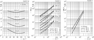
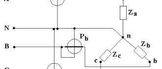
The change in active and reactive voltage occurs according to static characteristics (Fig. 16.1). Let's consider how the load reacts to a change in mode in the simplest system (Fig. 16.2).
During normal operation, the load buses are maintained at rated voltage. The consumer takes power from the network equal to P
2 +
j Q
2.
With a constant voltage at the beginning of the power line, the voltage at its end can be calculated as follows:
Let's assume that the voltage at the end of the power line decreases. In accordance with the static characteristics, the active and reactive power of the consumer will decrease.
Consequently, the power at the end of the transmission line and voltage loss will decrease, and the voltage at the end of the transmission line will increase.
This conclusion is valid when the voltage at the end of the power line is greater than the critical voltage:
.
The critical voltage is (0.7 – 0.8) from U
nom.
Thus, at voltages greater than critical, the load, changing its power, strives to maintain constant the voltage on its buses. In this case, they talk about the positive regulatory effect of the load.
At voltages less than critical, a negative regulating effect of the load appears. The active power of the consumer decreases in accordance with the static characteristics. Reactive power consumption begins to increase. Moreover, the value of reactive power increases to a greater extent than the decrease in active power. Consequently, the active power at the end of the transmission line decreases, the reactive power increases. The voltage loss in the area increases, and the voltage on the load busbars decreases. This leads to an increase in reactive power consumption and a further decrease in voltage, etc. A phenomenon occurs that is called a voltage avalanche. In such an accident, asynchronous motors are braked. The reactive power of asynchronous motors increases, the balance of reactive power is disrupted, and the consumption of reactive power significantly exceeds the generation:
.
This in turn leads to a decrease in voltage. The reduction in voltage during this accident can be stopped only by disconnecting the load.
To ensure that the voltage does not drop below critical, automatic excitation regulators (AEC) are installed on generators and powerful synchronous motors. Under their influence, generators and synchronous motors increase the production of reactive power.
Reactive power consumers
The work of capacitive consumers is based on the creation of an electric field, the energy of which is given to the source in the odd quarter (first, third) of the period, and in the even quarter (second, fourth) of the period is taken from the source. For inductive consumers, the work is based on the creation of a magnetic field. In this case, in the odd quarter (first, third) of the period, energy is taken from the source, and in the even quarter (second, fourth) of the period, it is given to the source.
Energy fluctuations in the magnetic and electric fields of various alternating current devices determine their consumption of reactive inductive or reactive capacitive power. In engineering practice under reactive power
refers to
inductive
power, which is consumed by the inductive elements of an electrical system and generated in the capacitive elements.
The main consumers of reactive power in electrical systems are transformers, overhead power lines, asynchronous motors, valve converters, induction electric furnaces, and welding units.
At industrial enterprises, the main consumers of reactive power are asynchronous motors. They account for 65-70% of the reactive power consumed by the enterprise. 20-25% of reactive power consumption falls on enterprise transformers and about 10% on other receivers and power lines.
The total reactive power losses in the network are about 50% of the power supplied to the network. This is much more than active power losses. For comparison, the average active power loss in power lines is 3%, and in transformers – 2%. Approximately 70-75% of all reactive power losses are losses in transformers. For example, in a three-winding transformer with a power of 40 MVA and a voltage of 220 kV (TDTN-40000/220) with a load factor of 0.8, reactive power losses amount to about 12% of the rated power of the transformer.
The total reactive power losses in the system consist of losses in the resistance and conductivity of power lines and losses in transformers:
.
Reactive power losses in power line resistances are calculated using the formula
and constitute approximately 5% of the power passing through power lines.
The generation of reactive power in transmission lines is defined as follows:
The average value of reactive power generated in a transmission line 100 km long is:
| U nom, kV | 110 | 150 | 220 |
| ΔQ s, Mvar | 3 | 6,5 | 12,6 |
For overhead power lines with a voltage of 110 - 150 kV, the reactive losses in resistance and generation in conductivity are approximately the same:
In this case, natural power is transmitted along the power lines.
Reactive power losses in transformer resistances are calculated using the formula:
and constitute approximately 10% of the transmitted power.
Generation of reactive power by ES generators
The total power generated by the generator includes active and reactive components:
.
The apparent power module can be found through the active power and power factor of the generator:
.
A change in reactive power occurs when the excitation current changes. In rated mode at rated power factor, the generator produces rated values of active P
rated and reactive
Q
rated powers. The generator can increase reactive power production above the rated power, but at a decrease in active power production relative to the rated power. Such an increase is allowed within limits that are limited by the rated values of the stator and rotor currents.
The conditions for limiting the generation of reactive power can be determined by their vector diagram. The generator equivalent circuit for constructing a vector diagram is shown in Fig. 16.3. The generator includes a synchronous inductive reactance xd
and EMF
E q
.
The magnitude of the complex emf is equal to the sum of the vectors U
g and voltage drop in resistance
xd
:
Eq _
=
U
g +
j
.
Let's build a VD (Fig. 16.4).
On the real axis we plot the voltage U
d. We get point
a
.
At an angle φ
nom we plot the current
I
nom.
We decompose it into active I
nom and reactive
I
nom components.
From point a
we plot the vector of the voltage drop in the resistance
xd
from the reactive component of the rated current.
It coincides in direction with the voltage U
g. We get the point
c
.
From point c
we plot the vector of the voltage drop in the resistance
xd
from the active component of the rated current.
This vector is perpendicular to the voltage U
g. We obtain point
b
.
Vector is the vector of the total voltage drop from the rated current in the resistance xd
:.
We connect the origin of coordinates with point b
.
The vector is proportional to the emf E q
and the excitation current.
From the origin with a radius equal to Eq
let's draw an arc.
It determines the permissible values of the excitation current or EMF Eq
according to the heating conditions of the generator rotor.
From point a
we draw an arc with a radius. It determines the permissible parameters of the generator based on the stator heating conditions.
Sides of triangle abc
are proportional to the following quantities:
.
Let's consider the operation of the generator at angle , that is, at (at a reduced cosine). The construction of a vector diagram is carried out in a similar way. We get a triangle. The mode allowed for the generator corresponds to the EMF value Eq1
. In this case we have:
(segment ac
1>
ac
);
(segment a b
1<
a b
).
Thus, the generator can produce reactive power greater than the rated power
but with a decrease in active power relative to the rated
The generator, when operating with increased cosine ( and ), produces active power greater than the rated power. In this case, the reactive power becomes less than the rated power:
P
2 >
P
nom and
Q
2 <
Q
nom.
EMF value Eq2
limited by stator heating.
Operating a generator at greater than rated active power is associated with turbine overload and is not always acceptable.
The possibility of increasing reactive power by reducing active power can be used in case of excess active power, that is, in minimum load mode. In this case, some generators may be switched to operate with a reduced power factor.
Reactive power reserve and the possibility of reactive power overloads are important during an emergency voltage drop. All generators have ATS devices, which, when the voltage at the generator terminals decreases, automatically increases the excitation current and reactive power generation.
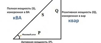
Electrical system mode parameters
The operating mode of the electrical system is characterized by the values of indicators of its condition, called mode parameters. All processes in electrical systems can be characterized by three parameters: voltage, current and active power. But for the convenience of mode calculations, other parameters are also used, in particular, reactive and apparent power. The product of the voltmeter and ammeter readings in an alternating current circuit is called apparent power. For a three-phase circuit, it is expressed by the formula: (1) where I is the current in one phase; U is linear voltage. The active power of three-phase alternating current is determined by the formula: (2) The cosφ multiplier is called the power factor. Angle φ indicates the phase shift of current and voltage. Based on these expressions, the total power S is represented by the hypotenuse of a right triangle, one leg of which represents the active power P = S cosφ, and the other the reactive power Q = S sinφ. Reactive power is also found from the expression: (3) where tgφ is the reactive power factor. It is worth remembering the conventions of interpreting Q as power. Only active power and energy can do work and be converted into mechanical, thermal, light and chemical energy. Active power is due to the conversion of prime mover energy obtained from a natural source into electricity. Reactive power is not converted into other types of power, does not do work, and therefore is called power conventionally. Reactive power is used to create magnetic and electric fields. For analyzing modes in sinusoidal current circuits, reactive power is a very convenient characteristic, widely used in practice. A feature of the production and consumption of electricity is the equality of electricity (power) generated and consumed per unit of time. Consequently, in the electrical system the equality (balance) for active powers must be satisfied: (4) where Pr is the total active power supplied to the network by generators of power plants included in the system; RPOtr - total combined active load of system consumers; ARper - total losses of active power in all elements of electricity transmission (lines, transformers) through electrical networks; Рсн is the total active load of auxiliary needs of all power plants of the system at the highest consumer load. The main share of generated power goes to cover the load of consumers. The total transmission losses depend on the length of the electrical network lines, their cross-sections and the number of transformations and are within 5...15% of the total load. The auxiliary load of power plants depends on their type, type of fuel and type of equipment; it is for thermal power plants
- .12%, for hydropower plants - 0.5... 1% of the power plant capacity.
Equality (4) allows us to determine the operating active power of the system. The available power of the generators Pr.disp of the system is slightly greater than the operating power in the maximum load mode Pr.max; it is necessary to take into account the need for redundancy during emergency and planned (repair) outages of part of the main equipment of the electric power system: (5) where Pr res is the reserve power of the system, which must be at least 10% of its operating power. If the balance of active powers is disturbed, for example, if (6) the frequency in the system decreases.
The main consumers of reactive power at industrial enterprises
Let's consider the main types of electrical receivers for various technological purposes, electrical consumers of different industries, the nature of their loads and the features of operating modes. Electric motors are used in drives of various production mechanisms at all industrial enterprises. An electric drive is a complex of electrical machines, devices and control systems in which electric motors are structurally connected to the actuator and convert electrical energy into mechanical work. In installations that do not require speed control during operation, only AC electric drives (asynchronous and synchronous motors) are used. current is the main type of electrical receivers in industry, accounting for about 2/3 of the total power. The share of electricity consumption by asynchronous motors with a voltage of 0.38 kV is 52% in mechanical engineering. Electric thermal power, electric welding, electrolysis and other consumers account for about 1/3 of the total industrial load. Electrothermal receivers, in accordance with heating methods, are divided into the following groups: electric arc furnaces for melting ferrous and non-ferrous metals, induction heating installations for melting and heat treatment of metals and alloys, electric resistance furnaces, electric welding installations, thermal household appliances. The most widespread in workshop electrical networks with a voltage of 0.38 kV are resistance furnaces and induction heating installations. Direct and indirect resistance furnaces have a power of up to 2000 kW and are connected to a network voltage of 0.38 kV, the power factor is close to 1.0. Industrial and high frequency induction melting furnaces represent a three-phase electrical load in a “quiet” operating mode. High-frequency furnaces are powered by valve frequency converters, to which an alternating current of 0.4 kV is supplied. Induction furnaces have a low power factor: from 0.1 to 0.5. Electric welding installations of alternating current arc and contact welding represent a single-phase uneven and non-sinusoidal load with a low power factor: 0.3 for arc welding and 0.7 for contact welding. Electrochemical and electrolysis plants operate on direct current, which is obtained from converter substations that rectify three-phase alternating current. The power factor of the installations is 0.8...0.9. Electric lighting installations with incandescent, fluorescent, arc, mercury, sodium, and xenon lamps are used in all enterprises for indoor and outdoor lighting. In production shops, currently, mainly high-pressure mercury arc lamps of the DRL and DRI 220 V types are used. Emergency lighting, accounting for 10% of the total, is carried out with incandescent lamps. Only incandescent lamps have a power factor of 1.0.
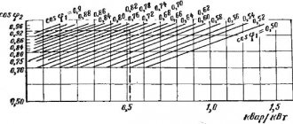
Power regulation of compensating devices
The setting by the supply power system of two values of input reactive power, which can be transferred to the enterprise in the modes of the highest and lowest active loads of the system, Qs1 and Oe2, respectively (with Oe2 = 0 in almost all cases), predetermines the need to regulate the consumption of reactive power by the enterprise during the day. To regulate reactive power consumption, automatic control of the excitation of synchronous machines and control of capacitor banks are used. Regulation of reactive power by capacitors can only be carried out in steps by dividing the batteries into parts. The greater the number of such stages, the more perfect the regulation, but the greater the cost of installing switches and protective equipment. Typically, the power of capacitor banks is divided into two stages:
- basic QK 6az, equal to the reactive load of the enterprise during the hours of minimum active loads of the power system, switched on constantly;
- adjustable QK per = QKy - QK 6az, included in the hours of maximum active loads of the power system.
Step control of capacitor banks can be done either manually or automatically. Automatic regulation of capacitor banks can be carried out in the function:
- tension;
- load current;
- direction of reactive power relative to the direction of active power;
- by time of day.
Rice. 5. Diagram of the influence of the installation of compensating devices on the parameters of the electrical network modes
Therefore, at voltages up to 1 kV, contactors are usually used to switch BCs; at voltages above 1 kV, air, SF6 or vacuum circuit breakers are used. To eliminate transient processes when switching BC, instead of switches, you can use thyristor switches, which allow you to turn on capacitors at the moment when the instantaneous voltage on the capacitors is equal to the network voltage, and turn them off when the instantaneous value of the current in the capacitors is zero.
The installation of compensating devices affects the parameters of the electrical network modes, changing the currents in the branches and voltages in the nodes. Let's consider the effect of reactive power compensation using the example of one branch of the circuit (Fig. 5). Reduction of total powers and currents. If there is a KU at the end of the branch with power QK, the total power flowing in the branch at rated voltage UH0M: (27) where tgφ is the load reactive power factor; Cq is the degree of reactive power compensation, equal to the ratio of the reactive power of the heater at the rated voltage to the reactive load of the electric consumer EP Qn nom at the rated voltage: (28) Since the cross-sectional areas of the lines and the power of the transformers are selected according to the total power (or current), its reduction at Cq < 1 allows in some cases the use of equipment of lower ratings, i.e. reduce capital costs; if the network is already in operation, then reactive power compensation allows you to increase its active power capacity and, therefore, do not change electrical equipment when the consumer load increases. With full compensation of the reactive load, i.e. when Cq = 1, the power of the branch has a minimum value: when Cq > Qn nom, the total power becomes greater than the minimum Sc = 1. Reduced load power losses. For each branch with active R and reactive X resistance, the total power loss is defined as: (30) Total power loss in the network when only the active power of the consumer flows at the rated voltage UH0M, i.e. minimum possible active power losses, all other things being equal: (31) Relation (32) allows you to analyze the influence of the degree of reactive power compensation Cq at different values of the load reactive power factor tgφ on load power losses. Note that d0 = I2 if the voltage is equal to the nominal value UH0M. In Fig. Figure 6 shows the dependences I2 = AS/ASp for different values of the reactive power factor tgφ = 0.4; 1; 1.5 and rated voltage U nom, from which we can draw a conclusion about the effectiveness of the degree of reactive power compensation. As can be seen from these dependencies, the level of the I2 ratio is primarily determined by the degree of reactive power compensation and the reactive power factor. For example, without compensation at Cq = 0 and tanφ = 1: I2 = 2, i.e. real power losses are twice as large as the minimum; and with full compensation, Cq = 1 and any value of the reactive power factor I2 = 1. Note that with overcompensation, Cq > 1 and the load power losses become greater than the minimum ASp. Reduced voltage losses. Voltage loss at rated voltage at the consumer: where £ is the ratio of the reactive and active resistance of the network element: e = X/R. It is obvious that reactive power compensation has the greatest impact on voltage losses in elements with a large value of e, i.e. in elements with a predominance of reactance, such as transformers and overhead lines.
Rice. 6. Dependencies I2 = AS/ASp = fCq; tg
The voltage at the receiving end of the line UK is equal to the difference between the start voltage Un and the voltage loss AUnK, i.e.: (34) Consequently, when installing the KU, the voltage at the end of the line increases. With overcompensation (Cq > 1), voltage losses can take on a negative value AUnK < O, the voltage at the end of the line can become greater than the voltage at the beginning, i.e. U > U .